How to find out the pump flow rate
The calculation formula looks like this: Q = 0.86R / TF-TR
Q - pump flow rate in cubic meters / h;
R is the thermal power in kW;
TF is the temperature of the coolant in degrees Celsius at the inlet to the system,
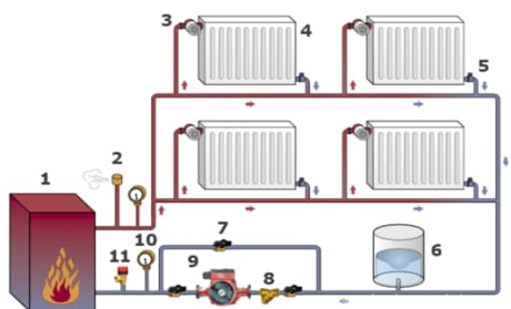
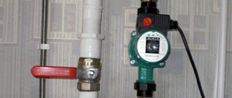
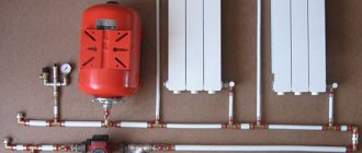
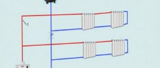
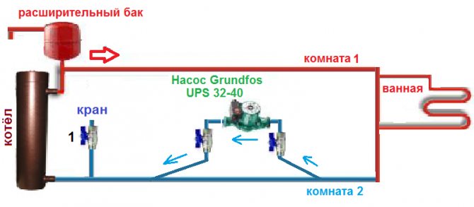
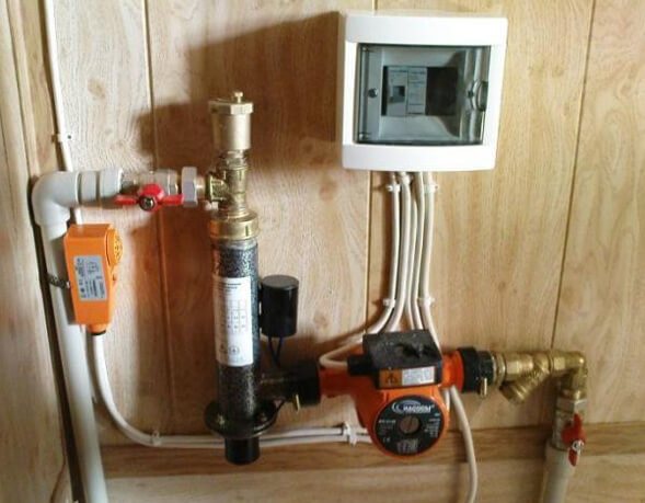
Layout of the heating circulation pump in the system
Three options for calculating thermal power
Difficulties may arise with the determination of the thermal power indicator (R), therefore it is better to focus on generally accepted standards.
Option 1. In European countries, it is customary to take into account the following indicators:
- 100 W / sq. - for private houses of small area;
- 70 W / sq. M. - for high-rise buildings;
- 30-50 W / sq. - for industrial and well-insulated living quarters.
Option 2. European standards are well suited for regions with mild climates. However, in the northern regions, where there are severe frosts, it is better to focus on the norms of SNiP 2.04.07-86 "Heating networks", which take into account the outside temperature up to -30 degrees Celsius:
- 173-177 W / m2 - for small buildings, the number of storeys of which does not exceed two;
- 97-101 W / m2 - for houses from 3-4 floors.
Option 3. Below is a table by which you can independently determine the required heat output, taking into account the purpose, degree of wear and tear and thermal insulation of the building.
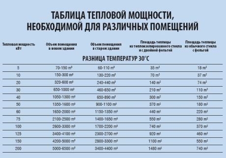
Table: how to determine the required heat output
Formula and tables for calculating hydraulic resistance
Viscous friction occurs in pipes, valves and any other nodes of the heating system, which leads to losses in specific energy. This property of systems is called hydraulic resistance. Distinguish between friction along the length (in pipes) and local hydraulic losses associated with the presence of valves, turns, areas where the diameter of the pipes changes, etc. The hydraulic resistance index is designated by the Latin letter "H" and is measured in Pa (pascals).
Calculation formula: H = 1.3 * (R1L1 + R2L2 + Z1 + Z2 +…. + ZN) / 10000
R1, R2 denote the pressure loss (1 - at the supply, 2 - at the return) in Pa / m;
L1, L2 - length of the pipeline (1 - supply, 2 - return) in m;
Z1, Z2, ZN - hydraulic resistance of system units in Pa.
To make it easier to calculate the pressure loss (R), you can use a special table, which takes into account the possible pipe diameters and provides additional information.
Pressure drop table
Average data for system elements
The hydraulic resistance of each element of the heating system is given in the technical documentation. Ideally, you should use the characteristics specified by the manufacturers. In the absence of product passports, you can focus on the approximate data:
- boilers - 1-5 kPa;
- radiators - 0.5 kPa;
- valves - 5-10 kPa;
- mixers - 2-4 kPa;
- heat meters - 15-20 kPa;
- check valves - 5-10 kPa;
- control valves - 10-20 kPa.
The flow resistance of pipes made of various materials can be calculated from the table below.
Pipe pressure loss table
Basic principles of pump selection. Calculation of pumps
All the variety of pump types can be divided into two main groups, the calculation of the performance of which has fundamental differences. According to the principle of operation, pumps are divided into dynamic and positive displacement pumps. In the first case, the pumping of the medium occurs due to the action of dynamic forces on it, and in the second case, due to a change in the volume of the working chamber of the pump.
Dynamic pumps include:
1) Friction pumps (vortex, screw, disk, jet, etc.) 2) Vane (axial, centrifugal) 3) Electromagnetic
Positive displacement pumps include: 1) Reciprocating (piston and plunger, diaphragm) 2) Rotary 3) Vane
Below you will find formulas for calculating performance for the most common types.
| More information about piston pumps: Piston pumps Plunger pumps |
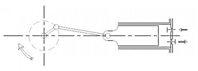
Piston pumps (positive displacement pumps)
The main working element of a piston pump is the cylinder in which the piston moves. The piston performs reciprocating movements due to the crank mechanism, which ensures a consistent change in the volume of the working chamber. In one full revolution of the crank from the extreme position, the piston makes a full forward stroke (discharge) and backward (suction). During pumping, an excess pressure is created in the cylinder by the piston, under the action of which the suction valve closes, and the discharge valve opens, and the pumped liquid is supplied to the discharge pipeline. During suction, a reverse process occurs, in which a vacuum is created in the cylinder due to the movement of the piston backward, the discharge valve closes, preventing the backflow of the pumped medium, and the suction valve opens and the cylinder is filled through it. The actual performance of reciprocating pumps is somewhat different from the theoretical, which is associated with a number of factors, such as liquid leaks, degassing of gases dissolved in the pumped liquid, delayed opening and closing of valves, etc.
For a single-acting piston pump, the flow rate formula will look like this:
Q = F S n ηV
Q - flow rate (m3 / s) F - piston cross-sectional area, m2 S - piston stroke length, m n - shaft rotation frequency, sec-1 ηV - volumetric efficiency
For a double-acting piston pump, the formula for calculating the capacity will be slightly different, due to the presence of a piston rod, which reduces the volume of one of the working chambers of the cylinder.
Q = F S n + (F-f) S n = (2F-f) S n
Q - flow rate, m3 / s F - piston cross-sectional area, m2 f - rod cross-sectional area, m2 S - piston stroke length, m n - shaft speed, sec-1 ηV - volumetric efficiency
If we neglect the volume of the rod, then the general formula for the performance of a piston pump will look like this:
Q = N F S n ηV
Where N is the number of actions performed by the pump during one revolution of the shaft.
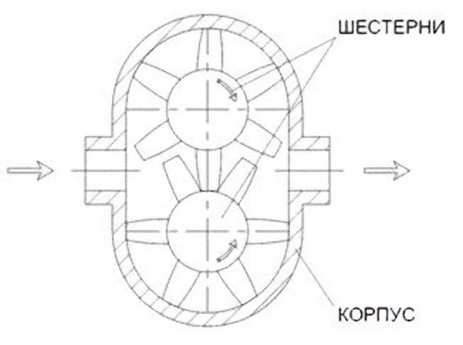
Gear pumps (positive displacement pumps)
| More information on gear pumps: Gear pumps |
In the case of gear pumps, the role of the working chamber is played by the space limited by two adjacent gear teeth. Two gears with external or internal gearing are housed in the housing. The suction of the pumped medium into the pump occurs due to the vacuum created between the gear teeth that are disengaged. Fluid is carried by the teeth in the pump casing and then squeezed out into the discharge nozzle as the teeth re-engage. For the flow of the pumped medium in gear pumps, end and radial clearances between the housing and the gears are provided.
The capacity of a gear pump can be calculated as follows:
Q = 2 f z n b ηV
Q - gear pump capacity, m3 / s f - cross-sectional area of the space between adjacent gear teeth, m2 z - number of gear teeth b - gear tooth length, m n - tooth rotation frequency, sec-1 ηV - volumetric efficiency
There is also an alternative formula for calculating the performance of a gear pump:
Q = 2 π DH m b n ηV
Q - gear pump capacity, m3 / s DН - gear initial diameter, m m - gear modulus, m b - gear width, m n - gear rotation frequency, sec-1 ηV - volumetric efficiency
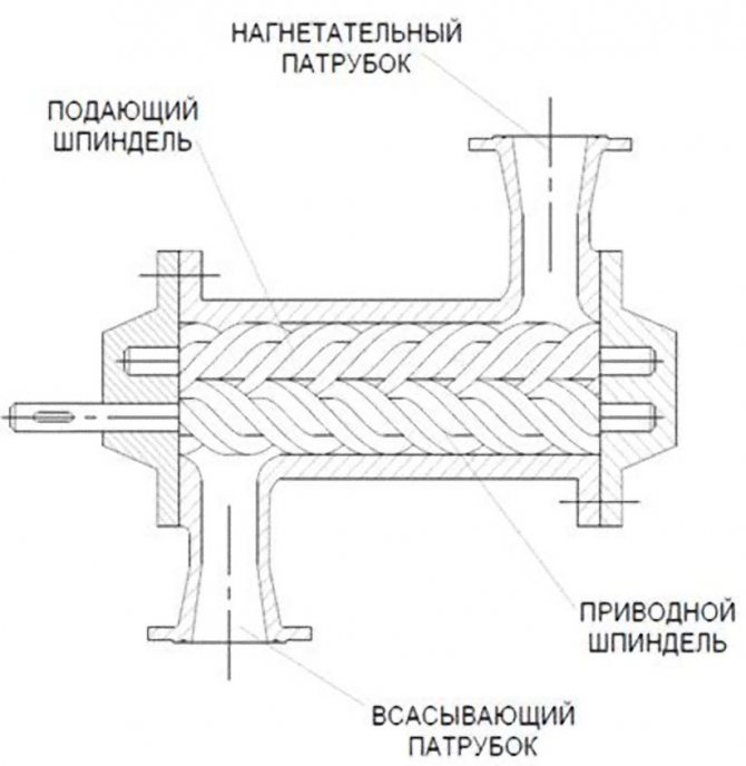
Screw pumps (positive displacement pumps)
In pumps of this type, the pumping of the medium is ensured by the operation of a screw (single-screw pump) or several meshed screws, if we are talking about multi-screw pumps. The profile of the screws is selected in such a way that the pump discharge area is isolated from the suction area. The screws are located in the housing in such a way that, during their operation, areas of the enclosed space filled with the pumped medium are formed, bounded by the profile of the screws and the housing and moving in the direction of the discharge area.
The performance of a single-screw pump can be calculated as follows:
Q = 4 e D T n ηV
Q - screw pump capacity, m3 / s e - eccentricity, m D - rotor screw diameter, m T - stator helical surface pitch, m n - rotor speed, sec-1 ηV - volumetric efficiency
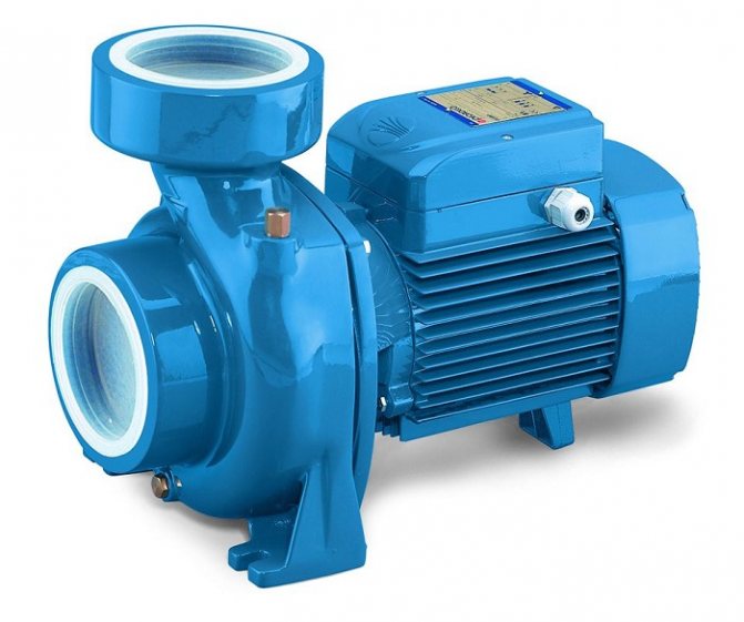
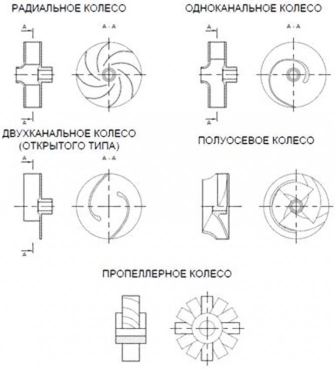
Centrifugal pumps
| More information on centrifugal pumps: Centrifugal pumps |
Centrifugal pumps are one of the most numerous examples of dynamic pumps and are widely used. The working body in centrifugal pumps is a wheel mounted on a shaft, which has blades enclosed between the discs and located inside the volute casing.
Due to the rotation of the wheel, a centrifugal force is generated that acts on the mass of the pumped medium inside the wheel, and transfers it part of the kinetic energy, which then turns into potential energy of the head. The vacuum created at the same time in the wheel ensures a continuous supply of the pumped medium from the suction branch pipe. It is important to note that before starting operation, the centrifugal pump must be pre-filled with the pumped medium, since otherwise the suction force will not be enough for the normal operation of the pump.
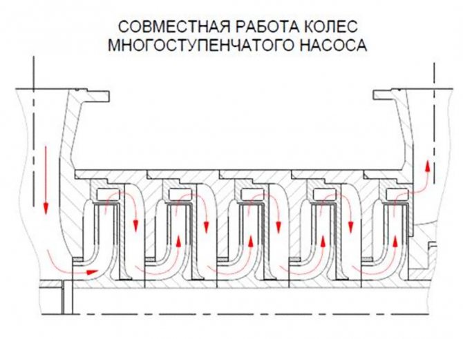
A centrifugal pump can have more than one working body, but several. In this case, the pump is called multistage. Structurally, it differs in that several impellers are located on its shaft at once, and the liquid passes sequentially through each of them. A multistage pump with the same performance will create a higher head in comparison with a similar single-stage pump.
The performance of a centrifugal pump can be calculated as follows:
Q = b1 (π D1-δ Z) c1 = b2 (π D2-δ Z) c2
Q - centrifugal pump capacity, m3 / s b1,2 - wheel passage widths at diameters D1 and D2, m D1,2 - outer diameter of the inlet (1) and outer diameter of the wheel (2), m δ - blade thickness, m Z - number of blades C1,2 - radial components of absolute velocities at the entrance to the wheel (1) and exit from it (2), m / s
Why do you need a circulation pump
It is no secret that most consumers of heat supply services living on the upper floors of high-rise buildings are familiar with the problem of cold batteries. It is caused by the lack of necessary pressure. Since, if there is no circulation pump, the coolant moves through the pipeline slowly and as a result cools down on the lower floors
That is why it is important to correctly calculate the circulation pump for heating systems.
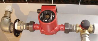
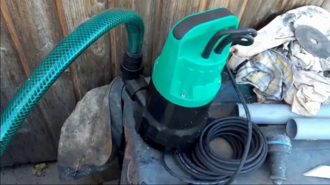
Owners of private households often face a similar situation - in the most remote part of the heating structure, the radiators are much colder than at the starting point. Experts consider the installation of a circulation pump as the best solution in this case, as it looks like in the photo. The fact is that in houses of small size, heating systems with natural circulation of coolants are quite effective, but even here it does not hurt to think about purchasing a pump, because if you correctly configure the operation of this device, heating costs will be reduced.
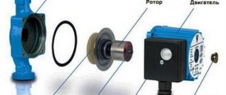
What is a circulation pump? This is a device consisting of a motor with a rotor immersed in a coolant.The principle of its operation is as follows: while rotating, the rotor forces the liquid heated to a certain temperature to move through the heating system at a given speed, as a result of which the required pressure is created.
The pumps can operate in different modes. If you make the installation of a circulation pump in the heating system for maximum work, a house that has cooled down in the absence of the owners can be warmed up very quickly. Then consumers, having restored the settings, receive the required amount of heat at minimal cost. Circulation devices are available with "dry" or "wet" rotor. In the first version, it is partially immersed in the liquid, and in the second - completely. They differ from each other in that pumps equipped with a "wet" rotor are less noisy during operation.
Calculation of a centrifugal pump
The calculation of a centrifugal pump consists in determining two parameters necessary for the operation of the system - supply and head. Depending on the installation scheme, the approach to calculating the specified parameters should be different.
Calculation of the booster pump
for the water supply system, it is performed according to the load of the hour of maximum water consumption, and the pressure is determined by the difference between the set pressure at the inlet to the water supply system and the pressure at the inlet of the water supply system.
The pressure at the inlet to the water supply system is equal to the sum of the excess pressure at the upper draw-off point, the height of the water column from the pump to the upper point and the head loss in the section from the booster pump to the upper point. Excessive pressure at the upper draw-off point is usually taken as 5-10 mWC.
Calculation of the make-up pump
for the heating system, they are performed based on the maximum permissible filling time of the system and its capacity. The heating system filling time is usually taken no more than 2 hours. The head of the make-up pump is determined by the difference between the pump cut-off pressure (system full) and the pressure at the connection of the make-up line.
Calculation of the circulation pump
for the heating system, they are performed based on the heat load and the calculated temperature schedule. The pump flow is proportional to the heat load and inversely proportional to the calculated temperature difference in the supply and return pipelines. The head of the circulation pump is determined only by the hydraulic resistance of the heating system, which must be indicated in the project.
Nominal head
The pressure is the difference between the specific energies of water at the outlet of the unit and at the inlet to it.
The pressure is:
- Volume;
- Mass;
- Weighted.
Before buying a pump, you should ask the seller everything about the warranty.
Weighted is important in conditions of a certain and constant gravitational field. It rises with a reduction in the acceleration of gravity, and when weightlessness is present, it equals infinity. Therefore, the weight pressure, which is actively used today, is uncomfortable for the characteristics of pumps for aircraft and space objects.
Full power will be used for starting. It is suitable externally as drive energy for an electric motor or with a flow rate of water, which is supplied to the jet device under special pressure.
Circulation pump speed control
Most models of the circulation pump have a function for adjusting the speed of the device. As a rule, these are three-speed devices that allow you to control the amount of heat that is sent to heat the room. In the event of a sharp cold snap, the speed of the device is increased, and when it becomes warmer, it is reduced, while the temperature regime in the rooms remains comfortable for staying in the house.
To change the speed, there is a special lever located on the pump housing. Models of circulation devices with an automatic control system of this parameter depending on the temperature outside the building are in great demand.
Selection of a circulation pump for a heating system criteria
When making the choice of a circulation pump for the heating system of a private house, they almost always give preference to models with a wet rotor, specially designed to work in any household mains of various lengths and supply volumes.
Compared to other types, these devices have the following advantages:
- low noise level,
- small overall dimensions,
- manual and automatic adjustment of the number of revolutions of the shaft per minute,
- pressure and volume indicators,
- suitable for all heating systems in individual houses.
Pump selection by number of speeds
To increase the efficiency of work and save energy resources, it is better to take models with a step (from 2 to 4 speeds) or automatic control of the speed of the electric motor.
If automation is used to control the frequency, then the energy savings in comparison with standard models reach 50%, which is about 8% of the electricity consumption of the whole house.
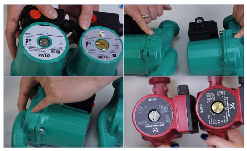
Fig. 8 Distinguishing a counterfeit (right) from the original (left)
What else to pay attention to
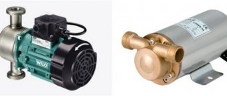
When buying popular Grundfos and Wilo models, there is a high probability of a fake, so you should know some of the differences between the originals and their Chinese counterparts. For example, German Wilo can be distinguished from a Chinese counterfeit by the following features:
- The original sample is slightly larger in overall dimensions; a serial number is stamped on its top cover.
- The embossed arrow of the direction of fluid movement in the original is placed on the inlet pipe.
- Air release valve for a fake yellow brass (the same color in counterparts under Grundfos)
- The Chinese counterpart has a bright shiny sticker on the back indicating the energy-saving classes.
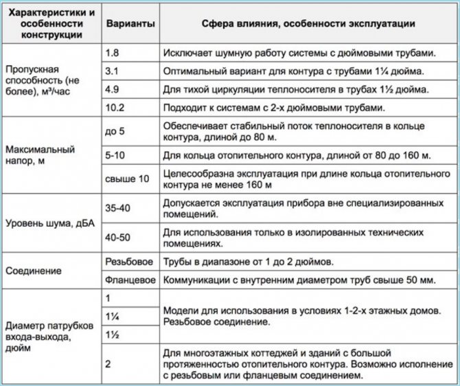
Fig. 9 Criteria for the selection of a circulation pump for heating
Selection of a centrifugal pump
To select a centrifugal pump, a graphical dependence of the pressure on the flow is used, which is individual for each model and is given in the manufacturers' catalogs.
The method of selecting a centrifugal pump depends on the tasks assigned to it. To select a booster pump, they are set by the flow rate and a perpendicular is drawn from the abscissa axis to the pump characteristic curve, the resulting operating point will determine the head at a given flow rate.
The circulation pump is selected by superimposing on the pump characteristic, the hydraulic characteristic of the circulation ring, which reflects the dependence of the head loss on the flowing flow. The duty point will be at the intersection of the pump and circulating ring characteristics.
If several models correspond to the specified parameters, choose a less powerful pump operating in a mode with higher efficiency. When choosing a centrifugal pump for a network with a variable water flow, it is better to give preference to a model with a flatter pressure characteristic and a wide flow range.
Noise performance often becomes the dominant parameter when selecting pumps for installation in residential buildings. In such cases, it is recommended to select a pump with a lower power electric motor and a rotational speed of no more than 1500 rpm.
How to choose and buy a circulation pump
The circulation pumps are faced with some specific tasks, different from water pumps, borehole pumps, drainage pumps, etc. If the latter are designed to move liquid with a specific outlet point, then circulating and recirculating pumps simply "drive" the liquid in a circle.
I would like to approach the selection somewhat non-trivially and offer several options. So to speak, from simple to complex - start with the recommendations of the manufacturers and, lastly, describe how to calculate the circulation pump for heating according to the formulas.
Choose a circulation pump
This simple way to select a circulation pump for heating was recommended by one of the WILO pump sales managers.
It is assumed that the heat loss of the room per 1 sq. M. will be 100 watts.Formula for calculating consumption:
Total heat loss at home (kW) x 0.044 = flow rate of the circulation pump (m3 / hour)
For example, if the area of a private house is 800 sq. M. the required flow rate will be equal to:
(800 x 100) / 1000 = 80 kW - heat loss at home
80 x 0.044 = 3.52 cubic meters / hour - the required flow rate of the circulation pump at a room temperature of 20 degrees. FROM.
From the WILO range, the TOP-RL 25 / 7,5, STAR-RS 25/7, STAR-RS 25/8 pumps are suitable for such requirements.
Regarding the pressure. If the system is designed in accordance with modern requirements (plastic pipes, closed heating system) and there are no non-standard solutions, such as high number of storeys or long heating pipelines, then the pressure of the above pumps should be enough "headlong".
Again, such a selection of a circulation pump is approximate, although in most cases it will satisfy the required parameters.
Choose a circulation pump according to the formulas.
If you want to deal with the required parameters and select it according to the formulas before buying a circulation pump, then the following information will come in handy.
determine the required pump head
H = (R x L x k) / 100, where
H - required pump head, m
L is the length of the pipeline between the most distant points "there" and "back". In other words, it is the length of the largest "ring" from the circulation pump in the heating system. (m)
An example of calculating a circulation pump using the formulas
There is a three-storey house with dimensions of 12m x 15m. Floor height 3 m. The house is heated by radiators (∆ T = 20 ° C) with thermostatic heads. Let's make a calculation:
required heat output
N (from.pl) = 0.1 (kW / sq. M.) X 12 (m) x 15 (m) x 3 floors = 54 kW
calculate the flow rate of the circulation pump
Q = (0.86 x 54) / 20 = 2.33 cubic meters / hour
calculate the pump head
The plastic pipe manufacturer TECE recommends the use of pipes with a diameter at which the fluid flow rate is 0.55-0.75 m / s, the resistivity of the pipe wall is 100-250 Pa / m. In our case, a 40mm (11/4 ″) pipe can be used for the heating system. At a flow rate of 2.319 cubic meters / hour, the flow rate of the coolant will be 0.75 m / s, the resistivity of one meter of the pipe wall is 181 Pa / m (0.02 m.wc).
WILO YONOS PICO 25 / 1-8
GRUNDFOS UPS 25-70
Almost all manufacturers, including such "giants" as WILO and GRUNDFOS, post on their websites special programs for the selection of a circulation pump. For the aforementioned companies, these are WILO SELECT and GRUNDFOS WebCam.
The programs are very convenient and easy to use.
Particular attention should be paid to the correct entry of values, which often causes difficulties for untrained users.
Buy circulation pump
When buying a circulation pump, special attention should be paid to the seller. Currently, there are a lot of counterfeit products on the Ukrainian market.
How can you explain that the retail price of a circulation pump on the market can be 3-4 times less than that of a representative of the manufacturer's company?
According to analysts, the circulation pump in the domestic sector is the leader in terms of energy consumption. In recent years, the companies have offered very interesting new products - energy-saving circulation pumps with automatic power control. From the household series, WILO has YONOS PICO, GRUNDFOS has ALFA2. Such pumps consume electricity by several orders of magnitude less and significantly save owners' money costs.
Determination of the required head in the building and selection of pumping equipment
⇐ back123456
The pressure in the building's water supply system must ensure uninterrupted water supply to all consumers. Therefore, its value is determined in the worst conditions (at the hour of maximum water consumption).
Required pressure in the building H m, m
water. article is determined by the formula:
Htr = Hgeom + hv + hcch + H + hj (10)
where: Hgoom is the geometric height of the elevator.
hv is the pressure loss at the inlet (before the water);
hc - loss of head in the water meter;
hj - minimum free head in front of the valve (in accordance with Appendix 2)
H - The total loss of the network, taking into account the local resistance, is determined by the formula:
(11)
where: Kl - coefficient taking into account local resistance and adopted: 0.3 - in the networks of household pipelines and drinking water for residential and public buildings; 0.2 - in the networks of general commercial and heating pipelines of residential and public buildings and in industrial water supply networks; 0.15 - in integrated networks of gas and gas pipelines.
The inlet loss hv is determined by performing the hydraulic calculation of the internal water supply system.
The head loss in the water meter is determined at the time of meter selection.
In the case of a fire protection system for water supply, if the selected meter size does not allow for the maximum consumption of the economic and fire flow, the leakage of current passing through the bypass line meter is prevented; in this case, the loss of the numerator is considered to be zero.
Geometric height of water rise Xgeom, taken as a mark of the difference between the insulating hole of plumbing fixtures and the floor area above the level of the attachment point of the internal water supply to the city network (above the point of connection to the city network)
Pumping units
Requirements for the location of the pumps and the choice of their installation scheme.
The required Htr pressure is compared with the Hgar guarantee. If HghárHHtr manages the internal water supply, this will be ensured by using the pressure in the external water supply network.
When Hghar ≤Htr, the head must be enlarged with pumps. The pump head is determined by the formula:
Hnas = Htr-Hgar (12)
If Htr-Hghar = 1 ... 1.5 m, you can increase the pipe diameter in individual sections with subsequent correction of the calculation of the required head.
Depending on the calculated maximum water flow rate at the inlet and at a certain pressure, the pump is selected from the catalog.
Positioning the device directly under residential apartments, children or rooms of a group of kindergartens and kindergartens, classrooms, schools, hospital wards, office premises of office buildings, classrooms of educational institutions and other similar premises is not allowed, therefore they should be placed on the premises of heating stations, boilers and boiler rooms.
Since there is no need to design the aforementioned room for operation in the course, if it is necessary to increase the pressure on the network, only the pump and its technical characteristics need to be selected.
links
first
Kalitsun V.I., Kedrov B.S., Laskov Yu.M. Hydraulics, water supply and waste water. M. Stroyizdat, 1980.
2. Cedars B.S., Lovtsov E.N. Plumbing equipment building. Moscow, Stroyizdat, 1989.
3. SNiP 2.04.01-85 Internal water supply and sewerage of buildings. Design standards.
fourth
Shevelev F.A., Shevelev A.A. Tables for hydraulic calculation of water pipes.
Checking the selected motor a. Checking the rudder shift duration
For the selected pump, look at the graphs of the dependence of the mechanical and volumetric efficiency on the pressure generated by the pump (see Fig. 3).
4.1. We find the moments arising on the shaft of the electric motor at different angles of the rudder shift:
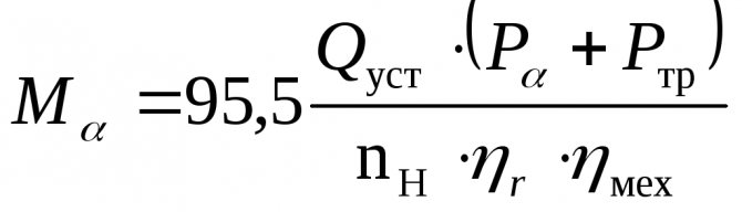
,
Where: M
α is the moment on the shaft of the electric motor (Nm);
Q
mouth - installed pump capacity;
P
α is the oil pressure generated by the pump (Pa);
P
tr - pressure loss due to oil friction in the pipeline (3.4 ÷ 4.0) · 105 Pa;
n
n - the number of revolutions of the pump (rpm);
η
r - hydraulic efficiency associated with fluid friction in the working cavities of the pump (for rotary pumps ≈ 1);
η
fur - mechanical efficiency, taking into account friction losses (in oil seals, bearings and other rubbing parts of pumps (see graph in Fig. 3).
We enter the calculation data in table 4.
4.2. We find the rotation speed of the electric motor for the obtained values of the moments (according to the constructed mechanical characteristic of the selected electric motor - see section 3.6). We enter the calculation data in table 5.
Table 5
| α ° | n, rpm | ηr | Qα, m3 / s |
| 5 | |||
| 10 | |||
| 15 | |||
| 20 | |||
| 25 | |||
| 30 | |||
| 35 |
4.3. We find the actual performance of the pump at the obtained speeds of the electric motor
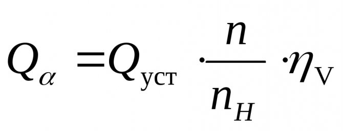
,
Where: Q
α is the actual capacity of the pump (m3 / sec);
Q
mouth - installed pump capacity (m3 / sec);
n
- actual speed of rotation of the pump rotor (rpm);
n
n - rated speed of rotation of the pump rotor;
η
v - volumetric efficiency, taking into account the return bypass of the pumped liquid (see graph 4.)
We enter the calculation data in table 5. Build a graph Q
α
=f(α)
- see fig. four
.
Fig. 4. Schedule Q
α
=f(α)
4.4. We divide the resulting schedule into 4 zones and determine the operating time of the electric drive in each of them. The calculation is summarized in table 6.
Table 6
| Zone | Boundary angles of zones α ° | Hi (m) | Vi (m3) | Qav.z (m3 / sec) | ti (sec) |
| I | |||||
| II | |||||
| III | |||||
| IV |
4.4.1. Finding the distance traveled by the rolling pins within the zone
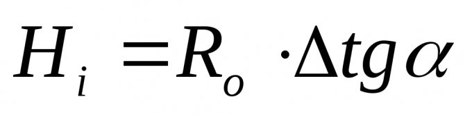
,
Where: Hi
- the distance traveled by the rolling pins within the zone (m);
Ro
- distance between the axes of the stock and rolling pins (m).
4.4.2. Find the volume of oil pumped within the zone
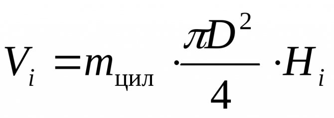
,
Where: Vi
- the volume of the pumped-over oil within the zone (m3);
m
cyl - the number of pairs of cylinders;
D
- diameter of the plunger (rolling pin), m
4.4.3. Find the duration of the rudder shift within the zone
,
Where: ti
- the average duration of the rudder shift within the zone (sec);
Q
Wed
i
- average productivity within the zone (m3 / sec) - we take from the graph p. 4.4. or we calculate from table 5).
4.4.4. Determine the operating time of the electric drive when shifting the rudder from side to side
t
lane
= t1+ t2+ t3+ t4+ to
,
Where: t
lane - the time of shifting the rudder from side to side (sec);
t1÷t4
- the duration of the transfer in each zone (sec);
to
- time of preparation of the system for action (sec).
4.5. Compare t shifts with T (time of rudder shifting from side to side at the request of RRR), sec.
t
lane
≤T
(30 sec)
Defining Variables
The following components affect the performance of a centrifugal pump:
- water pressure;
- required power consumption;
- impeller size;
- maximum liquid suction lift.
So, let's take a closer look at each of the indicators, and also give the calculation formulas for each of them.
The calculation of the performance of a centrifugal pump unit is carried out according to the following formula:
The water pressure generated by a centrifugal pump is calculated by the formula:
The required power consumption is calculated according to the following formula:
The maximum liquid suction lift is calculated using the formula:
Feeding performance of pumping equipment
This is one of the main factors to consider when choosing a device. Supply - the amount of heat carrier pumped per unit of time (m3 / hour). The higher the flow, the greater the volume of liquid that the pump can handle. This indicator reflects the volume of the coolant that transfers heat from the boiler to the radiators. If the flow is low, the radiators will not heat well. If the performance is excessive, the cost of heating the house will rise significantly.
The calculation of the capacity of the circulation pumping equipment for the heating system can be made according to the following formula: Qpu = Qn / 1.163xDt [m3 / h]
In this case, Qpu is the unit supply at the design point (measured in m3 / hour), Qn is the amount of heat consumed in the area that is heated (kW), Dt is the temperature difference recorded on the direct and return pipelines (for standard systems it is 10- 20 ° C), 1.163 is an indicator of the specific heat capacity of water (if a different heat carrier is used, the formula must be corrected).
How to choose a pump
In order to choose a pump, you need to know the answers to such questions:
- How much liquid needs to be pumped per unit of time (flow rate) Can be measured in m³ / h, l / min, l / s, gpm ... 1m³ / h ≈ 16.67l / min ≈ 0.28l / s ≈ 3.67gpm
- What pressure should the pump develop at a specified flow rate (head) Can be measured in m, kgf / cm², bar, psi ... 10m = 1kgf / cm² ≈ 0.98bar ≈ 14.22psi
- What the pump will pump (purpose)
- Where the pump will be installed (design) More details about the purpose and designs of the pumps can be found in the descriptions of the pump sections.
How to determine the required head of the circulation pump
The head of centrifugal pumps is most often expressed in meters.The value of the head allows you to determine what kind of hydraulic resistance it is able to overcome. In a closed heating system, the pressure does not depend on its height, but is determined by hydraulic resistances. To determine the required pressure, it is necessary to make a hydraulic calculation of the system. In private houses, when using standard pipelines, as a rule, a pump that develops a head of up to 6 meters is sufficient.
Do not be afraid that the selected pump is capable of developing more head than you need, because the developed head is determined by the resistance of the system, and not by the number indicated in the passport. If the maximum pump head is not enough to pump liquid through the entire system, there will be no liquid circulation, therefore, you should choose a pump with a head margin.
.
Details
One intake point consumes a volume of liquid
1.bath or shower stall spends about ten liters per minute.
2. The toilet wastes about six liters per minute.
3. kitchen sink - about six liters per minute.
If you use the maximum number of water intake points at one time, then water will be consumed at the rate of approximately 22 liters per minute. E
How to calculate power
When calculating the productive power of a vibrating, centrifugal type pump in order to choose the right equipment, some indicators should be taken into account.
These include:
1. the number of people who permanently reside in the house.
2. the amount of water required for irrigation of the beds.
If a family consists of four people, then the pump needs to be purchased with an average capacity of two to three cubic meters per hour. The indicator does not include water for irrigation. If water is consumed from the plumbing system to water the garden, then the capacity should be increased to three to five cubic meters per hour.
Calculation of fluid pressure
This parameter is necessary in order to ensure uninterrupted operation of the pump along the entire length of the pipeline, and also to raise fluid from the well from the required height.
Attention! If the pressure of the liquid in the system does not match the technical characteristics of the water supply system in the house, then the quality of water transportation to the room will be low, the pressure at the points of consumption will not be even.
To calculate the head for a pump of any type of well, you need to know at what depth the pump is located in the well. The depth is determined from the top of the well to the bottom of the pump. In this case, the remoteness of the points of water intake to the well is taken into account. There is a regularity that one meter of pump head is lost per ten meters of the pipeline. In this case, the size of the pipe section for the water intake should be taken into account. If its diameter decreases, the increase in the indicator of static resistance in the water pipe, therefore, the pressure of the liquid decreases.
How to calculate the pressure
It is easy to calculate the head for submersible, surface or vibrating pumping equipment. Substitute the required values in the formula.
Formula: H = Hgeo + (0.2 * L) + 10, in which:
1.H is the final head value for the pump.
2.Hgeo (m) - the length of the pipe roll, which is calculated from the pump installation site to the maximum upper vertical water intake point.
3. 0.2 is the value of the coefficient of resistance of water pipes along the entire length.
4.L - the length of the water supply system horizontally (up to 15 meters to ensure a stable pressure in the pipes). The length is added to the final result.
Example for calculating the head
For example, there is a well with a depth of ten meters of water. The distance of the well from the house is ten meters. The maximum intake point from above is at a distance of four meters. The well is designed to work for a home with four residents. Also, water will be pumped from the well for irrigating the beds, washing the car. The pipeline has a vertical length of fourteen meters. So: Hgeo is 10 + 4 is 14m.The pressure loss is equal to twenty percent of the entire length of the water pipes, equal to twenty-six meters: 10 + 16. We get about five meters. Add ten meters for the correction. Then H = 14 + 5 + 10 = 29 (m). The value of the final pressure in this situation is 29 meters. In order for the pump to cope with the load, it must have a capacity of three to four cubic meters per hour.
Attention! To transport water through the pipeline efficiently, you should have smooth walls inside the pipes.