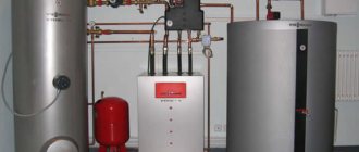
The most comfortable and most economical way to heat your home is to install underfloor heating. This method retains a significant amount of heat - up to 20-30% at a ceiling height of about 2.5 m and up to 50% at higher ceilings (3.5 m and higher). But a water heat-insulated floor is a rather complex engineering system, its device requires certain knowledge.
I welcome my regular reader and bring to his attention an article on what is the optimal distance between the pipes of a warm floor and what factors it depends on.
The advantages of heating a house with a warm floor are many:
- The entire room is heated, and in the most physiologically comfortable way - it is warmer below, cooler at head level.
- There is no strong convection, heat does not rise to the ceiling and is not wasted, therefore such heating is more economical.
- Dust and dirt do not collect on the heaters.
- Devices and communications do not take up space, curtains and furniture do not obstruct the construction of the warm floor and do not interfere with its work.
But comfortable heating is obtained only with proper installation and adjustment of the heating system. One of the main factors that determine the power of a warm floor is the distance between the heating pipes.
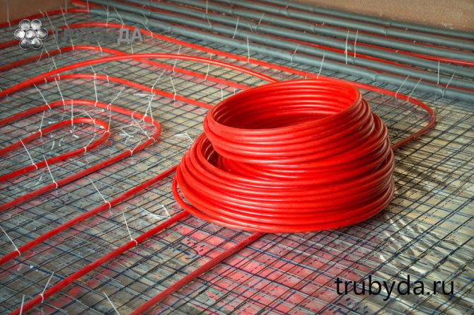
Common installation steps
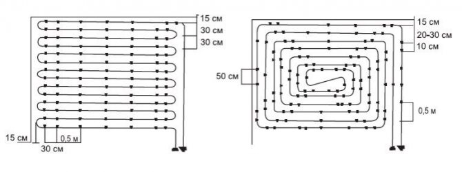
Usually the pipes are laid so that the distance between them is 100-300 mm. More precisely, the step is determined only after calculating the total length of the pipeline and determining the heating area (room area minus the area of bulky furniture). In practice, the distance is calculated approximately (see below), and then a scheme for laying a warm floor is drawn and the step is specified.
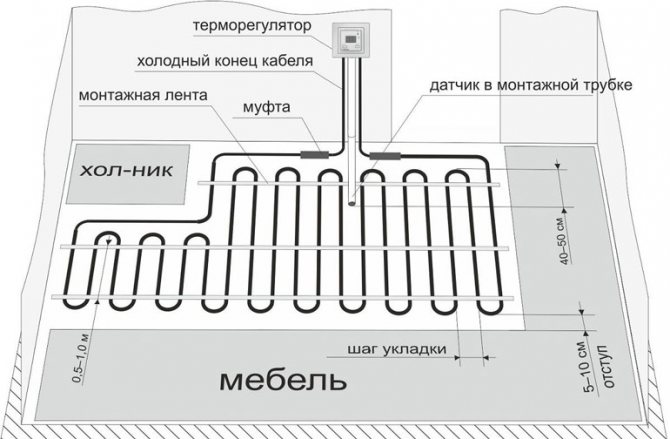
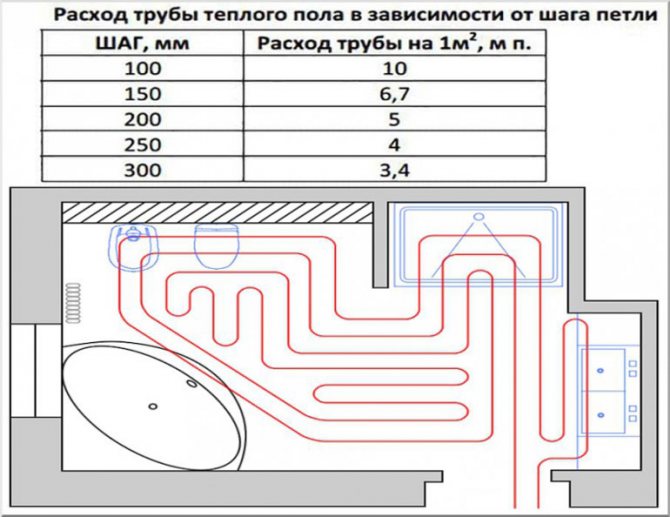
The approximate distance in bathrooms is 100-150 mm, in living quarters - 250 mm, 300-350 mm in corridors, lobbies, kitchens, utility rooms, storage rooms, etc. more in the rest of the room. Any method of placing warm pipelines can have a different pitch in different parts of the room.
How is the pipe length calculated?
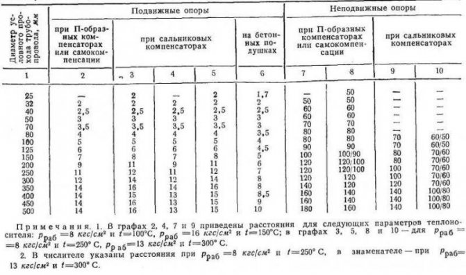
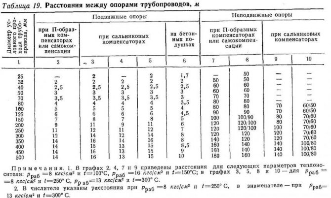
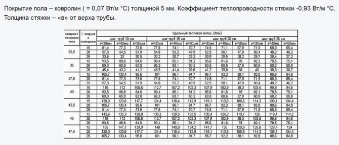
Traditionally, calculations assume that 5 m of pipe is sufficient to heat 1 m² of floor (see table above). The nominal distance will be 200 mm. Based on this ratio, you can calculate the nominal length of the entire pipeline: multiply the total area of the room by 5 and round up.
For corner rooms with one window, it is better to increase this length by 20% (by 1.2), with two windows - by 30% (by 1.3). For the northern regions of the Russian Federation, it is necessary to multiply the resulting length by another 20% (by 1.2).
For example, for a corner room with an area of 20 m² with two windows and in a cold region of Russia, the length of the pipeline will be:
This calculation uses the full area of the room without deducting the area of large pieces of furniture. This is done because the air above the sofas (and even cabinets) also needs to be heated, part of the heat is spent on heating the furniture itself. Calculated by the reduced area, the room will be cool, and in a small room cluttered with furniture it may be simply cold.
When buying, you need to add a small margin for turns and inaccuracies (6%, or a factor of 1.06) and double the distance from the collector to the room.
Determination of the maximum length of one contour
The maximum length of one circuit should under no circumstances exceed 100 m - otherwise the pump simply will not push the coolant into the circuit. And it is better to divide the one-hundred-meter circuit into two - the heating will improve, and with excessive heating, you can always adjust the heating of each circuit using a three-way valve in the manifold assembly.
Where can I find official information
SNiP 3.05.01-85 entitled "INTERNAL SANITARY AND TECHNICAL SYSTEMS" (incomplete name of the document) regulates in detail the laying of water supply pipes, including heating ones, as well as the relative position of the radiator, floor, underwater pipes.You need to pay attention only to some points, since the specified document is a universal paper for different types of plumbing, as the name implies.
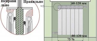
Radiator installation diagram
Section "HEATING" starts from point 3.18 and ends with number 3.33. The most significant items are 3.20 and 3.22. It is here that the relationship of the radiator to all elements of the room is described, as well as the distance between adjacent pipes.
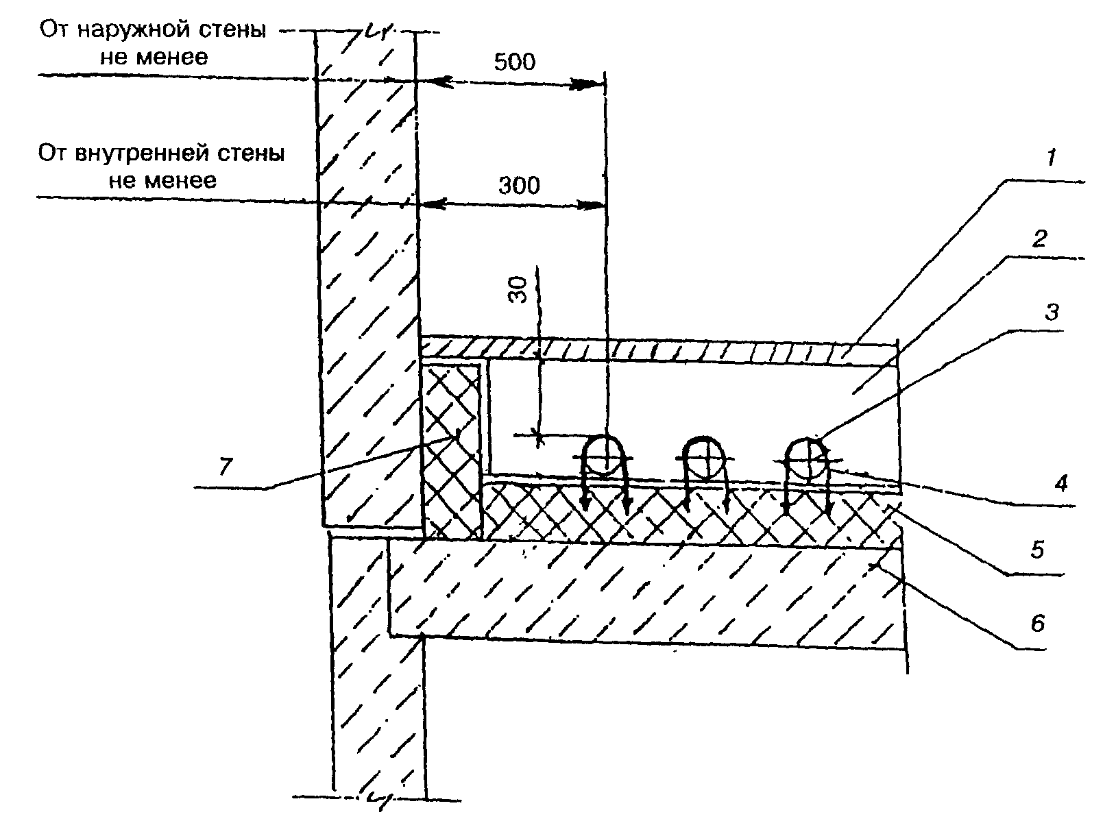
Distance from the wall
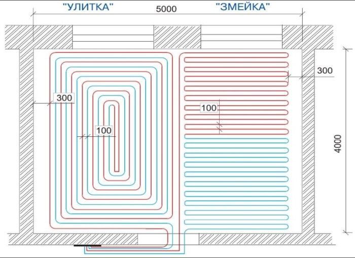
Styling forms
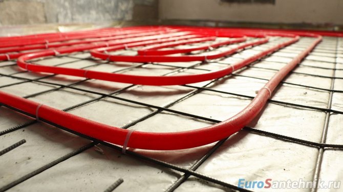
There are various ways of laying pipelines in a screed.
Snake
When laying in a snake, or meander, pipelines are placed in parallel. At the same time, the room heats up unevenly. The method is suitable for small rooms. The snake is used in a combined installation method - communications are laid along the outer wall and cut off cold air.
When laying with a snake, a short distance or additional heating (radiators) is required.
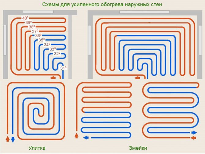
Corner snake
The pipe is laid along the outer corner, the next turns are laid in parallel so that the pipeline occupies a square. Suitable for heating corners. The double corner snake is used for rooms with three outer walls.
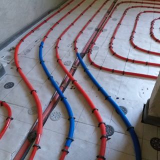
Double snake
The beginning and end of one heating circuit are laid in parallel. Of all the options for snakes, it provides the most uniform heating of the room.
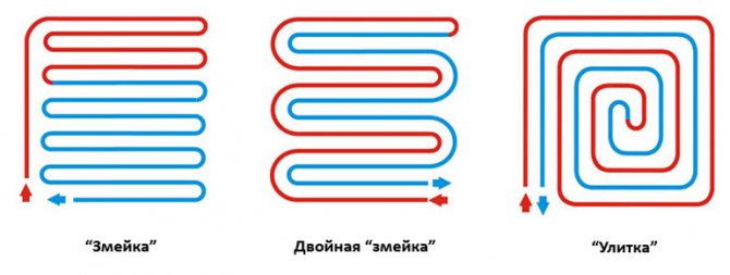
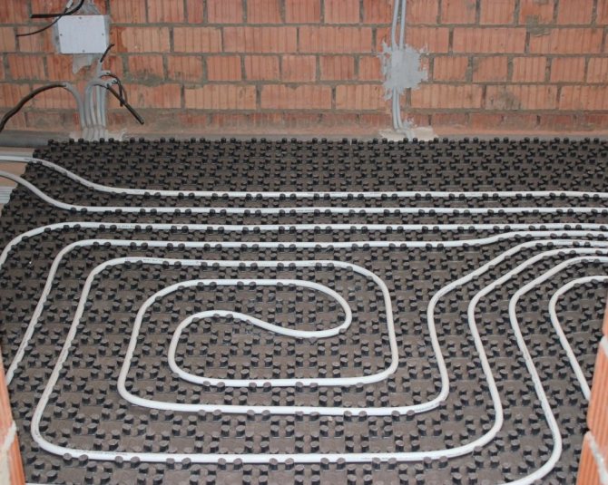
Snail
Otherwise, this method is called a snail, shell, spiral. The pipelines are laid in a spiral, ensuring the most uniform heating of the entire area. It is so convenient to place pipes in large rooms.
Which way is better
The combination of two installation options allows you to optimally arrange communications in the room. In large rooms, it is better to use a snail or combine it with a snake - lay several pipes with a snake near the outer wall, and arrange the pipes in a spiral over the rest of the area.
A snake against the outer wall will cut off the cold from the walls and windows. You can adjust this circuit to a higher temperature of the heating medium.
In small rooms, for example a bathroom, a corridor, a snake is optimal. In medium-sized rooms, there is a double snake. When laying pipes using the corner snake method, the room will warm up unevenly, the use of a corner snake is appropriate only when warming up the corners with combined laying.
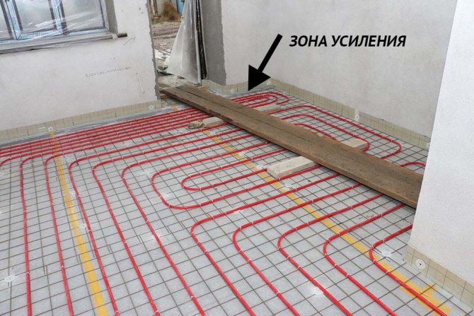
Often, combined options or a change in distance are used deliberately - to compensate for unheated areas (under upholstered furniture) or to heat a workplace, a play corner for children, etc. For example, it is better to heat a little more:
- The area near the desk, sewing machine or piano - there a person sits motionless and can freeze.
- Part of the room where children often and a lot play.
- Warm areas around the bed, sitting area with upholstered furniture in the living room.
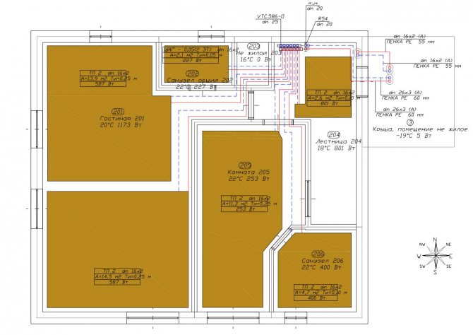
In any case, before installing with your own hands, you need to draw a pipeline laying diagram by calculating the length of the pipeline and the distance between the turns. Then arm yourself with a pencil and graph paper and draw a diagram taking into account the arrangement of furniture and the method of laying out the warm floor. At the same time, take into account the increase in the frequency of laying near upholstered furniture, beds and other places requiring heat.
The subtleties of laying and connecting pipelines can be seen in our video.
Installation of pipelines for heating systems
Main pipelines in the basement they are threaded and welded in the following sequence: first, the pipes of the return line are laid out on the installed supports, one half of the line is checked along a given slope and the pipeline is connected by thread or welding. Next, with the help of squeegees, the risers are connected to the main line, first dry, and then a flax strand, greased with red lead, is wound onto the pipe and again the risers are connected with the squeegees to the main line and the pipeline is strengthened on the supports. When installing highways attic wiring, first mark the axes of the highways on the surface of building structures and install suspensions or wall supports along the intended axes. After that, the main pipeline is assembled and fixed on hangers or supports, the lines are verified and the pipeline is connected by thread or welding; then connect the risers to the main line. When laying main pipelines, it is necessary to observe the design slopes, straightness of the pipelines, install air collectors and descents in the places indicated in the project. If the project does not contain instructions on the slope of the pipes, then it is taken equal to at least 0.002 with an ascent towards the air collectors. The slope of the pipeline in attics, canals and basements is marked with a rail, a level and a cord. At the installation site, according to the project, the position of any point on the pipeline axis is determined. A horizontal line is laid from this point and a cord is pulled along it. Then, along a given slope at a distance of 1.5 m from the first point, the second point of the pipeline is found. A cord is pulled along the two points found, which will determine the axis of the pipeline. Pipes passing through ceilings and walls are enclosed in sleeves with a diameter slightly larger than the pipe diameter, which ensures free extension of the pipes when temperature conditions change. It is not allowed to connect pipes in the thickness of walls and ceilings, since they cannot be inspected and repaired. Suspensions, brackets and supports must be such that free pipe extension is possible when heated.
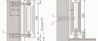
Indoor piping is laid open, when the surface of the pipes is used as heating and is taken into account when calculating the area of heating devices, and hidden - in special grooves, channels, shafts, monolithing them with a finishing solution or closing with frieze linings. All distribution lines must have a slope of at least 0.002. It is recommended to take a normal slope of at least 0.003 - 0.005. In systems with natural circulation, the slope of the pipes is set at least 0.01. To reduce unproductive heat losses, heating pipelines are covered with thermal insulation. The most common is thermal insulation, where mineral wool is used as insulation. It comes from the factory in the form of dimensional mats (rugs) or long mats 1.0-1.5 m wide. It is advisable to tie the auxiliary equipment with pipelines at the assembly site before its installation in place. Pipeline parts are assembled at the assembly site into separate units - blocks, which consist of shaped parts, fittings and straight pipes. All unions for connecting impulse pipelines, instrumentation and drains must be welded on the units. On the steam lines, special bosses are installed to measure the permanent deformation of the pipes. The geometric dimensions of each block are specified by measuring the physical dimensions of the sections of the pipeline route, and the mounting allowances are cut off. When assembling the blocks, the joints of individual parts are carefully prepared for welding. For joining pipes before welding, special devices are used.The gap between the butting edges of the parts is adjusted with rods to match the type of seam used. The displacement of the abutting edges should not exceed 0.5-1.5 mm with a pipe edge thickness of 10-16 mm, respectively; with a larger wall thickness, the offset should not exceed 3mm. The fracture of the pipeline axis at the joints of the parts is controlled with a ruler; it should not exceed 1-2 mm for each meter of its length. The inner surfaces of the pipelines are cleaned of dirt and corrosion products, and foreign objects are removed from the pipelines. After cleaning, the ends of the pipes are closed with temporary plugs. The fittings, if necessary, are subject to revision and hydraulic tests. Heating devices and an expansion tank must be installed in the building prior to piping installation. In many cases, the pipeline is installed simultaneously with the installation of heating devices. In this case, it is advisable to immediately mark the axes of the pipelines of the entire system. Then at the same time it is possible to carry out the installation of main pipelines and risers. The axes of the risers are marked on the walls with a plumb line and a cord rubbed with chalk after punching holes in the walls and ceilings. When marking on the walls in each floor, near the line broken off along the cord, the number of the riser and the diameter of the pipeline are inscribed. With a two-pipe heating system, only the axes of the hot water risers are marked. The supply riser is always laid on the right side, and the return pipe on the left. The distance between the axes of the supply and return of adjacent non-insulated risers with a diameter of up to 32 mm should be 80 mm with a tolerance of +/- 5 mm. The distance between the walls and the axes of the risers is taken as follows: 35 mm with openly laid non-insulated risers with a diameter of 15-32 mm and 50 mm with risers with a diameter of 40-50 mm; permissible deviation + 5mm. With concealed wiring, the risers should not be adjacent to the masonry. With open wiring, the risers are laid vertically with a tolerance of +/- 2 mm for each meter of the riser. For fixing two pipes to the wall, double clamps are used. When installing radiators with a building height of 500 mm or ribbed pipes, the clamps are embedded into the wall at a height of 1.5 m, and when installing radiators with a building height of 1000 mm - at a height of 2 m from the floor. Risers between floors are connected by squeezing and welding. The squeegees are installed at a height of 300 mm from the supply line. After assembling the riser and the connections, carefully check the verticality of the risers, the correctness of the slopes of the connections to the radiators, the strength of the fastening of pipes and radiators, the accuracy of the assembly - the thoroughness of stripping the flax strand at the threaded connections, the correctness of the fastening of the pipes, cleaning the cement mortar on the surface of the walls at the clamps. In order for pipes in clamps, ceilings and walls to move freely, clamps are made of slightly larger diameter than pipes.
Pipe sleeves are installed in the walls and ceilings. The sleeves should protrude a few millimeters from the floor. They are made from scraps of pipes or roofing steel. At a coolant temperature above 100 degrees C, pipes are also wrapped in asbestos. If there is no insulation, then the distance from the sleeve to wood and other combustible structures must be at least 100 mm. At a coolant temperature below 100 degrees C, liners can be made of sheet asbestos or cardboard. Do not wrap the pipes with roofing tar, as when using it, black spots will appear on the ceiling near the pipe passage. With an open laying of risers and installing devices in a niche, the connections are made directly. When laying pipelines hidden and installing devices in niches, as well as when installing devices near walls without niches and open laying of risers, liners are placed with ducks. If the pipelines of two-pipe heating systems are laid openly, the brackets when bypassing the pipes are bent on the risers, and the bend should be directed towards the room.With the hidden laying of pipelines of two-pipe heating systems, the brackets are not made, and at the intersection of the pipes, the risers are somewhat displaced in the furrow. To ensure that the fittings and fittings are correctly positioned during installation to avoid leakage, the threads must not be loosened in the opposite direction (unscrewed). In this case, with a cylindrical thread, unscrew the fittings or fittings, wind up the flax and screw it on again. Clamps are installed on the liners only if their length is more than 1.5 mm. When calculating heating devices, heat transfer from pipelines is taken into account. Therefore, it is important that the risers run in the rooms indicated in the drawing. During installation, the blocks are lifted with bridge cranes, winches or hoists, and the slinging points of the blocks are chosen so as to prevent pipe bending and damage to the fittings. To prevent the block from tipping over during lifting, and the slings not to interfere with its installation in place, before lifting to a great height, braces from a hemp rope are tied to the ends of the block, which make it possible to remove the block from obstacles that interfere with its lifting. To reduce stresses in the metal and forces acting on fixed supports and arising from thermal elongation of steam pipelines, cold stretching of pipes is used during installation. The length and location of such a stretching of the steam line are indicated on the assembly and assembly drawing. If a section of the pipeline is being mounted on which cold stretching is to be carried out, then at the time of installation between the abutting edges, a pipe section with a length equal to the length of the cold stretching is installed. This segment is temporarily fixed with clamps or on an electric tie.
Pipes of complex configuration in cramped conditions sometimes have to be mounted not in blocks, but in separate parts. In this case, the installation starts from the flanges on the equipment. When joining each subsequent part, check its position according to the assembly and assembly drawing and perform the necessary adjustment. The details of such pipelines are fixed on temporary supports and hangers, and upon completion of the installation of the corresponding pipeline unit, they are replaced with permanent ones. The temporary links and supports are removed after the load from the pipeline mass has been transferred to the permanent links and supports. So that the previously installed pipeline nodes do not interfere with the installation of subsequent ones, pipes of a larger diameter are first installed. Small-diameter pipelines are installed last. The steam extraction pipelines are connected to the equipment only after the final alignment of the last extraction, installation of permanent shims under the frames and tightening of the foundation studs. Docking of pipelines with nozzles is carried out on hangers so that there is a uniform gap between the abutting edges, and the load from the mass of the pipeline is distributed to the supports and hangers and is not transferred to the pipe. In the same way, they dock with equipment, especially with pumps, all flange connections of pipelines. The pipeline flange is centered with the heating equipment flange with the greatest uniform gap between them. Skewed flanges are not allowed.
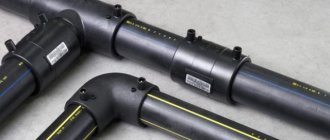
Is it possible to join a pipe for a warm floor
When laying a copper system in a screed, pipes will most likely have to be docked together. Such a connection is reliable and durable. The brazed connection of polypropylene pipes and welding of polyethylene using a thermistor coupling are also reliable. The issue is more complicated with the use of fittings for HDPE, PE-X and thermostable polyethylene (PE RT).
Press fittings can be used, although not desirable (anything can happen, any connection can leak). But when connecting pipelines to the manifold, press fittings are indispensable. It is not allowed to connect pipes with each other using push and compression fittings. The same goes for HDPE collet connectors.
It is advisable to use flexible pipes in one piece - this is more reliable.Drying the floor, repairing the lower room and breaking the screed in the event of a leak are more expensive.