Purpose of pressure regulators
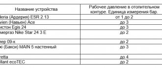
The devices are capable of performing a number of important functions simultaneously. The first is to prevent pressure build-up. Almost all household plumbing fixtures are capable of operating in a mode up to 3 atm. Exceeding this parameter is fraught with overloads for the water supply system at home. As a result, the service life of functional units on washing machines and dishwashers is noticeably reduced, and the reliability of connecting adapters and gaskets decreases.
Pressure regulators prevent water hammer. We are talking about sudden changes in water pressure arising from malfunctions of pumping equipment or improper use of valves. Water hammers can lead to very disastrous consequences, including pipeline ruptures and breakdowns of boiler units. Sometimes the pressure surges are so large that the boiler explodes.
Another useful feature is economical water consumption. By adjusting the water pressure, you can significantly reduce its consumption. For example, if the pressure is reduced from 6 to 3 atm, the savings can reach 20-25% (while opening the tap, a smaller jet will be released).
Hydraulic controllers help reduce noise when using mixers and taps. The reason for the annoying hum of the fittings lies in the increased pressure, due to which the water pressure after opening the valve acquires a boundary force. Thanks to the regulator, the water pressure becomes stable and decreases to optimal values.
In the event of a pipeline rupture, water losses will decrease, since the device reacts to a pressure drop by reducing the water supply. Basically, water supply systems of private houses are equipped with regulators (reducers), where they, together with a hydraulic accumulator, are switched to a circulation pump.
Features of devices
Water pressure regulators are presented in the plumbing market in several varieties. At the place of installation, the devices are divided into two groups:
- "To yourself." The flow voltage is stabilized in front of the reducer;
- "after myself". The water pressure is stabilized downstream of the installation point.
Regardless of the principle of operation, any pressure switch consists of the following structural elements:
- valve (piston). Serves as the core of the device;
- springs (membranes);
- housing. It can be cast iron, brass or steel.
In addition to the standard set of parts, some models are additionally equipped with a pressure gauge, a coarse filter, an air valve and a ball valve.
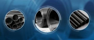
In terms of throughput, the regulators are divided into household (0.5-3 m3), commercial (3-15 m3) and industrial (over 15 m3).
Types, main parameters and dimensions
4.1 Types of cranes, functional purpose and scope should correspond to those indicated in table 1.
4.2 The regulating and shut-off assemblies of valves can be valve (B), plug (P), ball (W) and throttle (D) types.
Table 1
| Name | Crane type designation | Area of application, place of installation | Functional purpose |
| Maintenance control valve | MCT | Single-pipe heating systems in the enclosing sections | Consumer regulation |
| Control valve through passage | KRP | The same on eyeliners | Also |
| Control valve double adjustment | KRD | Two-pipe heating systems with connections | Assembly and consumer regulation |
| Erection control valve | KRM | Also | Mounting regulation |
| Shut-off valve | KZ | Any heating systems | Operational |
4.3 The main dimensions of the valves must correspond to the values indicated in table 2.
table 2
| Crane type | Nominal diameter, DN, mm | Length, mm, no more | Coupling end thread according to GOST 6357 |
| MCT | 15 | 55 | G1 / 2-B |
| KRP | 20 | 60 | G3 / 4-B |
| KRD | |||
| KRM | |||
| KZP | 15 20 | 55 60 | G1 / 2-B G3 / 4-B |
| KZSH | Up to 50 | 60 | G3 / 4-B |
Note: The height of manual control valves (from the supply line axis) should not exceed 85 mm.
4.4 The regulating devices of the taps in the closed position with a pressure difference before and after them of 1 kPa (0.01 kgf / cm2) should not let water pass more than 20 cm3 / min for a tap with a diameter of DN 15 mm and 30 cm3 / min for a tap with a diameter of DN 20 mm.
4.5 The coefficient of hydraulic resistance of the valves (in the open position of the regulating device) should not exceed the values indicated in Table 3.
Table 3
| Crane type | Nominal diameter, DN, mm | Heating agent consumption in the connection to the heating device, kg / h | Drag coefficient |
| MCT KRP KRD KRM | 15 | 50 to 100 | 3.0 to 3.5 * per pass "4.0" 4.5 per turn |
| 20 | » 300 » 600 | "2.5" 3.0 per passage "3.0" 3.5 per turn | |
| KZP | 15 | » 50 » 100 | » 0,5 » 1.0 |
| 20 | » 300 » 600 | » 0,5 » 1,0 | |
| KZSH | 15 | » 50 » 100 | » 0,15 » 0,5 |
| 20 | » 300 » 600 |
* For valves with a throttle control device - from 300 to 500
4.6 The symbol of the crane contains the name, designation of the type of the crane and the type of execution of its regulating device, the size of the nominal diameter and the designation of this standard.
In the absence of universality (in right- and left-hand mounting on heating devices), the designation of the valve is also supplemented with the corresponding letter (P or L).
Symbols examples
control valve with a diameter of DN 15 mm, ball type, universal:
KRPSh15 GOST 10944-97
three-way valve with a diameter of DN 15 mm in one-sided version for installation on the right inlet:
KRTSh15P GOST 10944-97
shut-off valve with nominal diameter DN 20 mm of plug type:
KZP20 GOST 10944-97
Types of regulators
According to the principle of operation, RVD are piston, diaphragm, flow-through, automatic and electronic.
Reciprocating
The simplest design water pressure valves (also called mechanical). Pressure adjustment is carried out by a compact spring-loaded piston by reducing or increasing the bore. To adjust the outlet water pressure, the device has a special valve: by rotating it, you can loosen or compress the spring.
The weaknesses of piston regulators include their sensitivity to the presence of debris in the water: piston clogging is the main cause of damage. To prevent such phenomena, a special filter is usually included in the gearbox kit. Another disadvantage is the large number of movable mechanical assemblies, which affects the degree of reliability of the gearbox. The piston device is capable of regulating the pressure in the 1-5 atm mode.
Membrane
Very reliable and unpretentious devices that make it possible to adjust the water pressure over a wide range (0.5-3 m3 / h). For living conditions, this is a very decent indicator.
The core of the device is a spring-loaded diaphragm: a self-contained sealed chamber is used for its installation to avoid clogging. The recoil from the compressing or expanding spring is transferred to a small valve, which is responsible for the size of the cross-section of the outlet channel. The cost of diaphragm restraints is quite high. Due to the complexity of replacement, this procedure is usually performed by experienced plumbers.
Flowing
A feature of this model of water pressure regulators is that there are no moving elements in it. This has a beneficial effect on the reliability and durability of the devices.
The pressure is reduced due to the intricacies of narrow channels. When passing through numerous turns, water is divided into separate branches, at the end again merging into one, but not so fast. In domestic applications, flow reducers can be found in irrigation systems. The disadvantage of the device is the need for an additional regulator at the output.
Automatic
Small unit consisting of a diaphragm and a pair of springs. Special nuts are used to change the compression force.When the inlet water has a weak head, this leads to a weakening of the membrane. The increase in pressure in the pipe provokes an increase in compression.
A spring forces the contacts on the automatic pressure reducer to open and close again. This, in turn, turns on and off the circulation pump of the forced water supply system. The design of automatic high pressure hoses basically duplicates membrane devices, differing only in the presence of two adjustment screws for setting the operating pressure range.
Electronic
A special mechanism monitors the water pressure in the pipe, for which a motion sensor is used. After processing the received data, a decision is made to turn on the pumping station. The electronic regulator will block the activation of the pump if the pipeline is not filled with water. The structure includes the main body, sensors, an electronic circuit board, a switching bushing (thanks to it, the supply wire is switched on) and threaded nipples for connecting to the system.
The stabilizer has a convenient display for displaying water flow characteristics. Mechanical regulators are sometimes not able to effectively protect the system from dry running, which is why it is necessary to constantly monitor it for the presence of water. In contrast, electronic models with a controller are able to constantly monitor the filling of water. Reducers of this type operate almost silently, reliably protecting all units from hydraulic shocks.
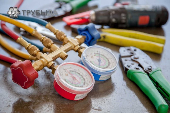
Customization and maintenance
Special standards for the operation of domestic water supply systems recommend the outlet water pressure in the range of 2-3.5 kg / cm2. This mode can only be obtained by adjusting the water pressure reducer. The speed of action of different models of RVD is different. The flow of the system provokes a decrease in the pressure force by about 1.5 atm (the exact indicator depends on the specifics of the circuit). After a few seconds, an increase in pressure is observed to a value below average. The ideal parameter of the output value should be inferior to the input value by at least 1.5 kg / cm2, otherwise this will lead to a noticeable deceleration of the speed of fluid movement through the pipes.
It is important to take these norms into account when adjusting water pressure reducers. To determine that the reducer is not working correctly, pair pressure gauges or a control fluid intake in front of the pressure regulator will help. It is possible to adjust the RVD only if the system is in working order and it has the required fluid pressure. Having created such conditions, in the course of rotation of the adjusting screws, you can easily determine all the changes in the indicators (this will be displayed on the pressure gauge). It is not recommended to carry out such manipulations without a measuring device, as this can lead to a violation of the factory settings.
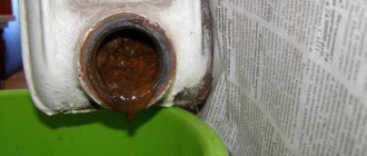
During the operation of the high pressure hose, it is necessary to control the pressure in the system. If the output parameters of the device cannot be adjusted, the diaphragm is most likely damaged. Sometimes water starts to seep through the joints on the case. Any signs of breakage serve as a signal to dismantle and disassemble the device. Most often, the membrane is injured by a rusty spring or stem. These assemblies, along with seals, can be found in repair kits available from your plumbing store.
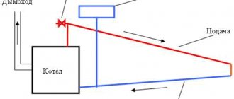
When installing a modern heating system, you cannot do without shut-off and control valves. The taps are installed in the places of boiler piping, water drain, air bleeding, bypass installation, circulation pump, heating radiators, etc. They are designed to regulate water flows and shut off in case of breakdown or replacement of some devices or elements in the heating system. Even the most balanced, perfect and reliable home heating scheme requires at least one tap installation - to drain the coolant. In reality, there should be much more locking elements.And what functional responsibilities each tap will have depends on its location in the heating system; structurally, they can also differ from one another.
How to buy
Ball valves both with handle control and with various configurations with controls and controls, for example, ball valves with pneumatic actuators or ball valves with an electric actuator can be purchased by contacting the central office of our company or one of the representative offices (see section Contacts ). There you can also get comprehensive advice and technical support regarding the use of products, selection, find out the price of a ball valve with a pneumatic drive, information about the availability or production time, etc. If a visit of a specialist to production is required for technical consultation, we can arrange it with pleasure. This service is free.
The main types of valves for the heating system
The basic principle of any faucet is to shut off and regulate the flow of fluid. This can be done with the help of several types of mechanisms that were used in the construction of cranes and gave them names. Each type of locking and adjusting device has its own advantages and disadvantages, which make it possible to better match them to a specific place in the heating system.
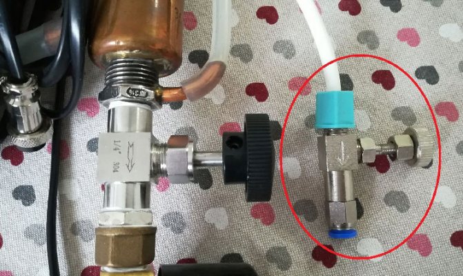
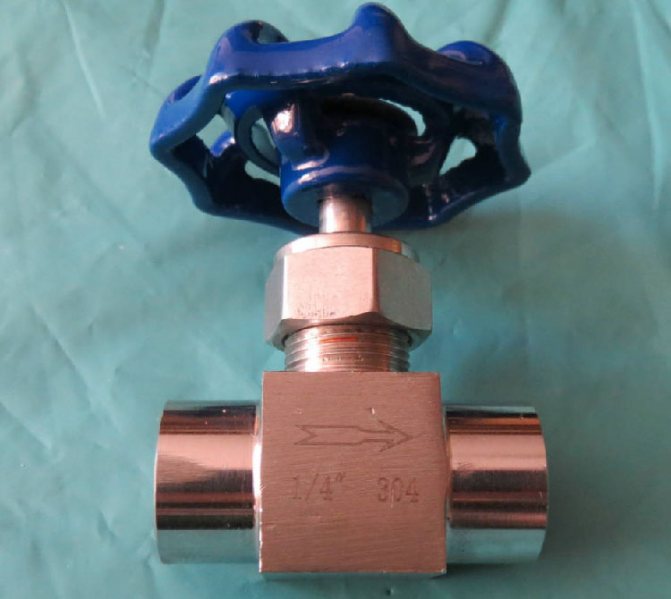
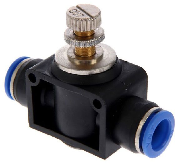
Important! Many valves are marked with an arrow on the body, which indicates the direction of fluid movement. Incorrect connection to the pointer can lead to breakage or malfunction of the locking device.
Each tap, even fully open, is an additional resistance in the path of the water flow, which reduces the head and pressure of the coolant, and also requires an increase in the power of the circulation pump.
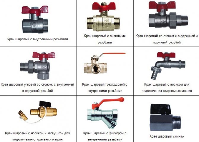
The most popular types of valves for the heating system by design and purpose:
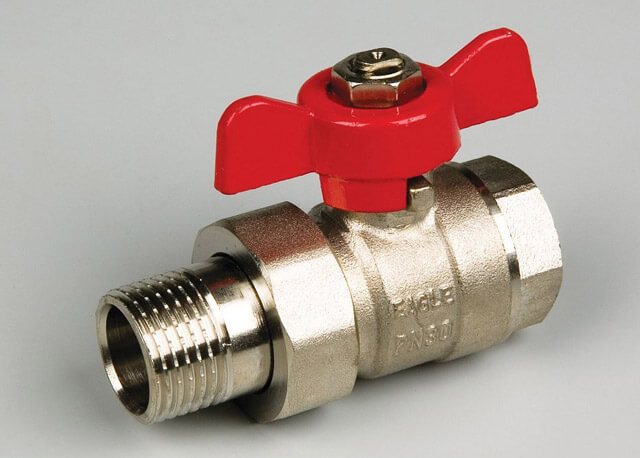
Ball - the name determines the type of construction. Inside there is a ball with a hole that can be rotated 90 °. This universal valve is used in those places where it is necessary to shut off the flow of liquid or gas in one motion. The features of this device are simplicity of design, low resistance to water flow, fast closing, not intended for adjustment. The shut-off ball is rotated using a butterfly valve or a lever;
Application area
Stainless or steel needle valves are used for the following purposes:
- in heating systems with a working pressure of the coolant up to 10 MPa;
- adjusting the supply of carbon dioxide, steam, liquid;
- throttling: in refrigeration plants, in industry where a cooling system is used;
- control of fluid inlet or outlet;
- vacuum installations and pumping units.
The main purposes of using needle cranes are:
- regulation of pressure in front of manometers for the purposes of its control, measurement, maintenance, system repair;
- creation of pipe branches from the central line to consumers, maintaining the operating pressure, but reducing the flow of the pumped medium;
- air release from heating systems.
Main areas of application:
- food;
- chemical;
- oil;
- in utilities;
- gas and heat supply systems.
Needle crane application
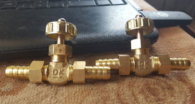
Features of "American" cranes
The scheme of connecting pipes using a threaded fitting, a gasket and a union nut, which received the slang name "American", in many matters of connecting shut-off valves is better than using a squeegee with a number of additional components (threads, couplings, lock nuts and counter threads). Also, with the old method of connection, very often it was necessary to rotate a pipe or a crane. This problem is not present now.The "American" is especially effective during the installation or replacement of radiators, heated towel rails, meters, expansion tanks and other units of the heating system. And you cannot do without it in hard-to-reach, inconvenient places where it is impossible to make a welding connection. To replace, dismantle or install any device included in the heating system, just turn the handle or valve to the “closed” position to shut off the coolant flow, and you can unscrew the union nut with a wrench, freeing any unit. From all of the above, we can conclude that the "American" is not so much a crane as a diagram of the connection of pipe parts and elements. This scheme can be used in any kind of shut-off valves, but most often the "American" is connected to a ball structure. Also, you can often find an American woman with a three-way valve equipped with a valve and equipped with an electric drive.
Important! There is an angular version of the "American", which has the same principle of action as the usual one - straight.
Water tap: features of selection and installation
The choice of pipeline valves must be approached responsibly, having studied not only the features of water taps, but also the installation procedure and troubleshooting methods. At the same time, it is important to take into account the purpose of the tap and the type of room in which it will be used: taps installed in bathrooms differ from kitchen taps not only in technical characteristics and appearance, but also in size and functional features.
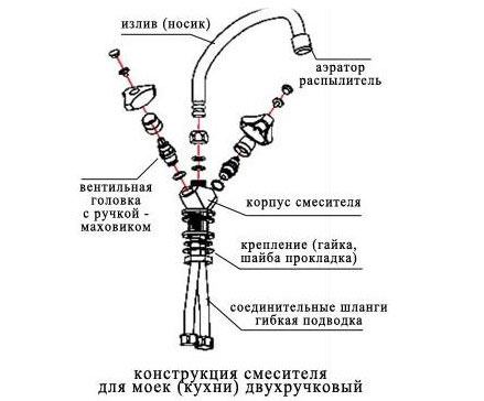
Operating principle
With a variety of tasks and design options, all cranes have similarities in structure and principle of operation.
Main details:
- shutter - adjusting mechanism;
- body with a through-hole and connecting pipes;
- control mechanism;
- a seal that ensures the tightness of the fit of the shutter to the body in the closed position;
- spout - a spout that supplies water to the outside (only available for water-taps).
When the control mechanism moves, the shutter moves inside the body, changing the throughput of the device. In one of the extreme positions of the control mechanism, the tap is in a fully open position, the water pressure is maximum. When the control mechanism is in the other extreme position, the shutter hermetically closes the passage opening in the body, the water flow is blocked.
Water enters the mixer from two pipes at once, both flows are regulated, when they are mixed, water of the required temperature is obtained.
Purpose of the structure
The water tap is a necessary part of the water supply network, which serves to regulate the flow of water. Different sections of the water supply system require different types of taps.
Water for household needs can be obtained by taps with a special spout - spout.
In the places where the home pipeline is connected to the centralized network and at the pipeline nodes, a simple shut-off valve is needed, the main task of which is to turn on and off the water supply, such taps do not have a spout.
If the house has hot water supply, then you need a mixer - a tap that mixes two streams in the right proportion.
Types of cranes
Cranes are distinguished by the type of body, shutter and control mechanism, as well as the presence of additional elements in the device.
Type of shell
By the type of housing, there are:
- straight lines - they are installed on key nodes of the pipeline and are used to adjust the pressure or turn off the water supply at the site, for example, during repairs;
- corner - installed in corner nodes, perform the same tasks as straight lines;
- distribution - the body has the shape of a tee with one inlet and two outlets, such taps are needed to cut one flow into several or redirect the flow from one water circuit to another;
- water-folding - have a spout and are used to receive water from a water supply system, while the body can be one-piece with a fixed spout or a prefabricated one - with a movable spout that rotates in a horizontal plane;
- mixers - tee-shaped water taps, with two inlets and one outlet, are used to mix flows from two water circuits in the required proportion.
Locking mechanism type
By the type of valve, ball valves and valves with a cone mechanism are distinguished.
- In the ball mechanism, the locking element has a spherical shape, the water flow is adjusted when the shutter is turned. If the opening of the shutter is installed parallel to the flow of water, the tap is open, if it is perpendicular, it is closed.

- In a tap with a cone mechanism, the through-hole is curved. An O-ring is horizontally located at the bend. When the valve or lever moves, the cone-shaped valve moves vertically downward or upward through this ring. In the extreme upper position of the shutter, the valve is open, in the extreme lower position, the ring and the shutter are hermetically connected and the valve is closed.
Control mechanism type
By the type of mechanism, the crane can be:
- single-valve,
- two-valve,
- single lever.
Each of the devices differs in how the locking mechanism is activated.
Single valve taps
Single-valve taps in the water supply system are used to regulate the flow in the pipeline nodes or to receive water from one water circuit, for example, drinking water or irrigation water.
The control mechanism consists of the following parts:
- the head is a lamb or handle, this is the outer part of the mechanism, the impact on which sets the internal parts in motion;
- axle box - a body, inside which the working parts of the control mechanism are located;
- a locking washer that fixes the valve on the tap;
- cap on the head covering the washer;
- stem - a part that transfers the force from a rotating wing or handle to the bolt;
- oil seal - a seal between the stem and the axle box;
- coupling with guides;
- gasket between the valve and the valve body.
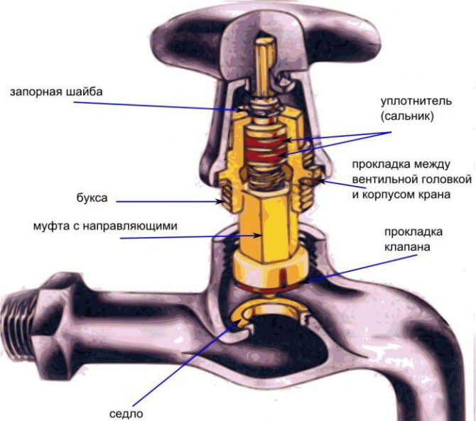
When the valve head is turned, the stem drives the shutter. In this case, the conical valve moves progressively up or down, and the ball valve rotates around its axis. The valve control mechanism is simple and reliable, and since it is not part of the crane, in the event of a breakdown, it can be repaired or can be completely replaced.
Two-valve taps
Two-valve taps are mixers that are used in houses with centralized hot water supply or in the presence of a water heater.
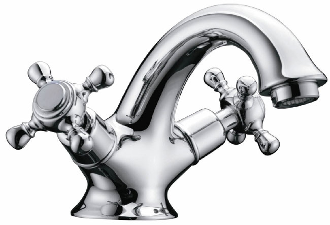
The control mechanism has the same structure as the single-valve valve. One valve regulates the flow of cold water, the other - hot.
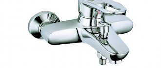
Single-lever devices
Single-lever taps - an alternative to one- or two-valve taps, have become popular as mixer taps due to their ease of operation. To obtain the required pressure, the lever can be lowered or raised by moving the lever to the left or right to regulate the temperature.
Single-lever valve arrangement:
- lever arm;
- ball valve with three holes;
- control rod;
- pin or screw securing the lever;
- stub;
- crane body;
- lid in the form of a truncated hemisphere;
- seal between parts.
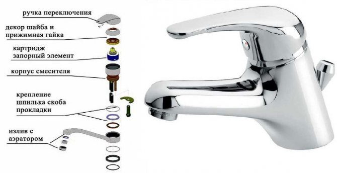
With appropriate action on the lever, the ball valve rises and falls or rotates. In this case, the holes in the ball change their position relative to the outlets of the water supply pipes and the faucet spout, adjusting the water pressure from each pipe.
Cranes equipped with additional elements
Crane manufacturers complement the device with a variety of elements:
- thermostats,
- touch panels,
- photocells,
- water opening sensors.
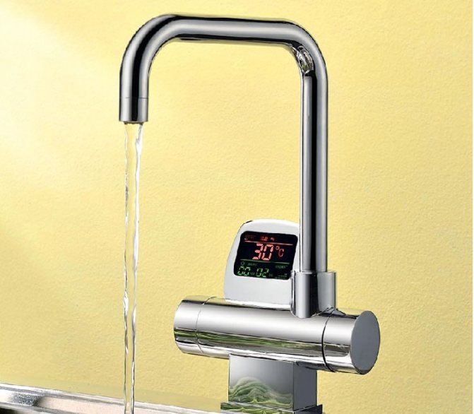
The faucet with a thermostat has a screen that displays the temperature and water pressure, and two regulators.The first regulator is connected directly to the ball mechanism and changes the water pressure, the second, which serves to regulate the temperature, is connected through a thermocouple.
The touch panel built into the tap allows you to adjust the water flow with a simple touch, there is no need to turn the valve or turn the lever - the electronic system automatically adjusts the pressure and temperature.
A non-contact crane is equipped with a photocell that reacts to the appearance of an object under the nose. The photocell sends a signal to the regulating mechanism that turns on the water. As soon as the reason for switching on disappears from the field of view of the sensor, the water turns off.
Such control of the water supply allows more economical use of the resource and minimizes direct human contact with the faucet, which makes such faucets more hygienic compared to conventional valve and lever valves.
How to choose a crane?
To choose the optimal design of the locking mechanism, you need to answer a number of questions:
- what is the purpose;
- in what room and with what plumbing fixture in combination it will work;
- will the installation and maintenance be done by hand or will a specialist be invited;
- additional functionality of the crane.
Note! Common to cranes used in a residential building is the presence of a divider installed at the outlet. The divider evenly distributes and directs the water flow and catches small debris brought from the mains.
Taps that are installed in sanitary rooms and kitchens have different functional features, the requirements for the size and design of parts also differ depending on the purpose of the room.
Bathroom faucet
The mixer in the bathroom, in addition to the basic functions, must switch the flow between the faucet spout and the shower, that is, it must have a shower hose and an additional switch lever.
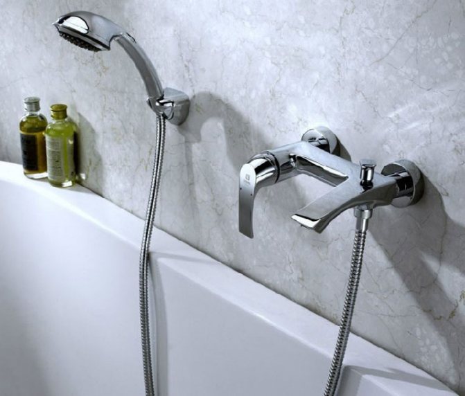
For comfort while taking a shower, you need to fine-tune the temperature setting. The mixer valves or lever should rotate smoothly, without force.
If a sink is installed next to the bathroom without its own tap, then choose faucets with a swivel spout.
The length of the spout is adjusted to the size of the sink: if the spout is too short, it will not reach the sink, if it is too long, water will flow from it past the sink.
Kitchen faucet
In this room, you can do with the simplest valve tap, but if there is hot water, a mixer is needed. Further complication of the design depends on the desires and needs of the people living in the house.
Since the dishes and products that need to be washed have different shapes and sizes, it is desirable that the spout of the faucet can be turned at least in a horizontal plane - any collapsible faucet gives such an opportunity.
In the kitchen, you can install a faucet-bracket or a combined faucet with a hose - they are equally convenient for use directly above the sink, and for washing the stove, table or refrigerator.
Installation and troubleshooting
Most valves are sold pre-assembled, so mounting the device to a pipeline is fairly straightforward.
Installation or replacement of a water tap
- Turn off the water in the room.
- Unscrew the union nuts with which the mixer is attached to the water supply pipes.
- Remove the old mixer, remove the old insulating material.
- Clean the edges of pipes, reducing sleeves and union nuts from dirt, scale and rust.
- Wrap tow or fum tape on the threads of the adapter sleeves, or put on gaskets made of rubber or leather.
- Align the mixer inlet pipes flush with the water supply pipes, tighten the union nuts.
- Cover joints with silicone sealant.
- Turn on the indoor water supply.
- Check the valve performance by gradually unscrewing the valves.
Troubleshooting crane operation
Wear of parts, clogging of the mechanism or installation errors can cause malfunctions of the crane.
Most faults can be fixed by yourself.
| Problem | Cause | Decision |
| faucet sprays water | the splitter is clogged or burst | unscrew the nozzle head, clean or replace the diffuser |
| water leaks at the junction of the tap with the pipeline | the tightness of the connection is broken or the thread of the union nut is torn | replace insulating material or nut |
| water drips or leaks from a closed tap | the shutter is worn out, the gasket between it and the body or the walls of the mixer | replace the shutter mechanism (sold separately) or gaskets, if it does not help, replace the mixer |
| water leaks from a valve or lever | the control mechanism or one of its parts is worn out | replace valve or damaged part: replace worn packing, gasket or stem with stripped thread |
Replacement of parts of the control mechanism or the crane itself is carried out without disconnecting the water supply. To disassemble it, remove the plug, unscrew the lock nut or screw and remove the control head.
In the event of a malfunction in the valve mechanism:
- Carefully remove the stuffing box winding with a thin knitting needle or awl.
- If the rod breaks, a new one is installed.
- A linen thread is wound on the stem at the junction with the axle box.
If there is a problem with the bolt mechanism:
- Remove the valve.
- Carefully remove the valve and worn gaskets.
- Clean the insides of the tap.
- Install gaskets and a shutter.
After completing all the manipulations, assemble the faucet, tighten the lock nut or screw and turn on the water.
Note! If all troubleshooting options have been tried, but the problems in the mixer operation have not been resolved, you will have to call a plumber.
Features of thermocontrol valves
The principle of operation of mechanical, electronic and electric thermostats is the same. They operate a valve that regulates the flow of the heating medium through the radiator. Thermal sensors of electronic taps are placed far outside the body, and measure the air temperature in those places in the room that are of interest to the consumer. In this way, they are better than mechanical and electrical ones, which determine the ambient temperature in the immediate vicinity of the heater. Also, the electronic system allows the temperature to be controlled remotely using a server.
In each system, consisting of pipes connected in series, there are sections where it is periodically necessary to shut off the flow of the working medium. For this, different types of shut-off and control valves are used. In high pressure systems, a needle valve is used as this mechanism.
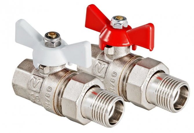
Ball Valves
The valves are cheap, but at the same time ineffective regulating devices. Ball valves are often installed at the entrance to the radiator, with the help of which the water flow is regulated.
But this equipment also has a different functionality - shut-off valves. Valves are used to completely shut off the flow of coolant in the system. For example, in the event of a heater leak, ball valves located at the inlet and outlet of the radiator allow repairs to be carried out without interrupting the heat supply and draining the liquid.
Ball valves do not regulate heating batteries in the apartment. They have only two positions - completely closed and open. The intermediate location only brings harm.
The fact is that inside such a faucet there is a ball with a hole, which in its normal position is not threatened, but in all other situations the solid particles present in the coolant grind it off and pieces break off from it. As a result, the tap will not be airtight and in the "closed" position water will continue to flow into the battery, which is fraught with big troubles in the event of a device leak.
If one of the property owners decided to do everything to manage the radiators using ball valves, it must be remembered that they must be installed correctly.
This method is usually used in apartment buildings. If the wiring is single-pipe vertical, then a hot water pipe enters the room through the ceiling and a radiator is connected to it (read: "Correct adjustment of heating batteries in an apartment - comfort in the house and saving money"). The pipeline leaves the second entrance to the device and goes through the floor to the room below.
In this case, it is necessary to correctly install the valves, since the installation of a bypass is mandatory. The bypass pipe is needed so that when the liquid flow to the radiator is closed, the coolant continues to circulate in the common house system.
In some situations, the tap is located on the bypass in order to change the amount of water passing through it and thereby adjust the heat transfer of the battery. To ensure greater reliability of the heating system, at least three taps are installed: two will be cut-off on the radiator and operate normally, and the third will become regulating.
But here we must not forget what position the devices are in. Otherwise, you can completely block the riser and it will not be possible to avoid both the cold in the apartment, as well as unpleasant showdowns with the neighbors and representatives of the management company.
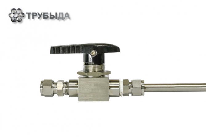
Purpose and application
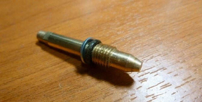
The needle valve is part of the shut-off and control valves. Such valves are installed on pipelines with a liquid, viscous or gaseous internal medium. They are distinguished from other types of valves by the structure of the lower part of the stem, which directly blocks the lumen. A needle valve has a stem that is tapered downward, making it look like a needle.
The valve consists of the following parts:
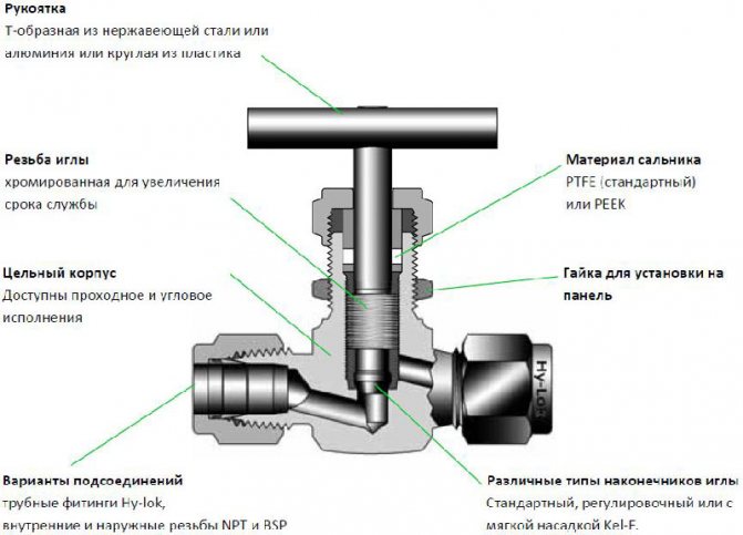
The principle of operation of the needle valve is simple: when the handle is rotated clockwise, the stem with the spindle is set in motion, while the spindle is screwed into the thread of the body and blocks the lumen. When rotating in the opposite direction, the stem rises and the gap is cleared. Such parts are installed on pipelines of both small and large diameters.
It is interesting! A distinctive feature of the needle valve is the structure of its spindle, which tapers conically downward. Its lower part is sharp and resembles a needle. Another feature of this mechanism is the ability to withstand significant pressure from the working environment.
The needle valve is used in systems for any purpose. It is irreplaceable in two cases.
- The first is to regulate the flow upstream of the pressure gauge. A pressure gauge is a device designed to measure the pressure in a system. It needs periodic maintenance. In addition, sometimes pressure gauges fail and lead to depressurization of the system. A needle valve is installed in front of the pressure gauge, which smoothly shuts off the flow if necessary. This ensures tightness in the system, even if the pressure gauge is faulty or during maintenance.
- The second case when a needle valve is irreplaceable is pipelines with high internal pressure. This device is capable of withstanding high pressure. Some types of needle valves are designed to operate at pressures up to 40 MPa. The device allows you to smoothly shut off the flow, preventing large pressure fluctuations in the system.
Types of needle valves
Valves of this type differ in several parameters. By design, there are three types of devices:
Shut-off valves are capable of completely shutting off the flow. They are the most resistant to high pressure and temperature, but their service life is short. These valves often contain liquids and gases, which can corrode the metal. Use shut-off valves on large highways.
Regulating needle valves are used when it is necessary to change the properties of the internal working environment. For example, reduce pressure or volume. The area of their application is pipelines of small diameter with a liquid medium.
Balancing valves are designed to regulate hydraulic resistance. In other words, they redirect the flow of fluids from one pipe to another, keeping the balance of volume, pressure, velocity or temperature at a given level. They are often installed on heating systems.
By design features, valves are distinguished:
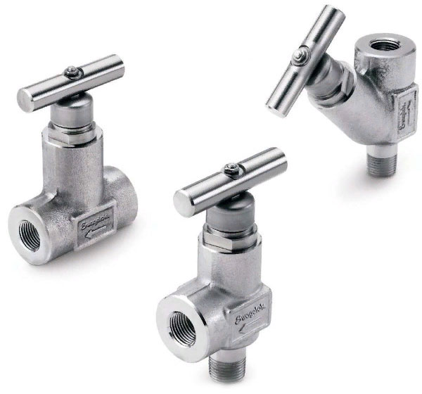
Straight-through valves are installed on pipelines in places where pipes are directly connected. They are relatively large compared to the pipe size. Due to the design features, stagnation often occurs in such mechanisms, they must be periodically cleaned.
Angle valves are used where pipes are at an angle to each other. For example, if the pipeline turns to form an elbow. An angle-type needle valve is installed at the turning point. They come in different diameters and are designed for systems with any interior environment.
Direct-flow structures are distinguished by their relatively large length and weight. In everyday life, they have not found widespread use, despite a number of advantages, including the lesser possibility of stagnation inside the mechanism. They are used as control valves in oil pipelines.
By the method of ensuring the tightness of the system:
One of the elements of the stuffing box valve is a seal, which prevents the working medium from escaping to the outside, regardless of the position of the stem. This option is not always reliable from the point of view of tightness.
Bellows valves use vacuum as the sealing medium. Vacuum spacers are often used in high pressure systems. They are more reliable and less likely to leak.
Advantages and disadvantages
Despite the large number of varieties, all needle valves have common positive and negative characteristics.
Note! Needle valves are always made of metal, sometimes they have a plastic handle. The valves are capable of withstanding temperature conditions from -20 to + 200 ° С. Depending on the type of valve, the maximum pressure at which they can operate reaches 15 to 45 MPa.
The advantages of needle valves include:
- the ability to withstand large temperature drops;
- the ability to function under conditions of increased pressure;
- simplicity of design, the possibility of self-installation and maintenance;
- resistance to corrosion with the appropriate quality of metal parts;
- durability - the service life reaches 15 years;
- smooth flow shut-off, which is important for high pressure systems, where a sharp shutdown can provoke a breakthrough;
- the tightness of the device in relation to the external and internal environments with the complete lowering of the stem;
- work with a viscous internal environment in a free-flow pipeline.
The disadvantages of needle taps include:
- high hydraulic resistance, which leads to hydraulic losses of kinetic energy, in other words, it is more difficult for a working medium to pass through a section with a needle valve than through a smooth pipe;
- inability to work with a viscous internal medium under high pressure conditions;
- a relatively large section of pipe replacement (a large indicator of the face-to-face length), which affects the physical properties of the working environment;
- the need for periodic cleaning of some types of products from liquids that get inside;
- work only with one-way flow, impossibility to redirect the flow in the other direction;
- the difficulty of replacing the valve when it fails, since this part is non-removable.
Control.
In order to reduce the number of errors in the selection, ordering, installation and connection, as well as to save our customers' time on assembly and setup, we offer a whole range of ready-made solutions in terms of control and monitoring of ball valves. When creating the nomenclature, we took into account the wishes of our Customers and included in the nomenclature a large number of ball valves complete with the most demanded control and monitoring bodies in various modifications, such as pneumatic actuator, electric actuator, handwheel, position sensors and valve blocks. Our task was to make it as easy as possible for our Customers to select components when forming the final product. Such products are supplied assembled, completely ready for use, having passed all the necessary adjustments and testing.
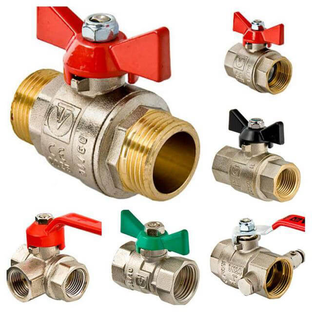
| Ball valves with handle. This type of control is applicable to most models of ball valves with nominal diameters up to 200 mm. However, it should be borne in mind that with high flow pressure on large ball valve diameters, the torque required to turn the ball can be high and significant physical effort is required to control. Also, the ball valve handle can be equipped with a mechanical lock to prevent unauthorized or accidental rotation. Some models can be equipped with a stem extension up to 100 mm. | |
| Gearbox with steering wheel Installed on a model where the torque required to operate the ball valve is higher than that which can be achieved with the handle, or in cases where it is necessary to guarantee the rotation of the ball valve with little physical effort. As with the handle, the gearbox can be fitted with a mechanical lock to prevent unauthorized or accidental rotation. All geared ball valve models can be equipped with a stem extension up to two meters | |
| Ball valve with handle (gearbox) and position transmitter Ball valves with a handle and gearbox, with the exception of some models, can be equipped with a limit switch block for remote receiving information about the position of the ball valve. Our company can offer more than one hundred variants of limit switch blocks in plastic, aluminum or stainless steel casing, equipped with electromechanical or inductive sensors from various manufacturers. These products are supplied both in general industrial design and in explosion-proof (intrinsically safe circuit, explosion-proof enclosure). Climatic performance can be from -60 ° C environment | |
| Ball valves with pneumatic drive. Most of the models of ball valves offered by our company can be equipped with a double-acting or spring-return pneumatic actuator. Valves equipped with a single-acting pneumatic actuator (with spring return) can, depending on the customer's requirements, be supplied in a normally open or normally closed version. The actuators can be matched to any control pressure. The execution of drives can also be different both in terms of climatic performance (from -60 ° C to + 150 ° C of the environment), and in terms of corrosion resistance. | |
| Ball valves with pneumatic actuator and limit switch block As in the case of manually operated ball valves, we offer more than one hundred variants of limit switch blocks in plastic, aluminum or stainless steel casing, equipped with electromechanical or inductive sensors from various manufacturers, both in general industrial and in explosion-proof (intrinsically safe circuit, explosion-proof enclosure) execution ... Climatic performance can be from -60 ° C environment. | |
| Ball valves with pneumatic actuator and handwheel The use of a handwheel is necessary when it is required to rotate the shut-off valves in the absence of a control signal, for example, in the event of a loss of compressed air, loss of an electrical signal to control the valve, etc. The use of handwheels can be especially relevant in the case of ball valves or butterfly valves equipped with pneumatic actuators with spring return, since in this situation it is impossible to rotate and fix the valves without using a handwheel. | |
| Ball valves with pneumatic actuator and valve Valbia valve-mounted pneumatic actuators can be equipped with monostable or bistable pneumatic control valves with electro-pneumatic or pneumatic control. Depending on the type of actuator and the requirements of the technological process, the valves can operate in 5/2 or 5/3 (for double-acting pneumatic actuators) or 3/2 (for single-acting pneumatic actuators). The valves are supplied in both general industrial and explosion-proof (intrinsically safe circuit, explosion-proof enclosure) execution. Climatic performance can be from -60 ° C environment. | |
| Various assembly options. Ball valves can be equipped with various combinations of controls and controls shown above. Our specialists will be able to select the optimal configuration based on the requirements of the Customer. | |
| Ball valves with electric drive Ball valves can be equipped with electric drives of various manufacturers based on the wishes of the Customer and the requirements of the technological process. Valbia actuators are used by default in the general industrial version. Explosion-proof electric actuators from such manufacturers as Auma, Rotork, Bernard, etc. can also be used. Climatic performance can be from -60 ° C environment. | |
What to consider when choosing a device?
Before purchasing a needle valve, it is necessary to determine on which section of the pipe it will be located, what is its diameter and the physical characteristics of the internal environment... The size of the valve must correspond to the diameter of the pipe, it is desirable that they are made of materials of the same name.
In addition, an important characteristic to consider is the pressure under which the liquid or gas moves through the pipe. At pressures up to 15 MPa, any needle valves can be installed. In the event that the pressure of the working medium exceeds this indicator, only two types of needle valves can be used. They are produced under the markings VI and VT-5. These types can withstand pressures up to 45 MPa.
The direction of the valve must be indicated, allowing you to determine which part of it is in contact with the leading section of the pipe, and which with the outlet. When properly installed, the valve shuts off the flow during clockwise rotation of the handle, and opens counterclockwise.
All parts of the device must be intact. Sites of minor scratches, coating chips or cracks in the future may reduce the service life.
When purchasing a valve, you should check how the handles rotate, how the stem and spindle behave. Rotation should be carried out with little resistance, the stem only move up and down. There should be no extraneous movements to the sides.In a working mechanism, when the spindle reaches the maximum lowering, the handle does not scroll.