If you pay enough attention to the comfort in the house, then you will probably agree that air quality should come first. Fresh air is good for your health and thinking. It's not a shame to invite guests to a room that smells good. Airing every room ten times a day is not an easy task, isn't it?
Much depends on the choice of the fan and, first of all, its pressure. But before you can determine the fan pressure, you need to familiarize yourself with some of the physical parameters. Read about them in our article.
Thanks to our material, you will study the formulas, learn the types of pressure in the ventilation system. We have provided you with information about the total head of the fan and two ways in which it can be measured. As a result, you will be able to measure all parameters yourself.
Ventilation system pressure
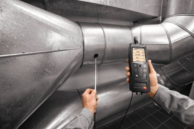
For ventilation to be effective, the fan pressure must be correctly selected. There are two options for self-measuring the pressure. The first method is direct, in which the pressure is measured in different places. The second option is to calculate 2 types of pressure out of 3 and get an unknown value from them.
Pressure (also - head) is static, dynamic (high-speed) and full. According to the latter indicator, there are three categories of fans.
The first includes devices with a head <1 kPa, the second - 1-3 kPa and more, the third - more than 3-12 kPa and above. In residential buildings, devices of the first and second categories are used.
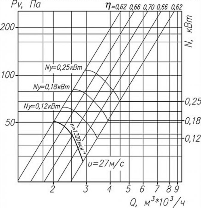
Aerodynamic characteristics of axial fans on the graph: Pv - total pressure, N - power, Q - air flow, ƞ - efficiency, u - speed, n - rotation frequency
In the technical documentation for the fan, aerodynamic parameters are usually indicated, including the total and static pressure at a certain capacity. In practice, the "factory" and real parameters often do not coincide, and this is due to the design features of ventilation systems.
There are international and national standards aimed at improving the accuracy of measurements in laboratory conditions.
In Russia, methods A and C are usually used, in which the air pressure after the fan is determined indirectly, based on the installed capacity. In different techniques, the outlet area includes or does not include the impeller sleeve.
Why raise the pressure
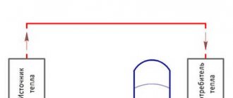
The head in the supply line is higher than in the return line. This difference characterizes the efficiency of the heating operation as follows:
- A small difference between the supply and return makes it clear that the coolant successfully overcomes all resistances and gives the calculated amount of energy to the premises.
- An increased pressure drop indicates increased section resistance, decreased flow rate, and excessive cooling. That is, there is insufficient water consumption and heat transfer to the rooms.
For reference. According to the standards, the optimal pressure difference in the supply and return pipelines should be within the range of 0.05-0.1 Bar, maximum - 0.2 Bar. If the readings of 2 pressure gauges installed on the line differ more, then the system is designed incorrectly or needs repair (flushing).
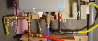
To avoid a high differential on long heating branches with a large number of batteries equipped with thermostatic valves, an automatic flow regulator is installed at the beginning of the line, as shown in the diagram.
So, overpressure in a closed heating network is created for the following reasons:
- to ensure the forced movement of the coolant at the required speed and flow rate;
- to monitor the state of the system using a pressure gauge and to recharge or repair it in time;
- the coolant under pressure heats up faster, and in the event of an emergency overheating, it boils at a higher temperature.
We are interested in the item of the second list - the readings of the manometer as a characteristic of the health and efficiency of the heating system. It is they who are interested in homeowners and apartment owners who are engaged in self-service home communications and equipment.
Formulas for calculating the fan head
The head is the ratio of the acting forces and the area to which they are directed. In the case of a ventilation duct, we are talking about air and cross-section.
Channel flow is uneven and does not flow at right angles to the cross section. It will not be possible to find out the exact head from one measurement; you will have to look for the average value over several points. This must be done both for entry and exit from the ventilating device.
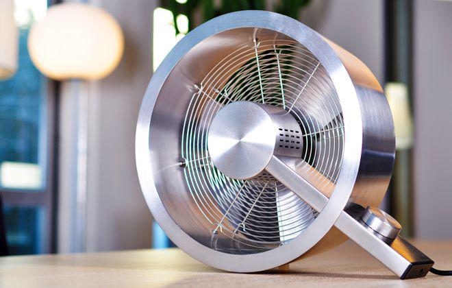
Axial fans are used separately and in air ducts, they work effectively where it is necessary to transfer large air masses at a relatively low pressure
The total fan pressure is determined by the formula Pп = Pп (out.) - Pп (in.)where:
- Pп (out) - total pressure at the outlet from the device;
- Pп (in.) - total pressure at the device inlet.
For the static pressure of the fan, the formula differs slightly.
It is written as Pst = Pst (out) - Pp (in), where:
- Рst (out) - static pressure at the outlet of the device;
- Pп (in.) - total pressure at the device inlet.
The static head does not reflect the required amount of energy to transfer it to the system, but serves as an additional parameter by which you can find out the total pressure. The latter indicator is the main criterion when choosing a fan: both home and industrial. The drop in total head reflects the energy loss in the system.
The static pressure in the ventilation duct itself is obtained from the difference in static pressure at the inlet and outlet of the ventilation: Pst = Pst 0 - Pst 1... This is a minor parameter.
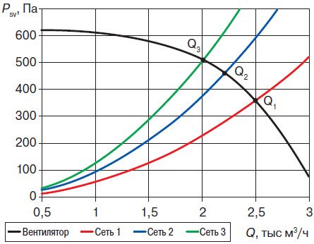
Designers provide parameters with little or no clogging in mind: the image shows the static pressure discrepancy of the same fan in different ventilation networks
The correct choice of a ventilation device includes the following nuances:
- calculation of air consumption in the system (m³ / s);
- selection of a device based on such a calculation;
- determination of the output speed for the selected fan (m / s);
- calculation of device Pp;
- measurement of static and dynamic head for comparison with total head.
To calculate the points for measuring the pressure, they are guided by the hydraulic diameter of the air duct. It is determined by the formula: D = 4F / P... F is the cross-sectional area of the pipe, and P is its perimeter. The distance for locating the measuring point at the inlet and outlet is measured with the number D.
Exceeding the limit value of the coolant pressure
If the operation process is accompanied by frequent "explosions" of the safety valve, the possible causes of this should be analyzed:
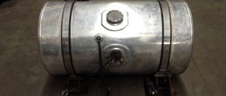
- underestimated expansion tank capacity;
- overestimated setting pressure of gas / air in the tank;
- incorrect installation location.
The presence of a tank with a capacity of 10% of the full capacity of the heating system is almost one hundred percent guarantee of the exclusion of the first reason. However, 10% is not the minimum possible capacity. A well-designed system can work normally even at a lower value. However, only a specialist who knows the methodology of the corresponding calculation can determine the sufficiency of the tank capacity.
The second and third reasons are closely interconnected.Suppose that the air / gas is pumped to 1.5 bar, and the location of the tank is chosen at the top of the system, where the working pressure, for example, is always below 0.5 bar. Gas will always occupy the entire volume of the tank, and the expanding coolant will remain outside. At the bottom of the system, the coolant will press on the pipes of the boiler heat exchanger especially strongly. Regular "blowing" of the safety valve will be ensured!
How to calculate ventilation pressure?
The total inlet head is measured in the cross-section of the ventilation duct, located at a distance of two hydraulic duct diameters (2D). Ideally, there should be a straight piece of duct with a length of 4D and unperturbed flow in front of the measurement site.
In practice, the above conditions are rare, and then a honeycomb is installed in front of the desired place, which straightens the air flow.
Then a total pressure receiver is introduced into the ventilation system: at several points in the section in turn - at least 3. The average result is calculated from the obtained values. For fans with a free inlet, Pп inlet corresponds to the ambient pressure, and the excess pressure in this case is equal to zero.
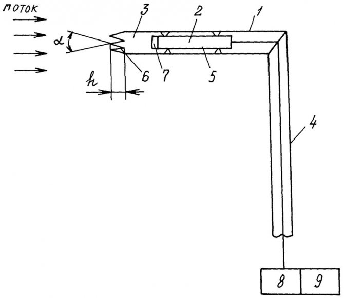
Diagram of the total pressure receiver: 1 - receiving tube, 2 - pressure transducer, 3 - braking chamber, 4 - holder, 5 - annular channel, 6 - leading edge, 7 - inlet grating, 8 - normalizer, 9 - output signal recorder, α - angle at the tops, h - depth of the valleys
If you measure a strong air flow, then the pressure should determine the speed, and then compare it with the cross-sectional size. The higher the speed per unit area and the larger the area itself, the more efficient the fan.
Full pressure at the outlet is a complex concept. The outflow stream has a non-uniform structure, which also depends on the operating mode and the type of device. The outlet air has zones of return movement, which complicates the calculation of pressure and speed.
It will not be possible to establish a regularity for the time of occurrence of such a movement. The inhomogeneity of the flow reaches 7-10 D, but the indicator can be reduced by rectifying gratings.
The Prandtl tube is an improved version of the Pitot tube: receivers are produced in 2 versions - for speeds less and more than 5 m / s
Sometimes at the outlet of the ventilation device there is a rotary elbow or a tear-off diffuser. In this case, the flow will be even more inhomogeneous.
The head is then measured according to the following method:
- The first section is selected behind the fan and scanned with a probe. At several points, the average total head and productivity are measured. The latter is then compared with the input performance.
- Further, an additional section is selected - in the nearest straight section after exiting the ventilating device. From the beginning of such a fragment, 4-6 D are measured, and if the length of the section is less, then a section is chosen at the most distant point. Then take the probe and determine the productivity and the average total head.
The calculated losses in the section after the fan are subtracted from the average total pressure at the additional section. The total outlet pressure is obtained.
Then the performance is compared at the entrance, as well as at the first and additional sections at the exit. The input indicator should be considered correct, and one of the outputs should be considered closer in value.
There may not be a straight line segment of the required length. Then choose a cross-section that divides the area to be measured into parts with a ratio of 3 to 1. Closer to the fan should be the larger of these parts. Measurements should not be made in diaphragms, dampers, outlets and other connections with air disturbance.
Pressure drops can be recorded by pressure gauges, pressure gauges in accordance with GOST 2405-88 and differential pressure gauges in accordance with GOST 18140-84 with an accuracy class of 0.5-1.0
In the case of roof fans, Pp is measured only at the inlet, and the static is determined at the outlet. The high-speed flow after the ventilation device is almost completely lost.
We also recommend reading our material on the choice of pipes for ventilation.
Basic concepts
It must be borne in mind that the pressure in the heating system implies only a parameter in which only the excess value is taken into account, without taking into account the atmospheric one. The characteristics of thermal devices take into account exactly this data. Calculated data are taken based on generally accepted rounded constants. They help to understand how the heating is measured:
| 0.1 MPa corresponds to 1 bar and is approximately equal to 1 atm |
There will be a small error when measuring at different heights above sea level, but we will neglect extreme situations.
The concept of operating pressure in a heating system includes two meanings:
- static;
- dynamic.
Static pressure is a quantity determined by the height of the water column in the system. When calculating, it is customary to assume that a ten-meter rise provides an additional 1 amt.
Dynamic pressure is injected by circulation pumps, moving the coolant along the lines. It is not solely determined by the pump parameters.
One of the important questions that arise during the design of a wiring diagram is what is the pressure in the heating system. To answer, you need to take into account the way of circulation:
- In conditions of natural circulation (without a water pump), it is enough to have a slight excess over the static value so that the coolant circulates independently through pipes and radiators.
- When a parameter is determined for systems with forced water supply, then its value must necessarily be significantly higher than the static one in order to maximize the efficiency of the system.
When calculating, it is necessary to take into account the permissible parameters of individual elements of the circuit, for example, the efficient operation of radiators under high pressure. So, cast iron sections in most cases are not able to withstand a pressure of more than 0.6 MPa (6 atm).
The launch of the heating system of a multi-storey building is not complete without installed pressure regulators on the lower floors and additional pumps that increase pressure on the upper floors.
Control and accounting methodology
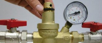
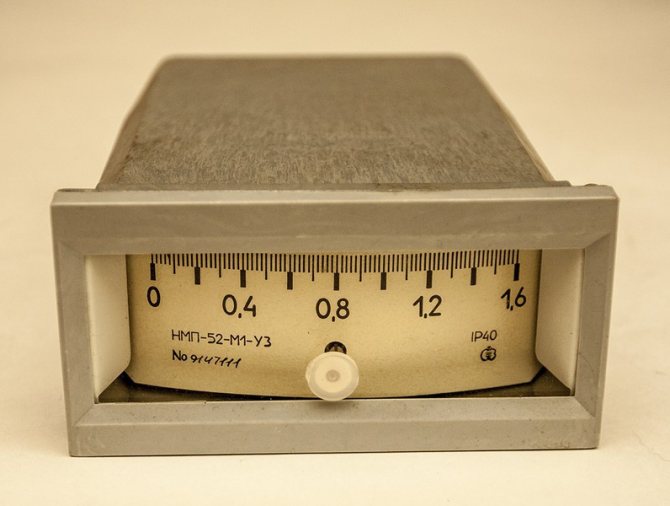
To control the pressure in the heating system of a private house or in your own apartment, it is necessary to install pressure gauges in the wiring. They will only take into account the excess of the value over the atmospheric parameter. Their work is based on the deformation principle and the Bredan tube. For measurements used in the operation of an automatic system, devices using an electrical contact type of work will be appropriate.
Pressure in the system of a private house
The insertion parameters of these sensors are regulated by the State Technical Supervision. Even if no checks are expected by the regulatory authorities, it is advisable to follow the rules and regulations in order to ensure the safe operation of the systems.
The manometer is inserted by means of three-way valves. They allow you to purge, zero or replace elements without interfering with the operation of the heating.
Decrease in pressure
If the pressure in the heating system of a multi-storey building or in the system of a private building drops, then the main reason in this situation is the possible depressurization of heating in some area. Control measurements are carried out with the circulation pumps turned off.
The problem area must be localized, and it is also necessary to identify the exact place of the leak and eliminate it.
The pressure parameter in apartment buildings is characterized by a high value, since it is necessary to work with a high water column. For a nine-story building, you need to hold about 5 atm, while in the basement the pressure gauge will show numbers in the range of 4-7 atm. On the way to such a house, the general heating main must have 12-15 atm.
It is customary to keep the operating pressure in the heating system of a private house at a level of 1.5 atm with a cold coolant, and when heated, it will rise to 1.8-2.0 atm.
When the value for forced systems falls below 0.7-0.5 atm, then the pumps are blocked for pumping. If the pressure level in the heating system of a private house reaches 3 atm, then in most boilers this will be perceived as a critical parameter at which the protection will work, bleeding off the excess coolant automatically.
Pressure rise
Such an event is less common, but you also need to prepare for it. The main reason is the problem with the circulation of the coolant. At some point, the water practically stands still.
Water volume increase table when heating
The reasons are as follows:
- there is a constant replenishment of the system, due to which an additional volume of water enters the circuit;
- the influence of the human factor happens, due to which the valves or through-flow valves were blocked in some area;
- it happens that the automatic regulator cuts off the flow of coolant from the catalytic converter, such a situation arises when the automation is trying to lower the water temperature;
- an infrequent case is the blockage of the coolant passage by an airlock; in this situation, it is enough to bleed off some of the water by removing the air through.
For reference. What is Mayevsky's crane. This is a device for venting air from radiators of central water heating, which can be opened with a special adjustable wrench, in extreme cases with a screwdriver. In everyday life, it is called a valve for bleeding air from the system.
Coping with pressure drops
The pressure in the heating system of a multi-storey building, as well as in your own house, can be maintained at a stable level without significant differences. For this, auxiliary equipment is used:
- air duct system;
- expansion tanks of open or closed type
- emergency discharge valves.
The reasons for the occurrence of pressure drops are different. Most often, its decrease is found.
VIDEO: Pressure in the expansion tank of the boiler
Features of calculating the pressure
Measuring pressure in air is complicated by its rapidly changing parameters. Manometers should be purchased electronic with the function of averaging the results obtained per unit of time. If the pressure jumps sharply (pulsates), dampers will come in handy, which smooth out the differences.
The following patterns should be remembered:
- total pressure is the sum of static and dynamic;
- the total fan head must be equal to the pressure loss in the ventilation network.
Measuring the static outlet pressure is straightforward. To do this, use a tube for static pressure: one end is inserted into the differential pressure gauge, and the other is directed into the section at the outlet of the fan. The static head is used to calculate the flow rate at the outlet of the ventilating device.
The dynamic head is also measured with a differential pressure gauge. Pitot-Prandtl tubes are connected to its connections. To one contact - a tube for full pressure, and to the other - for static. The result will be equal to the dynamic pressure.
To find out the pressure loss in the duct, the flow dynamics can be monitored: as soon as the air velocity rises, the resistance of the ventilation network rises. The pressure is lost due to this resistance.
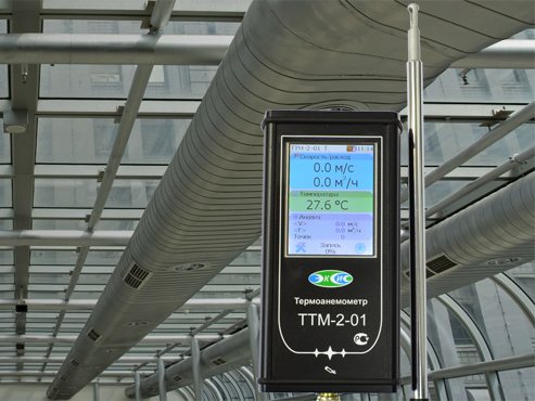
Anemometers and hot-wire anemometers measure the flow velocity in the duct at values up to 5 m / s or more, the anemometer should be selected in accordance with GOST 6376-74
With an increase in the fan speed, the static pressure drops, and the dynamic pressure increases in proportion to the square of the increase in air flow. The total pressure will not change.
With a properly selected device, the dynamic head changes in direct proportion to the square of the flow rate, and the static head changes in inverse proportion. In this case, the amount of air used and the load of the electric motor, if they grow, is insignificant.
Some requirements for the electric motor:
- low starting torque - due to the fact that the power consumption changes in accordance with the change in the number of revolutions supplied to the cube;
- large stock;
- work at maximum power for greater savings.
The fan power depends on the total head as well as the efficiency and air flow rate. The last two indicators correlate with the throughput of the ventilation system.
At the design stage, you will have to prioritize. Take into account costs, losses of useful volume of premises, noise level.
Bernoulli's equation of stationary motion
One of the most important equations of hydromechanics was obtained in 1738 by the Swiss scientist Daniel Bernoulli (1700 - 1782). He was the first to describe the motion of an ideal fluid expressed in the Bernoulli formula.
An ideal fluid is a fluid in which there are no frictional forces between the elements of an ideal fluid, as well as between an ideal fluid and the walls of a vessel.
The equation of stationary motion, which bears his name, has the form:
where P is the pressure of the fluid, ρ is its density, v is the speed of motion, g is the acceleration of gravity, h is the height at which the element of the fluid is located.
The meaning of the Bernoulli equation is that inside a system filled with liquid (a section of a pipeline), the total energy of each point is always unchanged.
The Bernoulli equation has three terms:
- ρ⋅v2 / 2 - dynamic pressure - kinetic energy per unit volume of the driving fluid;
- ρ⋅g⋅h - weight pressure - potential energy per unit volume of liquid;
- P - static pressure, by its origin is the work of pressure forces and does not represent a reserve of any special type of energy ("pressure energy").
This equation explains why in narrow pipe sections the flow velocity increases and the pressure on the pipe walls decreases. The maximum pressure in the pipes is set exactly in the place where the pipe has the largest cross section. Narrow parts of the pipe are safe in this respect, but in them the pressure can drop so much that the liquid boils, which can lead to cavitation and destruction of the pipe material.
Checking the tightness of the heating system
To ensure effective and reliable operation of the heating system, not only the pressure of the coolant is checked, but also the equipment is tested for leaks. How this happens can be seen in the photo. As a result, it is possible to control the presence of leaks and prevent equipment breakdown at the most crucial moment.
The tightness check is carried out in two stages:
- cold water test. Pipelines and batteries in a multi-storey building are filled with coolant without heating it, and pressure readings are measured. Moreover, its value during the first 30 minutes cannot be less than the standard 0.06 MPa. After 2 hours, the losses cannot be more than 0.02 MPa. In the absence of gusts, the heating system of a high-rise building will continue to function without problems;
- test using hot coolant. The heating system is tested before the start of the heating season. Water is supplied under a certain pressure, its value should be the highest for the equipment.
In order to achieve the optimal pressure value in the heating system, it is best to entrust the calculation of the scheme of its arrangement to heating specialists. Employees of such firms can not only perform the appropriate tests, but also wash all its elements.
Testing is carried out before starting the heating equipment, otherwise the cost of an error can be too expensive, and, as you know, it is quite difficult to eliminate an accident at subzero temperatures.
How comfortable you can live in each room depends on the pressure parameters in the heat supply circuit of a multi-storey building. Unlike their own home ownership with an autonomous heating system in a high-rise building, apartment owners do not have the opportunity to independently regulate the parameters of the heating structure, including the temperature and coolant supply.
But residents of multi-storey buildings, if they wish, can install such measuring devices as pressure gauges in the basement and, in the event of the slightest deviations in pressure from the norm, report this to the appropriate utilities. If, after all the actions taken, consumers are still unhappy with the temperature in the apartment, perhaps they should consider organizing alternative heating.
As a rule, the pressure in the pipelines of domestic multi-storey buildings does not exceed the limit norms, but nevertheless, the installation of an individual pressure gauge will not be superfluous.
teplospec.com
Test pressure
Residents of apartment buildings know how utilities, together with specialists from energy companies, check the pressure of the coolant in the heating system. Usually, before the beginning of the heating season, they supply a coolant to the pipes and batteries under pressure, the value of which approaches critical levels.
They use pressure when testing a heating system in order to test the performance of all elements of a heat supply structure in extreme conditions and find out how efficiently heat will be transferred from a boiler room to a multi-storey building.
When the test pressure of the heating system is applied, its elements often fall into an emergency state and require repair, since worn-out pipes begin to leak and holes form in the radiators. Timely replacement of outdated heating equipment in the apartment will help to avoid such troubles.
During the tests, the parameters are monitored using special devices installed at the lowest (usually a basement) and highest (attic) points of a high-rise building. All measurements are further analyzed by specialists. If there are deviations, it is necessary to find the problems and fix them immediately.