Why do you need a safety valve
When pumped into pipes, the coolant has a temperature of about +15 ºС, when heated in the boiler, the water begins to heat up, expand, increasing the in-pipe pressure. This can cause leaking welds, fracture or rupture of polymer fasteners. This can cause the boiler to explode. In the best case, there will be a short circuit of the boiler room electrical appliances.
If the degree of heat transfer of gas or liquid-fuel devices can still be controlled, then for solid-fuel devices it is impossible.
In the system on liquid energy carriers, the equipment is installed with sensors, built-in safety automation, which is triggered in an emergency and turns off the devices.
When heating with wood, coal, you can try to regulate the combustion force by closing the damper, but this takes time. The heat generator is inert, due to which the coolant overheats greatly.
When the oven is still in the warming up stage, it is enough to block the air supply to quickly extinguish the flame. If the combustion has heated the boiler to the maximum permissible temperature, then the combustion will slow down, and the furnace will generate a lot of heat for some time.
A safety relief valve must be used to avoid the consequences of sudden or excessive pressure build-up. At the moment of overloading the system, the shutter closes, removing part of the excess steam outside. As soon as the volume of the load returns to normal, the shutter closes, goes off in anticipation of the next reset.
Types of valves and how they work
Any modification of the safety valves in the heating system includes a shut-off element and a force action mechanism. According to the design features, several types of fuses are distinguished.
Separately classified are valves for dumping the thermal potential with a bellows, a temperature-sensitive liquid that compensates for load drops. There are models that include a safety group in the form of a blast valve with a part responsible for air discharge and a pressure gauge.
The check relief valve for the heating design can be spring-loaded or gravitational. Due to the built-in mechanisms, the contactor is kept closed, which ensures the movement of the coolant flow in one direction.
Closures are bivalve, petal, disc, pressing against the saddle, bushing, other main base. It is necessary to get a sealed shutter.
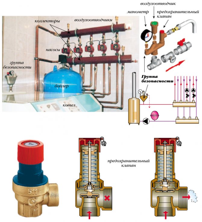
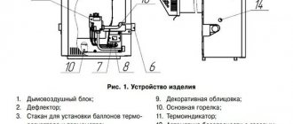
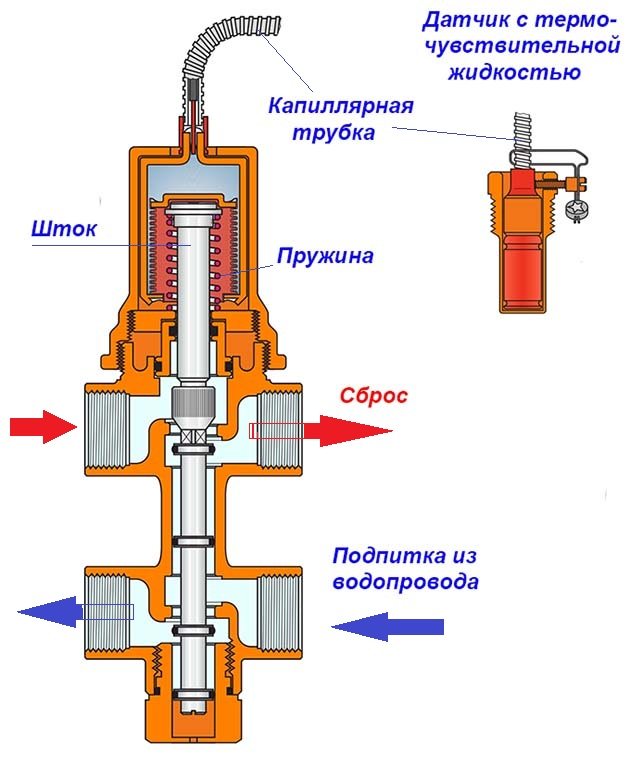
Inside view
The principle of operation of the fuse lies in the fact that in the normal state, the diaphragm layer fixed between the stem and the spring tightly adheres to the seat, hermetically closing the outlet. In the case when the coolant boils, expansion of the liquid is observed, the load inside the system rises, but is partially regulated by the expander.
At the maximum allowable load level, the spring is strongly compressed, releasing the diaphragm, which immediately opens the passage.
The lid rises to release as much hot steam as is required to stabilize the equipment.
When the work is normalized, the spring returns to its original position, the membrane tightly closes the release hole, the cap returns to its place.
If the owner is near the instruments, you can perform an emergency reset with your own hands by turning the upper handle.
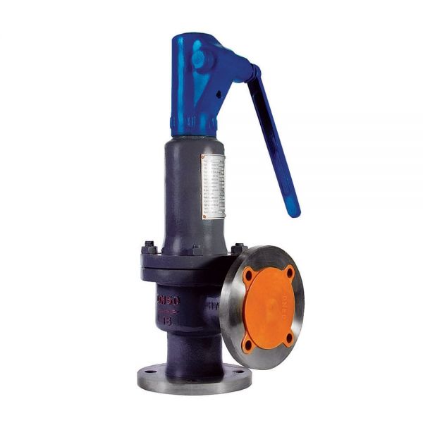
By pressing method
When heating a private house, apartment or industrial premises where low-power equipment is used, a spring-loaded valve for emergency relief of excess water pressure for the heating system is often chosen.
They are simple, compact, inexpensive but reliable models that can be combined with other equipment for safety.
The compression ratio of the spring is related to the load parameter at which the valve is actuated. The spring elasticity affects the setting range.
The principle of operation of the device: a water flow exerts pressure on the shutter, as it intensifies, the degree of compression of the spring increases greatly. From this, the spool rod rises up, releasing excess steam, and the in-line fluid volume is stabilized. In the meantime, the spring returns the unit to its original state.
Spring modifications are made of high-strength brass, hot stamping technologies are used. The spring itself is steel, and the membrane, seals, and the handle are polymer.
You can choose models with factory settings or those that need to be customized individually during installation.
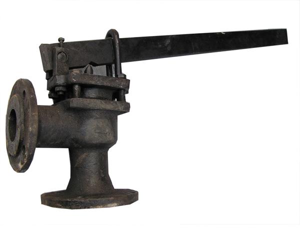
Lever fuse
Lever-weight safety devices are used less often, since the stem lifting provides an external suspended weight that moves along the entire lever, regulating the degree of pressure of the stem against the seat.
By the degree of opening the shutter
Low-lift valves assume a valve lift of no more than 0.05 times the seat diameter: the opening mechanism is fully proportional.
The product is characterized by low throughput and primitive design. The fuse is installed in installations with a liquid medium.
Full lift modification
The full lift variation contributes to the maximum allowable lift of the gate, which improves throughput as a large amount of steam is discharged at a time.
By response speed
The proportional safety valve for urgent relief of excess water pressure in the heating system assumes that the valve rises gradually, according to the degree of internal load. As the damper rises, the volume of the released steam increases smoothly. Such installations can be used with any type of boiler, but most often they are installed in systems with water or other liquid.
The on / off valves operate instantly, opening fully when the pressure rises. It is recommended to place such devices in a compressible environment. The main disadvantage of the safety element is the presence of self-oscillations of the bolt.
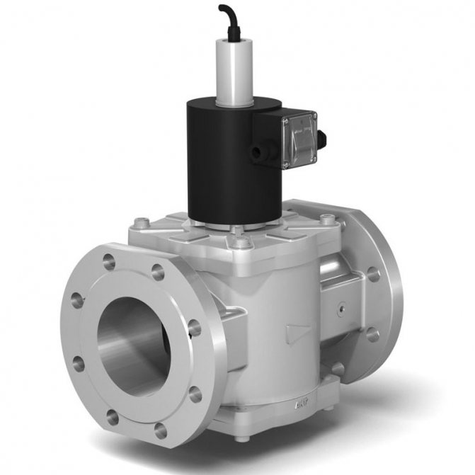
On-off valve
Installation of on-off valves should be carried out taking into account the discharge of a large amount of water with a sudden opening. It turns out a very quick release of pressure, closing the shutter, as a result - a water hammer, which is absent in proportional fuses.
You can learn more about the valve device, the principle of its operation, in the following video:
E.I. Kalinin. How to choose a safety valve? (Part 1)
First, I propose to understand: what is a safety valve, what is it for and why should it be selected at all? Maybe you should take the most beautiful one and install it?
A safety valve (definition of GOST R 52720) is a pipeline valve that protects (in fact, that is why it is a safety valve) equipment if the pressure suddenly rises there (we do not need it, high pressure). He does this by opening at the right moment (in fact, that is why he is a valve) and releasing that "unnecessary" pressure, and then he will close at the right moment (closing pressure). How does this happen? There is no magic here. The valve contains a spring which, during normal operation, (working pressure before the valve) closes the passage with its power (the spool is pressed tightly against the seat), and nothing is dumped anywhere. But if suddenly the pressure begins to rise, the spring no longer has enough strength to hold it, and the valve opens (opening pressure), the pressure is released.
Now for the selection of the valve. Safety valves come in different sizes - from very small to real giants, you can even hide in such (the nominal diameter of safety valves is from 10 to 400 mm, in the Russian Federation, the most common valves are from 25 to 200 mm). Safety valves are also divided according to the pressure at which they can be used. (nominal pressure) - after all, some have very thin walls, and the springs are very weak, while others have thick walls, and the springs are very stiff. It is not hard to guess that such a variety is not accidental and is necessary in order to meet the needs of a wide variety of facilities and industries. This is where it becomes necessary to choose the right safety valve, because if you put the "wrong", then at best we will hear a hiss (the required tightness will not be ensured), and at worst - "BOOM!" (destruction of the protected object will occur).
Now is the time to learn how to choose a safety valve. I want to warn you right away that the "watermelon principle" is not suitable here and you should not knock on the valve. And you should carefully read the questionnaire (a document containing technical and other requirements for the development and (or) supply of pipeline valves). At the same time, there is no ideal form of the questionnaire. The plant receives a wide variety of questionnaires drawn up and filled in by design institutes, end users, intermediaries and other different people. Quite often such questionnaires contain conflicting requirements and errors (unfortunately, nothing can be done about it), and it is necessary to “decipher secret messages”.
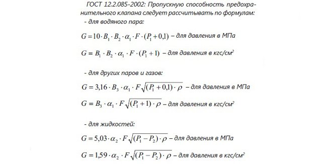
One of the main parameters that you should pay attention to in the questionnaire is the emergency flow rate of the medium, which the valve must provide when it is fully opened, GA or, as is often said, the throughput of the safety valve. This is the time to remember the "storehouse of knowledge" of any engineer, that is, regulatory and technical documentation: now we are interested in GOST 12.2.085-2002 and GOST 31294, because it is there that formulas are written by which you need to calculate - but more on that later. It is this value that directly affects which valve we need to choose.
At the same time, decent engineers use the dimension "kilogram per hour" (kg / h) (the physical meaning of this value is the mass of the working medium, which is able to exit the safety valve when it is fully opened within an hour). Here you should also carefully look at what it is about: about a liquid (water, oil and other murmuring media), about gas (here the main property is natural gas) or about water vapor (it is important not to confuse it with the national property when making calculations, because in the "storehouses of knowledge" - GOST 12.2.085-2002, GOST 31294 - different formulas are given and there is a danger of running into the "BA-BACH" option).
It is also very interesting that in the questionnaires with the working environment "natural gas", the emergency flow rate is often indicated, expressed in units of nm³ / h (pronounced as "normal cubic meter per hour"). Normal cubic meter is a special unit of measurement traditionally used for natural gas. The physical meaning of a normal cubic meter is a cubic meter of gas at a temperature of 0 ° C (273.15 K) and a pressure of 101325 Pa (0.101325 MPa = 1.03323 kgf / cm2). Also for natural gas, the unit of measurement is stm³ / h - standard cubic meter per hour. The physical meaning of a standard cubic meter is a cubic meter of gas under standard conditions specified in GOST 2939-63, that is, at a temperature of 20 ° C (293.15 K) and a pressure of 101325 Pa (0.101325 MPa = 1.03323 kgf / cm2) ...
In these cases, to calculate the mass required emergency flow, it is necessary to know the gas density under normal and, accordingly, under standard conditions.If the customer does not provide such data (and sometimes does), then it will be necessary to assume that the gas density under normal and standard conditions is approximately 0.85 kg / m³ (according to the World Wide Web, the density of natural gas under these conditions is in the "plug »0.72-0.85 kg / m³, decent engineers always take the highest density value in order to play it safe). For example, if the customer specified the required emergency flow rate of 20,000 Nm³ / h, then GA = 20,000 * 0.85 = 17,000 kg / h. Well, something like this. After this most valuable figure has been found, one should move on, and here it is time to remember the formulas.
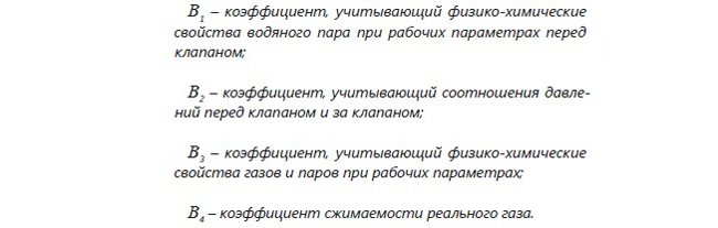
Here we need to delve into the issue and talk about values that are very important for us. It:

There is one very nice thing here: we already know these data, since they are important characteristics of valves and are given in another cult scripture (Specifications). In general, everything is quite simple further. It is necessary to calculate whether we have enough aF (we are talking about the product of these quantities) in order to provide the already known G (whether the required amount of medium can come out through the accepted cross section of the saddle). It would seem that at this point you can already finish the story, but here the most interesting and unpredictable begins, namely:
What does the "storehouse of knowledge" tell us about these wonderful accomplices of calculations?
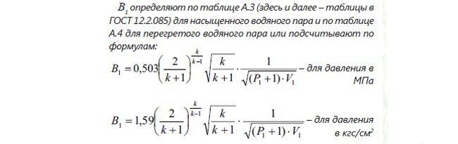
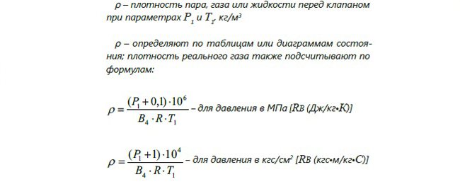
At first glance, it seems that this is a "complete paragraph", but upon closer examination it turns out that there are only a couple of unknowns (about P1 we will talk in more detail) unknowns, these are: The first, as a rule, is indicated in the questionnaires, and the second can be found in the reference book on heating engineering or calculate by the formula. And if a "decent engineer" will hammer these formulas into the same Excel, then the calculation will be very simple. Well, if the questionnaire is frankly "crooked", then at worst B1 can be taken from the tables.
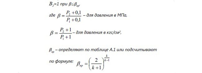
Everything is quite simple here. In my memory, there has never been a case when the condition b≤bcr was not met, so we can safely take B2 equal to 1 and sleep well. By the way, if we talk about problem-free coefficients, then
B4 - determined according to table A.2 (for ideal gas B4 = 1).
There is not even an option with formulas. Primitive.

And here in the "storehouse of knowledge" a systemic failure occurred, and, in my humble opinion, these formulas should be used like this.
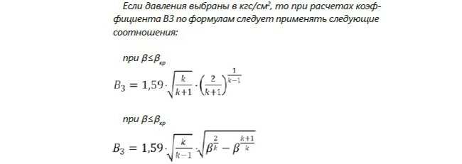
By the way, an in-depth study of non-Russian catalogs and standards confirms this judgment. Well, again, if there are doubts or the questionnaire is completely hopeless, then you can take the values from the tables. What else can you say? There are also three "assistants", without knowing which in person, the overall picture cannot be added.
There is nothing to add here, except that often the value can be seen in the questionnaire.
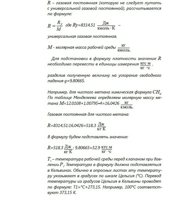
R - gas constant R is determined according to table A.1
In addition to this table, a decent engineer can also find R like this:
It's all pretty simple. There are only a couple of quantities left to discuss, these are:

What can I say here? A lot, in fact. Because pressure is what the safety valve protects against. Here you need to talk about the working pressure, and the design pressure, and what is the opening start pressure (or, as it is often called, the setting pressure), and also about the closing pressure. And most importantly, how they relate to each other.
You can find the continuation here
Published in the "Bulletin of the valve builder" No. 2 (30) 2016
Posted in the issue: "Bulletin of the valve manufacturer № 2 (30) 2016
Features of Three Way Emergency Valves
Three-way safety valves for heating construction are used in heating systems at low temperatures in the circuit.
The design provides for the presence of three holes, where one is inlet, and the other two are outgoing. Internal flows are controlled by a ball or stem valve, and fluid distribution is performed by rotations.
The valve is responsible for ensuring that all areas of the circuit are delimited, the flow density is evenly distributed over all zones, the temperature is normalized.
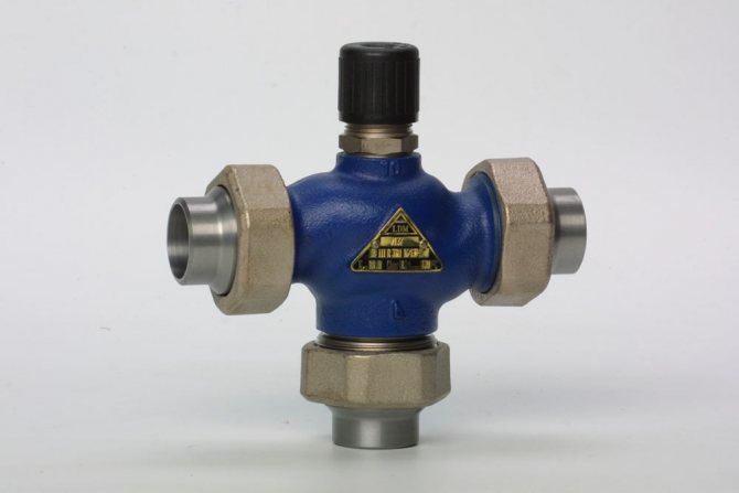
Three-way valve
If there is a floor heating system, too hot a flow should not be allowed along the floor circuit; it will need to be mixed with the cooled liquid, which provides a three-way model.
The work takes place under the control of a temperature sensor, which is placed in the low-temperature circuit. Then, in the event of deviations, a shutter mechanism is triggered, admitting or restricting the exit of liquid from the return pipes.
How the valve works in conjunction with an expansion tank
The expansion device performs regular checks, but does not protect against breakdown in emergency situations. Sometimes the tank cannot work properly because there is no air inside.
The tank is not capable of replacing the blast valve to protect the boiler or vice versa. Each of the elements has its own threshold of impact on the system, so one of them cannot be used instead of the other.
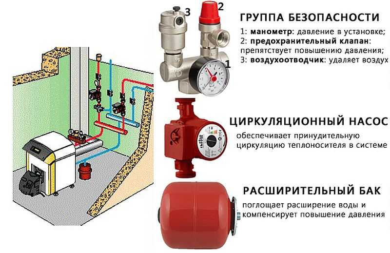
Example of equipment for a safety node
The expansion unit can temporarily accept small amounts of excess, but with a large intake of excess steam through several discharges, the tightness of the device is broken, and a constant leak appears.
The safety part is only needed for emergencies when the system is under extreme stress. After the pressure has returned to normal, it is necessary to take measures to eliminate the causes of such a jump.
Both devices protect the pipes and the boiler room in case of sudden pressure drops.
When the valve is triggered
Situations when an emergency release of pressure occurs:
- There is little coolant in the pipeline.
- Auto-fill failed.
- The absence of the expansion tank or its overlap. It also affects blood pressure a lot.
- Equipment breakdown, lack of air in its upper segment worsens the situation.
Valve functionality
When the boiler is operated at very high power, a lot of steam is produced, which is impossible to handle even with the most reliable expander.
When protection is needed
When installing equipment, it is best to immediately install an independent valve.
It is necessary to install a device on the hot water supply system if the water is heated not by the flow method, but from the heating boiler.
Separate closed circuits heated by a heat exchanger or other heat source are also fused.
The valve is needed in various hydraulic connections operating under pressure or with a compressor pump.
Calculation method
The procedure for the selection of safety valves (SPPK) is described in GOST 12.2.085-2002 - “Pressure vessels. Safety valves. Safety requirements "and
GOST 12.2.085-2017 - “Pipe fittings. Safety valves. Choice and Calculation of Throughput ". The calculation method is based on the setting pressure.
At the moment, GOST 12.2.085-82 has been replaced by GOST 12.2.085-2002.
GOST 12.2.085-2002 was replaced by GOST 12.2.085-2017, but not canceled, partially valid, applied in the EAEU.
EAEU - the Eurasian Economic Union.
Installation of the valve in the heating system
The safety valve is placed immediately behind the boiler outlet (it is enough to retreat 20-30 cm). A pressure gauge is required for visual control, monitoring the state of the system.
Do not place shut-off valves, gate valves or shut-off devices between the valve and the main heat source.

Where is the valve
To remove excess water through the outlet, install a special drain pipe connected to the sewer or return line of the pipeline.
If a closed-type gravitational system is installed, then the fuse is set at the highest point.
Requirements for inlet and outlet pipelines
7.1. Valves should be installed on branch pipes or pipelines directly connected to the vessel. When installing several valves on one branch pipe (pipeline), the cross-sectional area of the branch pipe (pipeline) must be at least 1.25 of the total cross-sectional area of the valves installed on it. When determining the cross-section of connecting pipelines with a length of more than 1000 mm, their resistance must also be taken into account. 7.2. The pressure drop before the valve in the supply line at the highest flow rate should not exceed 3% of the set pressure. 7.3. The valve piping must be provided with the necessary compensation for thermal expansion. The fastening of the valve body and piping must be sized taking into account the static loads and dynamic forces that occur when the valve is actuated. 7.4. Supply pipelines should be designed with a slope along their entire length towards the vessel. In supply pipelines, sharp changes in wall temperature (thermal shocks) should be avoided when the valves are triggered. 7.5. The inner diameter of the inlet pipeline must be at least the largest inner diameter of the valve inlet. 7.6. The internal diameter and length of the supply line should be calculated based on the largest flow capacity of the valve. 7.7. The internal diameter of the discharge line must not be less than the largest internal diameter of the valve outlet. 7.8. The inner diameter and length of the outlet pipeline must be calculated so that at a flow rate equal to the maximum throughput of the valve, the back pressure in its outlet pipe does not exceed the maximum allowable back pressure. 7.9. The connecting pipelines of the valves must be protected from freezing of the working medium in them. 7.10. The selection of the working medium from the branch pipes (and in the sections of the connecting pipelines from the vessel to the valves), on which the valves are installed, is not allowed.
Selection recommendations
Quality emergency relief valves are rarely cheap as they are made from bronze, brass or stainless steel. The main thing is to see that there is a normal value for money.
The selection of the simplest option is allowed, which costs little, but it is problematic to check it regularly.
Increases costs, but improves safety performance gauge to help monitor equipment health.
A bellows valve will help to make a small heating system autonomous.
It is important that the main mechanism is reliable enough, but not very elastic, and the adjustment is comfortable. It is necessary to immediately check the correspondence of the diameter of the fuse and the pipe emanating from the boiler, so that you do not have to change the part.
If the pipes are of small diameter, then ball or poppet equipment will be sufficient. The gravity valve is mounted only in a horizontal position, and the main shutter is always made of a petal type.
It is necessary to install several air vents if a boiler or riser is used. With a water type of heating, an expander is placed at the highest point, which replaces several air vents. But this option complicates maintenance and takes up a lot of space.
Control fittings are selected based on what degree of comfort is expected, what is the expected life of the heating. When set to the minimum setting, the noise level is reduced and in a water-heated situation, rust is prevented. The armature elements reduce the load, increase the resource values of the circulation pump.
When the coolant is oil, or the heating works well, a bypass valve is installed that works constantly, reliably providing the required level of protection.
The safety relief valve for the boiler is equipped with a special numerical marking with the letters atm, which indicates how much pressure a particular product can withstand in order to work properly.
The usual set pressure for a household fuse is 3 atm. The preload is only 1.5 atm, and the working pressure at maximum temperatures reaches 2.5 atm. This means that when the indicated parameters are exceeded, the situation becomes emergency, and the valve must be triggered.
For quality products, the minimum strength indicator is 4 atm, it is sometimes exceeded when manually pouring heating fluid.
The safety control valve stabilizes the entire system at a safe level.
The reduction model normalizes the force of the coolant inflow by adjusting the internal section of the inlet part of the pipeline.
The lever-weight variation assumes application for large pipelines with a large cross-section, includes a spool that opens the shut-off valve. The mechanism is triggered when the pressure level exceeds the weight of the weights attached to the handle.
In closed systems, a pressure valve is sometimes installed, the degree of operation of which is manually adjusted. With the help of an adjustable thermal head and mechanical action on it, it is very convenient to adjust the operation through the servo drive.
The bypass product reduces the load from the coolant, stabilizes the heating functionality. It is installed instead of a relief valve: temperature is injected in the return pipeline, after which the excess part of the liquid returns back to the common line. The pressure is now regulated.
The part is located behind the circulation pump, connected simultaneously to the supply and return pipes.
Sequence of calculation of SPPK
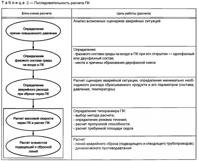
For clarity of calculation, we will start with "Calculation of the valve capacity and move on to the choice of equipment."
With the rest of the points that go above the list, you can work out on your own by picking up the specified GOSTs.
The method for calculating the throughput of the valve is specified in Appendix A (mandatory) GOST 12.2.085-2002.
Initial data for selection:
- Opening pressure 1.6 MPa;
- Working pressure 1.4 MPa;
- Serving temperature 5/20/25 ° C;
- Design temperature -52/50 ° C;
- Pressure downstream of the reducer (pressure reduction valve) -1.0 MPa;
- Wednesday - steam (water);