Calculation of the heating system make-up deaerator.
fig. 2.6. Calculation diagram of the vacuum deaerator.
opodpvd
2.10. Calculation of the HDPE system.
424dr4525dr5626dr6727dr7't
Figure 2.7. Design diagram of the HDPE system.
6t5tpsouupltdvut'prtnevozvtt7oetktoo
2.11. Determination of the steam flow rate for the turbine and verification of its power.3. Thermal calculation of HDPE and optimization of its characteristics on a computer.Initial data for IPA 4:
- consumption of heated water Gw = 0.84102 = 85.7 kg / s;
- inlet water temperature tv1 = 136 ° C;
- heating steam pressure P = 0.52 MPa;
- heating steam saturation temperature tн = 153 оС;
- temperature head of the heater t = 2 оС
- latent heat of vaporization r = 2102 kJ / kg;
- average heat capacity of water av = 4.19 kJ / kg oC;
- inner diameter of pipes dvn = 0.018 m;
- pipe thickness = 0.001m;
- thermal conductivity of brass st = 85 W / m K;
- distance between partitions H = 1 m;
- water speed c = 2 m / s;
- the price of a ton of fuel equivalent, central fuel = $ 60 / ton of fuel equivalent;
- specific cost of the heater surface kF = 220 $ / m2;
- the coefficients of the heat extraction value j + 1 = 0.4 and j = 0.267;
- the number of hours of using the installed power hsp = 6000 h;
- Boiler efficiency ka = 0.92;
- Heat flow efficiency tp = 0.98.
LtdPhysical properties of water at tвf.
322
Physical properties of the condensate film at tn.
3222ooo2ntr
4. Determination of the coefficients of the value of heat.Calculation of power change factors.The coefficients of the value of the heat of extraction are calculated by the formula:Analysis of technical solutions using CCT selections.
- Reduction of the temperature head in the HPH 6 by 1 ° C.
- Superheated steam cooler installation.
- Installation of a drainage pump on HDPE 2.
- Installing the expander.
- Increase of pressure losses in the selection pipeline to LPH 4 by 2 times.
Ltd
- Have
Installation of a drainage cooler on a high pressure pump 6.
5. Calculation of technical and economic indicators.6. Choice of auxiliary equipment of the turbine plant.
- We select feed pumps to supply feed water at the maximum power of the installation with a margin of 5%:
pnpv
- We select condensate pumps according to the maximum steam flow into the condenser with a margin:
cnc
- We select drainage pumps without a reserve (reserve - cascade drain) of the KS-32-150 type (PND 6).
- We select low pressure heaters of PN-200-16-7 I type in the amount of 4 pieces.
- High pressure heaters in the amount of three pieces, type PV-425-230-35-I.
- Deaerators are selected with a DP-500M2 type deaerator column and a BD-65-1 type deaerator tank.
Conclusion.
o2
Literature.
2
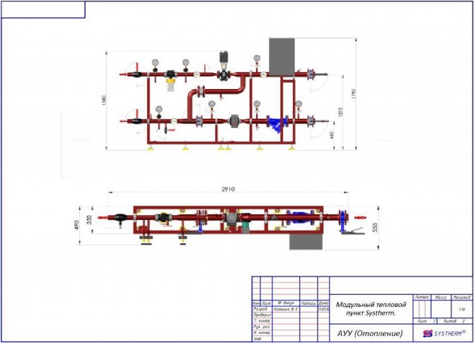
Heating module (automatic control unit AUU)
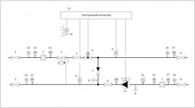
The composition of the heating module equipment
- ball valve "for welding"
- flanged strainer
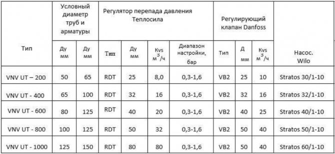
- differential pressure regulator
- control valve with electric drive
- Wafer check valve
- butterfly valve
- flanged strainer
- drainage valve
- temperature sensor
- outdoor temperature sensor
- electronic temperature controller
- circulation pump with frequency drive
- pressure switch
- bimetallic thermometer
- pressure gauge with 3-way valve
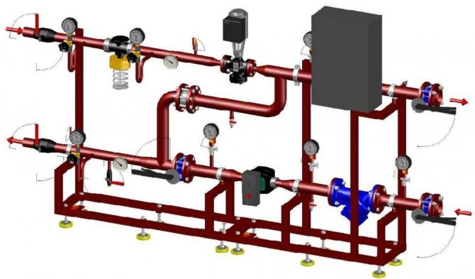
Heating block 3D model
Dimensional drawing of the heating module
Individual heating station provides the following tasks:
- Accounting for heat and coolant consumption.
- Protection of the heat supply system from an emergency increase in the parameters of the coolant.
- Shutdown of the heat consumption system.
- Uniform distribution of the heat carrier throughout the heat consumption system.
- Regulation and control of the parameters of the circulating fluid.
- Conversion of the type of coolant.
The advantages of an individual substation.
- High efficiency.
Long-term operation of an individual heating station has shown that modern equipment of this type, in contrast to other non-automated processes, consumes 30% less heat energy.
Operating costs are reduced by about 40-60%.
Selection of the optimal heat consumption mode and precise adjustment will reduce heat energy losses by up to 15%.
- Quiet work.
- Compactness.
The overall dimensions of modern heating points are directly related to the heat load. With a compact arrangement, an individual heating station with a load of up to 2 Gcal / hour occupies an area of 25-30 m2.
Possibility of placing this device in small basements (both in existing and newly constructed buildings).
- The work process is fully automated.
The maintenance of this heating equipment does not require highly qualified personnel.
ITP (individual heating station) provides comfort in the room and guarantees effective energy saving.
The ability to set the mode, focusing on the time of day, the use of the weekend and public holidays, as well as weather compensation.
- Individual production depending on the customer's requirements.
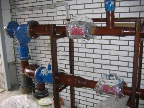
Heat metering unit.
The basis of energy-saving measures is the metering device. This accounting is required to perform calculations for the amount of consumed heat energy between the heat supply company and the subscriber. Indeed, very often the estimated consumption is much higher than the actual one due to the fact that when calculating the load, heat suppliers overestimate their values, referring to additional costs. Installation of metering devices will help to avoid such situations.
Appointment of metering devices.
- Ensuring fair financial settlements between consumers and suppliers of energy resources.
- Documenting the parameters of the heating system, such as pressure, temperature and flow rate.
- Control over the rational use of the power system.
- Control over the hydraulic and thermal operation of the heat consumption and heat supply system.
The classical scheme of metering devices.
- Thermal energy meter.
- Pressure gauge.
- Thermometer.
- Thermal converter in the return and supply pipelines.
- Primary flow transducer.
- Magnetic mesh filter.
Service.
- Connecting a reader and then taking readings.
- Analysis of errors and finding out the reasons for their occurrence.
- Checking the integrity of the seals.
- Analysis of the results.
- Verification of technological indicators, as well as comparison of thermometer readings on the supply and return pipelines.
- Topping up oil in sleeves, cleaning filters, checking grounding contacts.
- Removal of dirt and dust.
- Recommendations for the correct operation of internal heat supply networks.
Heat point diagram.
The classic ITP scheme includes the following nodes:
- Heating network input.
- Metering device.
- Ventilation system connection.
- Heating system connection.
- Hot water connection.
- Coordination of pressures between heat consumption and heat supply systems.
- Make-up of independently connected heating and ventilation systems.
When developing a project of a heat point, the mandatory nodes are:
- Metering device.
- Pressure matching.
- Heating network input.
- Completion with other units, as well as their number is selected depending on the design solution.
Consumption systems.
The standard scheme of an individual heating point can have the following systems for providing heat energy to consumers:
- Heating.
- Hot water supply.
- Heating and hot water supply.
- Heating, hot water supply and ventilation.
ITP for heating.
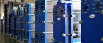
ITP (individual heating station) - independent circuit, with the installation of a plate heat exchanger, which is designed for 100% load. The installation of a double pump is provided to compensate for the loss of pressure level. Make-up of the heating system is provided from the return pipeline of heating networks.
This heat point can be additionally equipped with a hot water supply unit, a metering device, as well as other necessary blocks and assemblies.
ITP for DHW.
ITP (individual heating station) - the scheme is independent, parallel and one-stage. The complete set includes two plate-type heat exchangers, the operation of each of them is designed for 50% of the load. There is also a group of pumps designed to compensate for the decrease in pressure.
Additionally, the heating point can be equipped with a heating system block, a metering device and other necessary blocks and assemblies.
ITP for heating and hot water supply.
In this case, the work of an individual heating point (ITP) is organized according to an independent scheme. A plate heat exchanger is provided for the heating system, which is designed for 100% load. The hot water supply scheme is independent, two-stage, with two plate-type heat exchangers. In order to compensate for the decrease in the pressure level, the installation of a group of pumps is provided.
The heating system is replenished with the help of appropriate pumping equipment from the return pipe of heating networks. The hot water supply is replenished from the cold water supply system.
In addition, the ITP (individual heating station) is equipped with a metering device.
ITP for heating, hot water supply and ventilation.
The heating installation is connected according to an independent scheme. A plate heat exchanger designed for 100% load is used for the heating and ventilation system. The hot water supply scheme is independent, parallel, single-stage, with two plate heat exchangers, each designed for 50% of the load. The pressure drop is compensated by means of a group of pumps.
The heating system is replenished from the return pipe of the heating networks. Make-up of hot water supply is carried out from the cold water supply system.
Additionally, an individual heating point in an apartment building can be equipped with a metering device.
The principle of operation of the ITP.
The scheme of a heat point directly depends on the characteristics of the source supplying energy to the IHP, as well as on the characteristics of the consumers it serves. The most common for this thermal installation is a closed hot water supply system with an independent heating system connection.
An individual heating station has the following operating principle:
Through the supply pipeline, the coolant enters the ITP, gives off heat to the heaters of the heating and hot water supply system, and also enters the ventilation system.
Then the coolant is sent to the return pipeline and is fed back through the main network for reuse to the heat generating enterprise.
A certain volume of the coolant can be consumed by consumers. To replenish the losses at the heat source in CHP and boiler houses, make-up systems are provided, which use the water treatment systems of these enterprises as a heat source.
The piped water entering the heating plant flows through the pumping equipment of the cold water supply system.Then some of its volume is delivered to consumers, another is heated in the first stage hot water heater, after which it is sent to the hot water circulation circuit.
Water in the circulation loop by means of circulation pumping equipment for hot water supply moves in a circle from the heating point to consumers and back. At the same time, as necessary, consumers take water from the circuit.
In the process of circulating the liquid along the circuit, it gradually gives off its own heat. To maintain the coolant temperature at an optimal level, it is regularly heated in the second stage of the hot water supply heater.
The heating system is also a closed loop, along which the coolant moves with the help of circulation pumps from the heat point to consumers and back.
During operation, coolant leaks from the heating system circuit may occur. The replenishment of losses is handled by the ITP make-up system, which uses primary heating networks as a heat source.
Operational approval.
To prepare an individual heating station in a house for admission into operation, it is necessary to submit the following list of documents to Energonadzor:
- The current technical conditions for connection and a certificate of their fulfillment from the power supply organization.
- Project documentation with all the necessary approvals.
- The act of responsibility of the parties for the operation and separation of the balance sheet, drawn up by the consumer and representatives of the energy supplying organization.
- The act of readiness for permanent or temporary operation of the subscriber branch of the heating point.
- ITP passport with a brief description of heat supply systems.
- Help on the readiness of the heat energy metering device.
- Certificate on the conclusion of an agreement with an energy supplying organization for heat supply.
- The act of acceptance of the work performed (indicating the license number and the date of its issue) between the consumer and the installation organization.
- Order on the appointment of a person responsible for the safe operation and good condition of heating installations and heating networks.
- List of operative and operative-repair persons responsible for the maintenance of heating networks and heating installations.
- A copy of the welder's certificate.
- Certificates for used electrodes and pipelines.
- Acts for hidden works, an executive diagram of a heat point with an indication of the numbering of valves, as well as a diagram of pipelines and valves.
- Act for flushing and pressure testing of systems (heating networks, heating system and hot water supply system).
- Job descriptions, fire safety and safety instructions.
- Operating Instructions.
- Certificate of admission to operation of networks and installations.
- The register of instrumentation, the issuance of work-permits, operational, the registration of defects revealed during the inspection of installations and networks, knowledge testing, as well as briefings.
- Heat network outfit for connection.
Safety measures and operation.
The personnel serving the heat point must have the appropriate qualifications, and the responsible persons should be familiarized with the operating rules, which are stipulated in the technical documentation. This is a mandatory principle of an individual heating point approved for operation.
It is forbidden to start up the pumping equipment with the shut-off valves at the inlet closed and in the absence of water in the system.
During operation it is necessary:
- Monitor the pressure readings on the pressure gauges installed on the supply and return pipelines.
- Observe the absence of extraneous noise, and also avoid excessive vibration.
- Monitor the heating of the electric motor.
- Do not use excessive force when manually operating the valve, and do not disassemble the regulators when there is pressure in the system.
- Before starting the substation, it is necessary to flush the heat consumption system and pipelines.
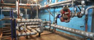
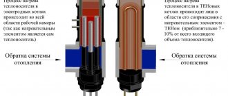
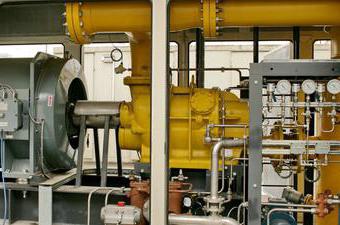
2.6. Main and auxiliary equipment of cogeneration plants
The water supplied to the heating network for the needs of consumers at the CHPP is heated in the network heaters of the turbine plants, in the peak heaters and in the peak hot water boilers, which are the main heating equipment of the CHPP. The auxiliary heating equipment includes: a heating system make-up unit, network pumps, storage tanks, recirculation pumps for hot water boilers, etc.
Peak hot water boilers (PVK) are intended for installation at CHPPs in order to cover the peaks of heating loads.
Peak hot water boilers are usually installed in separate rooms at large CHP plants or in the main building at small CHP plants. The fuel for these boilers is mostly fuel oil or gas. Due to the low use during the year, peak boilers are simple in design and inexpensive. The building can be made only for the lower part of the boilers, while the upper part of them remains in the open air. Before the CHP plant is put into operation, hot water boilers can be used for temporary district heating supply to the district. The mains water is heated sequentially in the mains heaters up to 110 ÷ 120C, and then in the PVK up to 150C maximum.
In order to avoid corrosion of the boiler metal, the temperature at the inlet to it should not be lower than 50 ÷ 60C, which is achieved by recirculation and mixing of hot and cold water. The calculated efficiency of hot water boilers for gas and fuel oil reaches 91 ÷ 93%. Coal-fired PVCLs are produced and used. They have their own dust preparation, smoke exhausters and other equipment.
Steam-water heaters of heat treatment plants
are intended for heating the heating system with steam from turbines or from boilers through reduction-cooling units (abbreviated as PRU).
Network pumps
serve to supply hot water through heating networks and, depending on the place of installation, are used as pumps of the first rise, supplying water from the return pipeline to the network heaters; the second rise to supply water after the network heaters to the heating network; recirculation, installed after peak hot water boilers.
Network pumps must have increased reliability, since interruptions or malfunctions in the operation of the pumps affect the operating mode of the CHP and consumers.
The main feature of the operation of network pumps is fluctuations in the temperature of the supplied water over a wide range, which in turn causes a change in pressure inside the pump. Network pumps must operate reliably over a wide flow range.
Typically, network pumps are centrifugal, horizontal, driven by an electric motor.
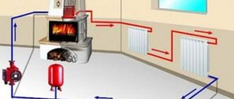
Make-up in an open heating system
In the heating networks of private houses with forced flow of the heat carrier, therefore, valves are used for recharge, supplying water to the circuit automatically. In open systems of small residential buildings or summer cottages, a slightly different, much simpler scheme for adding a coolant is usually used. In this case, the automatic feeding of the heating system will most likely be superfluous.
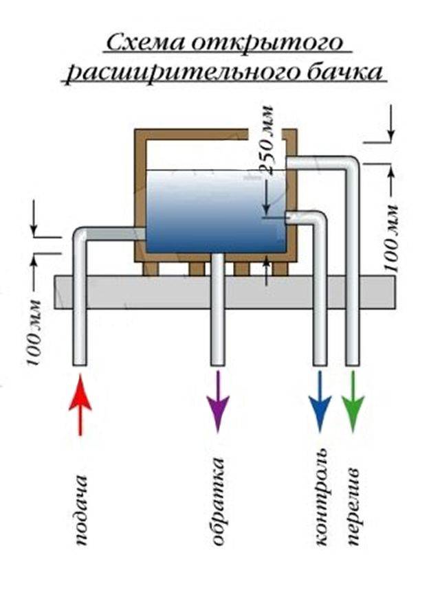
Expansion tanks in natural flow networks are usually mounted in the attic. In order to be able to control the amount of water in the circuit in such systems, in addition to the return and supply, two more pipes are supplied to them. One of them is called a control one and cuts into the tank below. The second (overflow pipe) is fed to the expansion tank at the top. Then the pipes are pulled, for example, into the kitchen.
Checking for the presence of a sufficient amount of water in the heating system circuit when using such a design is quite simple. If the coolant does not flow from the tap embedded in the control pipe of the tank when it is opened, then there is not enough of it in the system. In this case, before adding liquid to the circuit, open the valve on the overflow pipe. As soon as the system is filled to the required parameters, water will begin to flow from it.
Permit to use
To prepare an individual heating station in a house for admission into operation, it is necessary to submit the following list of documents to Energonadzor:
- The current technical conditions for connection and a certificate of their fulfillment from the power supply organization.
- Project documentation with all the necessary approvals.
- The act of responsibility of the parties for the operation and separation of the balance sheet, drawn up by the consumer and representatives of the energy supplying organization.
- The act of readiness for permanent or temporary operation of the subscriber branch of the heating point.
- ITP passport with a brief description of heat supply systems.
- Help on the readiness of the heat energy metering device.
- Certificate on the conclusion of an agreement with an energy supplying organization for heat supply.
- The act of acceptance of the work performed (indicating the license number and the date of its issue) between the consumer and the installation organization.
- Order on the appointment of a person responsible for the safe operation and good condition of heating installations and heating networks.
- List of operative and operative-repair persons responsible for the maintenance of heating networks and heating installations.
- A copy of the welder's certificate.
- Certificates for used electrodes and pipelines.
- Acts for hidden works, an executive diagram of a heat point with an indication of the numbering of valves, as well as a diagram of pipelines and valves.
- Act for flushing and pressure testing of systems (heating networks, heating system and hot water supply system).
- Job descriptions, fire safety and safety instructions.
- Operating Instructions.
- Certificate of admission to operation of networks and installations.
- The register of instrumentation, the issuance of work-permits, operational, the registration of defects revealed during the inspection of installations and networks, knowledge testing, as well as briefings.
- Heat network outfit for connection.
Benefits
- High efficiency.
- Long-term operation of an individual heating station has shown that modern equipment of this type, in contrast to other non-automated processes, consumes 30% less heat energy.
- Operating costs are reduced by about 40-60%.
- Selection of the optimal heat consumption mode and precise adjustment will reduce heat energy losses by up to 15%.
- Quiet work.
- Compactness.
- The overall dimensions of modern heating points are directly related to the heat load. With a compact arrangement, an individual heating station with a load of up to 2 Gcal / hour occupies an area of 25-30 m2.
- Possibility of placing this device in small basements (both in existing and newly constructed buildings).
- The work process is fully automated.
- The maintenance of this heating equipment does not require highly qualified personnel.
- ITP (individual heating station) provides comfort in the room and guarantees effective energy saving.
- The ability to set the mode, focusing on the time of day, the use of the weekend and public holidays, as well as weather compensation.
- Individual production depending on the customer's requirements.
Installation efficiency
An individual heating unit in an apartment building reduces the cost of heating and hot water supply:
- The heat meter itself does not affect its consumption, but it correctly takes into account.Heating companies often raise the cost of services without supplying enough heat. With accurate accounting, it turns out that before the installation of the TP, residents were overpaying.
- Automation reduces maintenance costs. More precise temperature control also reduces costs.
- A closed heat supply system is more profitable: there is no need to constantly purify water, repair pipes and radiators. Heat loss in a closed system is less.
- ITP works according to the schedule: it lowers the temperature at night, stops the pumps, and increases it in the morning.
The heat supply unit saves from 1.5 to 8 million rubles in 5 years.