Opinion of the owners of country houses about the system
According to most owners of suburban real estate, this scheme is really very effective - the Tichelman loop. This system has earned excellent reviews. A very comfortable microclimate is established in a house with its correct design and assembly. At the same time, the equipment of the system itself rarely breaks down and serves for a long time.
Not only the owners of residential buildings, but also the owners of summer cottages speak well of the Tichelman loop. The heating system in such buildings is often used irregularly during the cold season. If the wiring is done according to a dead-end scheme, when the boiler is turned on, the rooms warm up extremely unevenly. Of course, there are no such problems with a passing system. But the cost of assembling heating according to such a scheme is really more expensive than according to a dead-end one.
Cons of the scheme
- Heating according to the Tichelman scheme is not cheap pleasure, the system requires a rather long length of pipelines, so for the sake of convenience you will have to pay a certain amount. This is the most significant disadvantage;
- Laying a heating system according to this scheme causes many problems due to the interfering architectural features of the premises (doorways, for example). It is because of this moment that the Tichelman loop can be impossible to lay;
- This scheme is carried out horizontally. Laying the heating system vertically, you will have to use other schemes.
Installation procedure
The work consists of the following operations:
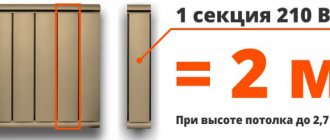
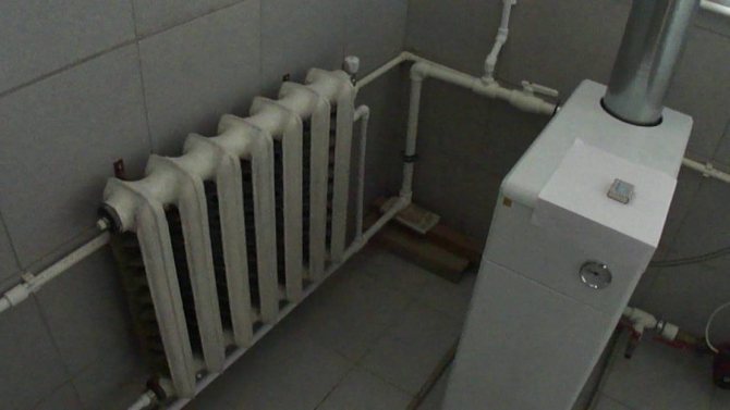
- Boiler installation. The required minimum height of the room for its placement is 2.5 m, the permissible volume of the room is 8 cubic meters. m. The required power of the equipment is determined by calculation (examples are given in special reference books). Approximately for heating 10 sq. m requires a power of 1 kW.
- Mounting of radiator sections. The use of biometric products in private homes is recommended. After selecting the required number of radiators, their location is marked (as a rule, under window openings) and fastened using special brackets.
- Pulling the line of the associated heating system. It is optimal to use metal-plastic pipes that successfully withstand high temperature conditions, which are distinguished by their durability and ease of installation. The main pipelines (supply and "return") from 20 to 26 mm and 16 mm for connecting radiators.
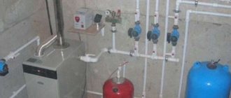
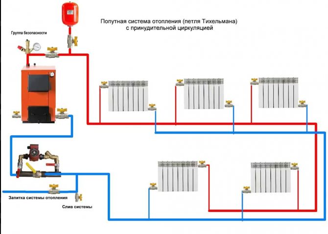
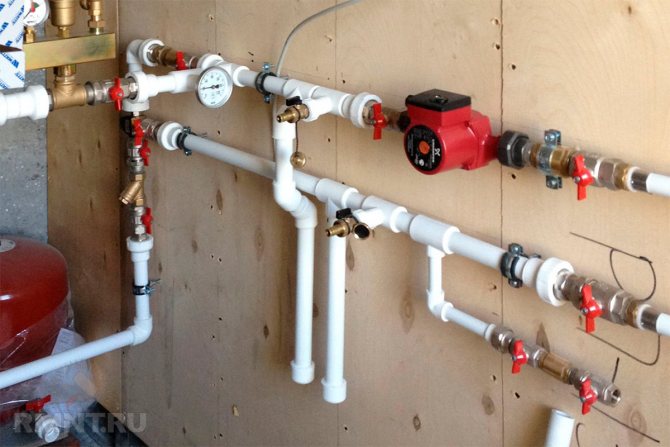
- Installation of a circulation pump. It is mounted on the return pipe near the boiler. The tie-in is carried out through a bypass with 3 taps. A special filter must be installed in front of the pump, which will significantly increase the life of the device.
- Installation of an expansion tank and elements that ensure the safety of the equipment. For a heating system with a passing flow of the heating medium, only membrane expansion tanks are selected. Elements of the safety group are supplied complete with the boiler.
To line the line of doorways in utility rooms and utility rooms, it is allowed to mount pipes directly above the door. In this place, in order to exclude the accumulation of air, automatic air vents are necessarily installed. In residential areas, pipes can be laid under a door in the floor body or bypassing an obstacle using a third pipe.
Tichelman's scheme for two-story houses provides for a certain technology. Piping is carried out with the tying of the entire building as a whole, and not each floor separately.It is recommended to install one circulation pump on each floor while maintaining equal lengths of return and supply pipelines for each radiator separately in accordance with the basic conditions of the associated two-pipe heating system. If you install one pump, which is quite acceptable, then if it fails, the heating system in the entire building will turn off.
Many experts consider it advisable to install a common riser on two floors with separate piping on each floor. This will take into account the difference in heat loss on each floor with the selection of pipe diameters and the number of required sections in radiator batteries.
A separate passing heating scheme on the floors will greatly simplify the setup of the system and will allow for optimal balancing of the heating of the entire building. But in order to obtain the desired effect, it is imperative that a tie-in into the loop of the balancing crane is required for each of the two floors. The taps can be placed side by side directly next to the boiler.

Advantages and disadvantages
The disadvantage is the need to lay pipes in a screed due to the presence of obstacles around the perimeter of the room
The advantages of installations of this type include the uniformity of heating of the entire network and the ability to adjust heat transfer by radiators. The circuit is reliable, it rarely fails, especially when compared with the operation of other systems with a large number of heating elements. This makes it a good choice for a private home.
The main drawback of the design is the limitations associated with the internal features of the arrangement of the premises. The scheme involves bypassing the perimeter of the building with a return to the boiler. In many buildings, this is not easy to organize - doors, stairwells and other obstacles do not give. Also, the installation of thick pipes implies an increase in the cost of the configuration.
Tichelmann loop for two floors or more
Most often, such a heating system is installed in large one-story buildings. It is in such houses that she works most effectively. However, sometimes such a system is assembled in two or three-story buildings. When performing wiring in such houses, you should adhere to a certain technology. According to the Tichelman scheme, in this case, not each floor is tied separately, but the entire building as a whole. That is, an equal sum of the lengths of the return and supply pipelines for each radiator of the house is kept.
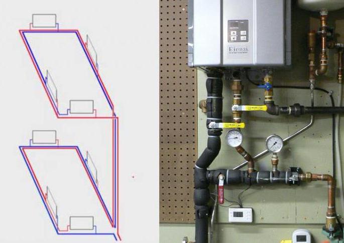
Thus, the Tichelmann loop for two floors is assembled according to a special scheme. Also, experts believe that using only one circulation pump in this case is impractical. If possible, it is worth installing one such device on each floor in the building. Otherwise, if a single pump breaks down, the heating will be turned off in the whole house at once.

Hydraulic calculation
This scheme requires the calculation of the power of the circulation pump, depending on the length of the line
An important component of the circuit is the hydraulic pump, which creates supply pressure and vacuum on the return path. These calculations demonstrate that the values of both parameters decrease as the distance from the pump increases in the direction of movement of the coolant. If you measure the data on a 100-meter pipe, it turns out that at a distance of 10 m, the supply pressure will be 90% of the nominal, and the reverse vacuum will be 5%. With a range of 20 m, these parameters will be 75% and 20%, respectively, and the drop on the radiator element in both cases will be 95%. At a distance of 50-60 m, the numbers shift to the middle (45 and 40, 40 and 45, respectively), and the drop on the radiator is 85%. With further distance from the pump, the proportions continue to change in the direction of increasing vacuum; pressure reduction at a distance of 70 m will be 90%, and at a distance of 80 m and more - 95%. Thus, in the middle part, the head losses will be slightly higher than at the beginning and end.Proportionally varying indicators allow maintaining approximately equal pressure drops of the radiators.
With correct installation, no differences in the cross-section of the main pipe and the same height of the radiators, the system functions smoothly. The capacities of the batteries involved will be equal to each other.
Areas of application of the Tichelman hinge
The increased consumption of materials is not always better, therefore, the Tichelman system in a two-story house is rarely used. An exception is the highway with the placement of radiators around the perimeter of the building. The ring system will require significant costs for materials, but the arrangement of the closed ring is carried out only in the absence of interference in the form of doorways, windows "to the floor". We'll have to lay another line to return the coolant to the heating device.
If the loop is lengthened, moved away from the heater, the pipe cross-section is increased, or a powerful circulation pump is selected, otherwise the system will not be able to work at full capacity.
To reduce the flow rate of the coolant in the area where the first batteries are connected, the diameter of the pipeline should be reduced, this will help maintain the water pressure in subsequent sections. Reducing the diameter is carried out only according to preliminary calculations, otherwise radiators located at a considerable distance from the heating device will not receive the coolant in sufficient volume.
It turns out that it is possible to use two-pipe wiring with a passing water flow only with a total length of the line of 70 meters, on which it is installed from 10 radiators. Otherwise, the associated wiring will not justify the investment.

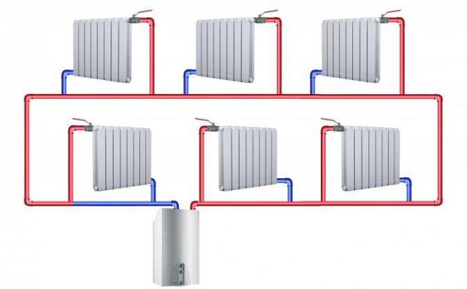
Disadvantages of a dead-end two-pipe heating system
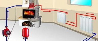
In a dead-end heating system, the coolant enters the heating device, then into the return pipeline, through which it moves to the boiler. The closer the radiator is to the boiler, the more intense the heat transfer process in it. And vice versa, the farther the heating device is from the boiler, the longer is the path of the coolant to it and the less is the supply of its thermal energy. As a result, it is hot in a room located closer to the boiler, while in remote rooms, on the contrary, it is cool.
In order to eliminate such "distortions" in the heating system, its balancing is used, with the help of valves and pipes of various diameters, changing the flow rate of the coolant separately for each heating device.
In turn, the shut-off valves create additional resistance in the heating system, to overcome which it is necessary to install a more powerful circulation pump. At the same time, the installation of a circulation pump that is too powerful can cause hydraulic noise in the heating system, which can lead to undesirable consequences in its operation.
Another disadvantage of a dead-end heating system is the balancing process itself. When performing it in manual mode, it can be very difficult to get the desired result and evenly provide heat to the whole house, and controlling the heating of heating devices in automatic mode can be expensive.
The Tichelman heating system is devoid of all of these shortcomings.
What is Tichelman's loop
Tichelman's loop (also called a "passing scheme") is a piping diagram of a heating system. Such a scheme combines the advantages of two common schemes at the same time: the Leningrad and two-pipe, while having additional advantages.
When compared with a two-pipe scheme, then when using the Tichelman loop, there is no need to install expensive control systems. The heaters work like one large radiator. The coolant flow is the same throughout the heating circuit. There are no pipe constrictions and dead-end radiators, in which the duct is worst of all.The disadvantage in comparison with a two-pipe heating scheme is that the entire branch must be made with a large diameter pipe, which can greatly affect the cost of the entire system as a whole.
If we compare it with the Leningrad (one-pipe) scheme, the advantage is that the coolant does not pass through the pipe past the radiator. The Leningrad circuit is very demanding on the circuit design and installation. With a low qualification of performing either the first or the second, it will be impossible to force the water to pass through the heater, it will pass through the pipe by. The radiator will remain slightly warm. In addition, in the Leningrad scheme, the first radiators in terms of water flow will be hotter than the subsequent ones. Since the water reaches them already chilled. The disadvantage of the Tichelman loop in comparison with the "Leningrad" loop is that the pipe consumption is almost doubled.
Of the general advantages, I would like to note that such a scheme is difficult to unbalance. The conditions for the movement of the coolant are almost ideal, which, moreover, is positively reflected in the operation of the heat generator (be it a boiler, solar systems or something else).
The main disadvantage of the associated heating scheme is certain requirements for the room. In practice, it is not always possible to organize the circular movement of the coolant. Doorways, architectural features, etc. may interfere. In addition, it can be used only with horizontal wiring; with a vertical Tichelman loop, it is not applicable.
The diameters in the Tichelman loop are selected in the same way as in a two-pipe dead-end heating system. Where the flow rate is greater, there is also a larger diameter. The farther from the boiler, the lower the flow rate can be.
If you choose the wrong diameters, then the average radiators will not heat well.
More about the program
If an artificial hydraulic resistance to the radiator branches is not created in the pressure heating system, then medium radiators will not heat well either.
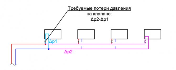
What conditions must be observed in the Tichelman loop in order for medium-sized radiators to heat well?
Each radiator branch must have a hydraulic resistance equal to 0.5-1 Kvs. This resistance can be given by a thermostatic or balancing valve, which is placed on the radiator line. As a rule, when savings are made on thermostatic and balancing valves (that is, they are not installed), then each radiator branch begins to have a low hydraulic resistance, which is comparable to if you simply connected the supply and return with a pipe (Roughly made a bypass).
Note:
For gravitational heating systems with natural circulation, the radiator branches do not need to create artificial resistance. Because due to the natural pressure of the coolant, the radiator branch itself affects its consumption.
The Tichelmann loop can be used without a pump, but only with large diameters, as is done for gravitational heating systems with natural circulation. And to calculate the diameters, the heating system simulator program will help you: More about the program
How to choose the diameters in the Tichelman loop?
The diameters in the Tichelman loop are not an easy task, as is the choice of diameters in a two-pipe dead-end heating system. The principle of choosing the diameters depends on the flow rates and head losses in the pipeline.
Below you will see how the diameters are selected.
Bad Tichelmann loop chains
Medium radiators will work poorly if there is no artificial hydraulic resistance on the radiator branches. Artificial resistance is created by balancing or thermostatic valves. For which the throughput is 0.5 - 1.1 Kvs.
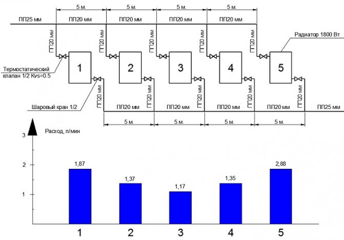
Pressure heating system with ball valves and 20 mm polypropylene pipe.
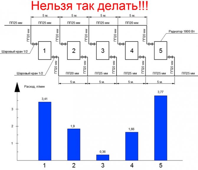
You cannot do this on ball valves:
Such a radiator branch has a low hydraulic resistance. She will eat a lot of consumption and other radiators will have little.
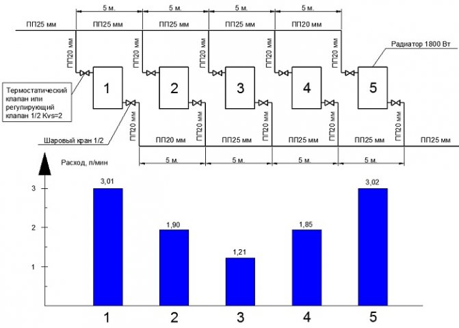
A chain for 5 radiators with a 25mm PP main pipe was tested.
Radiator costs are not the same. The third radiator has the smallest flow rate. This is due to the fact that there are ball valves on the radiator branches.
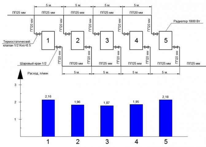
If thermostatic valves are added to the circuit, then the costs become more equally divided:
The picture is already better! But the diameters can be reduced in some places and save on this. For example, on the supply line up to 4 radiators and on the return line from 2 radiators.
If we try to leave PP20mm on the entire highway, we will get the following costs.
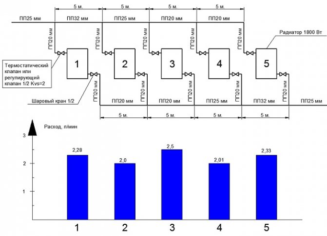
If we were to use a thermal valve or any regulating device for 2 Kvs, then the change in diameters would have to be done!
Because if someone turns on the tap completely, it will prevent other radiators from working properly. There are 5 Kvs control valves for radiators. Well, if you wake up to twist the lower valve to reduce the throughput, then do this adjustment. Of course, it will be better to use closed balancing valves, which will not be accessible to unauthorized people.
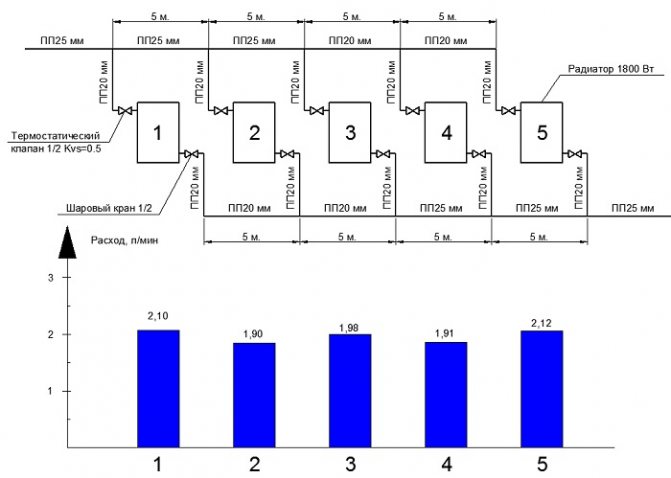
In order to improve the separation of costs for 5 radiators with the use of control valves with a larger flow capacity, it is necessary to use pipes PP32, PP25 and PP20.
Nice Tichelmann loop chains
Diameter selection criteria:
The choice of diameters for the Tichelman loop was chosen based on the chain drop of a maximum of 1 m.w. The temperature difference of the radiators is 20 degrees. The inlet temperature is 90 degrees. The difference in the output power between the radiators does not exceed 200 W. The difference in temperature differences between the radiators does not exceed 5 degrees.
Note:
The diameters indicated do not apply to low temperature heating systems. For low-temperature systems, it is necessary to reduce the temperature difference to 10 degrees and this requires a twofold increase in flow.
I prepared chains of Tichelman loops for 5 and 7 radiators for metal-plastic and polypropylene pipes.
5 radiators polypropylene pipe, Kvs = 0.5.
5 radiators, metal-plastic pipe, Kvs = 0.5.
7 radiators polypropylene pipe, Kvs = 0.5.
This chain uses PP32 mm. If you put the balancing valve on the radiator 1 and 7, then you can change the pipe from PP32 to PP26 mm. It is necessary to tighten the balancing valves on radiators 1 and 7.
7 radiators, metal-plastic pipe, Kvs = 0.5.
The diameter selection tests were carried out in the heating simulator program.
More about the simulator program
The program is used to test heating systems before being installed on site. It is also possible to test existing heating systems to improve the performance of an existing heating system.
If you need calculations of diameters for your heating system for 10 radiators, then apply for calculation services here: Order a calculation service
Calculation of the Tichelmann loop
As in a two-pipe dead-end heating system, diameters also have to be selected based on the flow rate and head loss of the coolant. The Tichelmann loop is a complex chain and the mathematical calculation becomes much more complicated.
If in a two-pipe dead-end the chain equation looks simpler, then for the Tichelman loop the chain equation looks like this:
More information about this calculation is described in the video course on the calculation of heating here: Video course on the calculation of heating
How to set up a Tichelman loop? How to set up a passing heating system?
As a rule, the Tichelman loop has conditions when average radiators do not heat well, in this case, as in a dead-end duct pipe, we clamp the balancing valves on the radiators located closer to the boiler. The closer the radiators are to the boiler, the tighter we squeeze.
| Like |
| Share this |
| Comments (1) (+) [Read / Add] |
A series of video tutorials on a private house
Part 1. Where to drill a well? Part 2. Arrangement of a well for water Part 3. Laying a pipeline from a well to a house Part 4.Automatic water supply
Water supply
Private house water supply. Principle of operation. Connection diagram Self-priming surface pumps. Principle of operation. Connection diagram Calculation of a self-priming pump Calculation of diameters from a central water supply Pumping station of water supply How to choose a pump for a well? Setting the pressure switch Pressure switch electrical circuit Principle of operation of the accumulator Sewerage slope for 1 meter SNIP Connecting a heated towel rail
Heating schemes
Hydraulic calculation of a two-pipe heating system Hydraulic calculation of a two-pipe associated heating system Tichelman loop Hydraulic calculation of a single-pipe heating system Hydraulic calculation of a radial distribution of a heating system Diagram with a heat pump and a solid fuel boiler - logic of operation Three-way valve from valtec + thermal head with a remote sensor Why does the heating radiator in a multi-apartment building do not heat well? home How to connect a boiler to a boiler? Connection options and diagrams DHW recirculation. Principle of operation and calculation You do not correctly calculate the hydraulic arrow and collectors Manual hydraulic calculation of heating Calculation of a warm water floor and mixing units Three-way valve with a servo drive for DHW Calculations of DHW, BKN. We find the volume, power of the snake, warm-up time, etc.
Water supply and heating constructor
Bernoulli's equation Calculation of water supply for apartment buildings
Automation
How servos and three-way valves work Three-way valve to redirect the flow of the heating medium
Heating
Calculation of the heat output of heating radiators Radiator section Overgrowth and deposits in pipes worsen the operation of the water supply and heating system New pumps work differently ... connect an expansion tank in the heating system? Boiler resistance Tichelman loop pipe diameter How to choose a pipe diameter for heating Heat transfer of a pipe Gravitational heating from a polypropylene pipe
Heat regulators
Room thermostat - how it works
Mixing unit
What is a mixing unit? Types of mixing units for heating
System characteristics and parameters
Local hydraulic resistance. What is CCM? Throughput Kvs. What it is? Boiling water under pressure - what will happen? What is hysteresis in temperatures and pressures? What is infiltration? What are DN, DN and PN? Plumbers and engineers need to know these parameters! Hydraulic meanings, concepts and calculation of heating systems circuits Flow coefficient in a one-pipe heating system
Video
Heating Automatic temperature control Simple top-up of the heating system Heating technology. Walling. Underfloor heating Combimix pump and mixing unit Why choose underfloor heating? Water heat-insulated floor VALTEC. Video seminar Pipe for underfloor heating - what to choose? Warm water floor - theory, advantages and disadvantages Laying a warm water floor - theory and rules Warm floors in a wooden house. Dry warm floor. Warm Water Floor Pie - Theory and Calculation News to Plumbers and Plumbing Engineers Are you still doing the hack? First results of the development of a new program with realistic three-dimensional graphics Thermal calculation program. The second result of the development of Teplo-Raschet 3D Program for thermal calculation of a house through enclosing structures Results of the development of a new program for hydraulic calculation Primary secondary rings of the heating system One pump for radiators and underfloor heating Calculation of heat loss at home - orientation of the wall?
Regulations
Regulatory requirements for the design of boiler rooms Abbreviated designations
Terms and Definitions
Basement, basement, floor Boiler rooms
Documentary water supply
Sources of water supply Physical properties of natural water Chemical composition of natural water Bacterial water pollution Requirements for water quality
Collection of questions
Is it possible to place a gas boiler room in the basement of a residential building? Is it possible to attach a boiler room to a residential building? Is it possible to place a gas boiler room on the roof of a residential building? How are boiler rooms divided according to their location?
Personal experiences of hydraulics and heat engineering
Introduction and acquaintance. Part 1 Hydraulic resistance of the thermostatic valve Hydraulic resistance of the filter flask
Video course Calculation programs
Technotronic8 - Hydraulic and thermal calculation software Auto-Snab 3D - Hydraulic calculation in 3D space
Useful materials Useful literature
Hydrostatics and hydrodynamics
Hydraulic Calculation Tasks
Head loss in a straight pipe section How does head loss affect the flow rate?
miscellanea
Do-it-yourself water supply of a private house Autonomous water supply Autonomous water supply scheme Automatic water supply scheme Private house water supply scheme
Privacy Policy
Traditionally used heating schemes
- One-pipe. The circulation of the heat carrier is carried out through one pipe without the use of pumps. On the line, the radiator batteries are connected in series, from the very last through the pipe the cooled medium is returned to the boiler (“return”). The system is simple to implement and economical due to the need for fewer pipes. But the parallel movement of streams leads to a gradual cooling of the water, as a result, to the radiators located at the end of the series chain, the carrier arrives significantly cooled. This effect increases with an increase in the number of radiator sections. Therefore, in rooms located near the boiler, it will be excessively hot, and in remote rooms, it will be cold. To increase heat transfer, the number of sections in the batteries is increased, different pipe diameters are installed, additional control valves are installed, and each radiator is equipped with bypasses.
- Two-pipe. Each radiator battery is connected in parallel to the pipes for the direct supply of the hot coolant and the “return”. That is, each device is supplied with an individual outlet to the "return". With the simultaneous discharge of cooled water into the common circuit, the coolant returns to the boiler for heating. But at the same time, the heating of heating devices also gradually decreases as they move away from sources of heat supply. The radiator located first in the network receives the hottest water and is the first to give the carrier to the “return”, and the one located at the end receives the coolant as the last one with a lowered heating temperature and also the last to give water to the return circuit. In practice, in the first appliance, the hot water circulation is the best, and in the last one it is the worst. It is worth noting the increased price of such systems in comparison with one-pipe systems.
Both schemes are justified for small areas, but ineffective with long networks.
An improved two-pipe heating scheme is Tichelman. When choosing a specific system, the determining factor is the availability of financial capabilities and the ability to provide the heating system with equipment that has the optimal required characteristics.
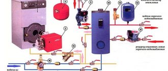
System installation process
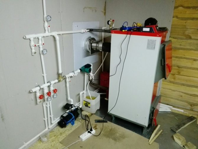
Work on the installation of Tichelman's heating begins with the installation of a boiler, which is supposed to be placed in a room of at least 250 cm. The power of the device depends on the heated area: 1000 W is required for 10 m2 of area.
After that, you need to do the following:
- Hang up the radiator sections.Having determined the required number of elements, mark their future localization - they are usually placed under the windows. Reinforce the radiators with brackets.
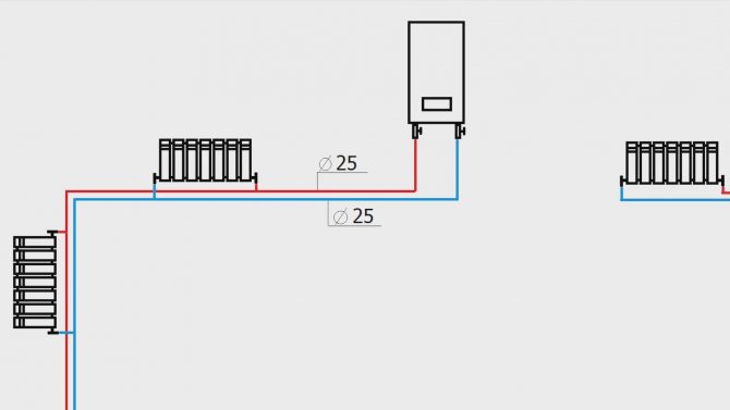
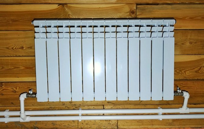
- Stretch pipes made of metal-plastic, through which the supply and return will go. This material is recommended for its ease of installation and high temperature resistance. Diameters should be 20-25 mm (for main pipes) and 16 mm (battery connection).
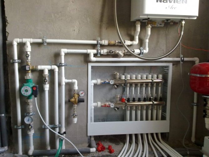
- Install the circulation pump on the return line next to the boiler. A filtration device must be placed in front of it. They cut the pump through a bypass with three taps.
- Install the expansion tank and safety parts responsible for the safety of the system.
The simplest and most inexpensive method of water preparation is the use of an indirect boiler in the Tichelman loop. Automated boilers are usually easy to connect to and control the heating device. Otherwise, to turn on the boiler, you will need to create a piping.
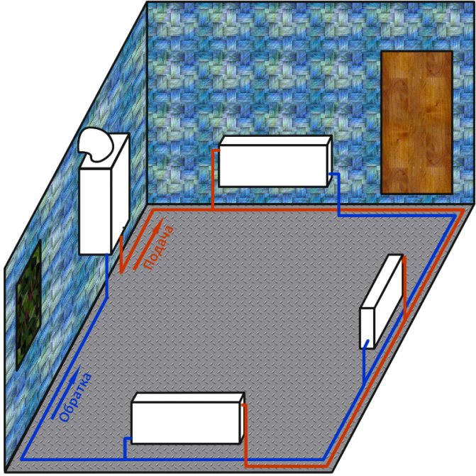
In ancillary and outbuildings, it is considered permissible to place a bypass pipeline directly above the doors. In this case, an air exhaust device must be placed at the highest point of the configuration, and a drainage mechanism must be installed at the bottom.
Tichelman heating feature
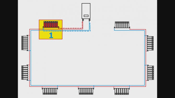
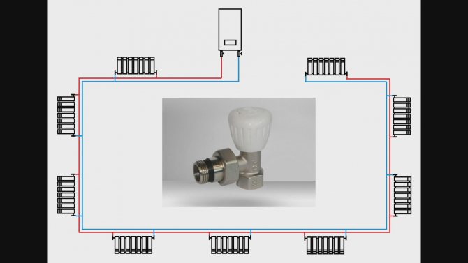
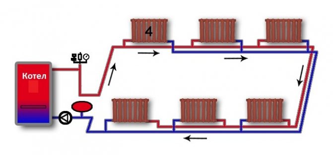
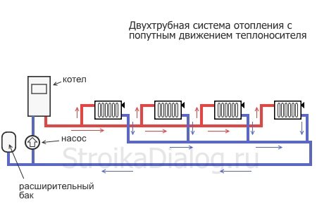
The idea of changing the principle of operation of the "return" was substantiated in 1901 by the German engineer Albert Tichelman, in whose honor it got its name - "Tichelman loop". The second name is “reversible type return system”. Since the movement of the coolant in both circuits, supply and return, is carried out in the same, concurrent direction, the third name is often used - “scheme with concomitant movement of thermal carriers”.
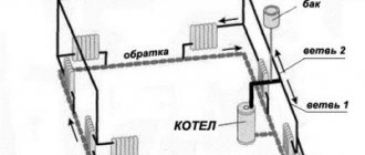
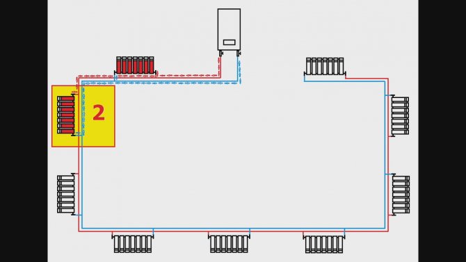
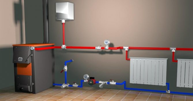
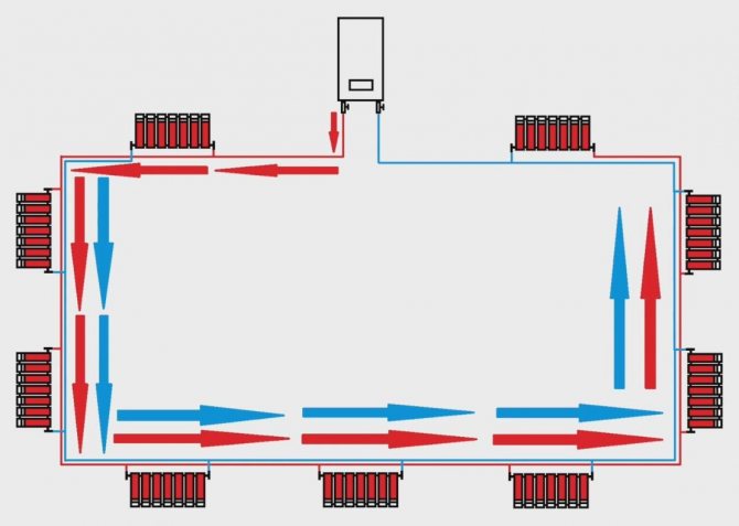
The essence of the idea consists in the presence of the same length of straight and return pipe sections connecting all radiator batteries with a boiler and a pump, which creates the same hydraulic conditions in all heating devices. Circulation loops of equal length create conditions for the hot coolant to pass the same path to the first and last radiators with the same thermal energy being received by them.
Tichelman loop diagram:
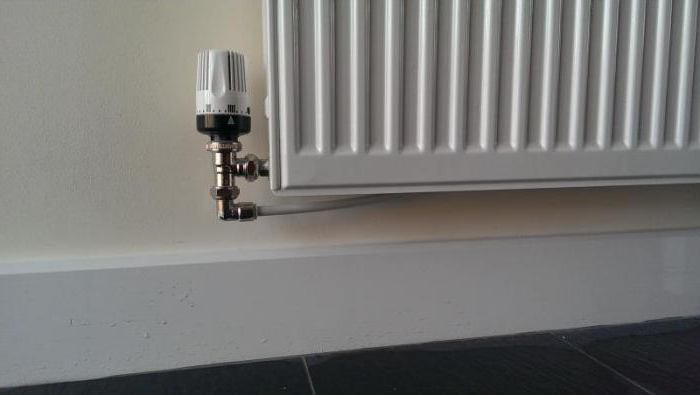
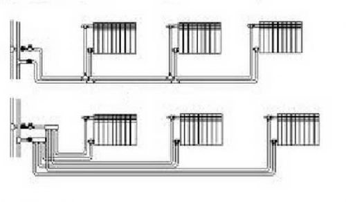
Horizontal and vertical riser?
The horizontal system involves connecting radiators to a single riser, which is best located outside residential premises: in the corridor or on the staircase. The main advantage of this option is saving pipes and lower installation costs. The disadvantages include some difficulties in operation and a tendency to education in the system. To bleed them, Mayevsky taps are usually installed on radiators. A horizontal structure is used most often in one-story buildings of a large area.
The horizontal arrangement of the system saves on pipes and installation. However, such a system has a tendency to airing, which requires the installation of additional equipment, for example, Mayevsky cranes
When arranging a vertical system, all heating devices are supplied to the vertical riser. This method allows you to connect separately each floor of a multi-storey building. The main advantage is that no air locks are formed during operation. However, the arrangement of the vertical version of the system will cost a little more than the horizontal one.
The vertical design is not prone to the appearance of air jams during operation, but it is more expensive to equip
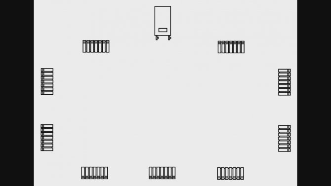
Brief description of the "ride"
It must be said right away that from a purely structural point of view, a "ride" is perhaps the simplest among the options offered in the modern construction industry. The associated heating system involves drawing the supply pipe in the traditional way, that is, laying it directly from the boiler into the last radiator according to the scheme.At the same time, there is a return pipe, the installation of which is carried out as follows: it extends to the heating device from the very first radiator. Due to the specifics of laying this type of wiring, the total length of the pipes that are connected to each battery is the same. In simple words: if a short supply pipe leads to the battery, then the branch pipe will be long enough.
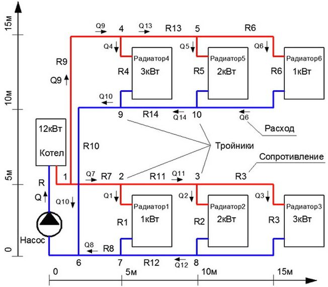
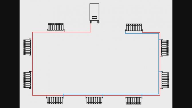
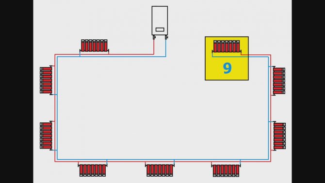
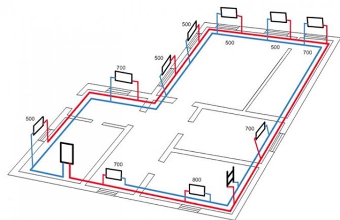
System diagram showing capacities
Is it worth it to mount it yourself
As it was already possible to understand from all of the above, the heating "Tichelman's Loop" has a rather simple design. In any case, assembling it will not be more difficult than a conventional dead-end system. However, it should be borne in mind that the Tichelman loop is most often mounted in houses of a very large area. The assembly of heating systems in such buildings already in itself has a lot of nuances. In addition, the calculation of communications for such an object should be made as accurate as possible. Simply taking the average values (10 kW of the boiler per 1 m2 of the room, pipe diameters 26 and 16) in this case will not work. It will be quite difficult to make the correct calculations using tables and even using the appropriate programs on your own. Therefore, it is still worth hiring specialists to design and install the Tichelman Loop system in a large house.
How to calculate the required pipe diameter?
Naturally, in the process of designing a heating system scheme in a specific architectural object, it is necessary to determine what the diameter of the pipes in the structure should be. In this case, it is assumed to calculate the general heat-power indicators. This must be done first of all, since otherwise the installation of heating will be difficult. So, in the process of determining the diameter of the pipes, we calculate the power of the structure. It is necessary to determine the following parameters in advance:
- the volume of the house;
- the difference in temperatures inside the premises and in the environment;
- the standard coefficient for heat loss, which in turn directly depends on how insulated the architectural volume as a whole is.
Two-pipe system diagram
In relation to the coefficient, there are already predetermined numbers that depend on the degree of thermal insulation of the architectural object. So, if there is a minimum thermal insulation or it is completely absent, then the coefficient is 3 or 4. In the case of facing a building with bricks, this indicator varies in the range from 2 to 2.9. Given the average level of heat insulation in the premises, a coefficient with a value of about 1.8 is proposed. In conclusion, it should be said that if the house is insulated with high-quality building materials, and also provided that the installation of double-glazed windows and modern doors at all entrances to the building has been carried out, the heat loss coefficient is minimal - no more than 0.9.
After the calculations described above, it is necessary to determine at what speed the coolant will move through the pipes. The traditional range of values for this parameter is from 0.36 to 0.7 meters per second. Experts call this framework optimal. As a rule, a pipe diameter in the region of 26 millimeters is most suitable for both the return line and the supply. To connect radiators to the system, experts recommend using 16-mm pipes.
Algorithm of work
In order to carry out a high-quality installation of the system in your own home, you will have to follow a certain technology. So, the assembly is carried out in the following order:
- boiler installation;
- installation of radiators;
- laying of highways;
- installation of a circulation pump;
- installation of an expansion tank, as well as objects of the security group.
During the installation of the system, do not forget that it is necessary to take into account the specifics of the layout of each specific room. It should be taken into account how the main routes, which in one way or another still need to be laid near the door, spoil the visual image of the rooms. In utility rooms, it makes no sense to hide pipes, but in living rooms, the pipe can be extended directly under the door.
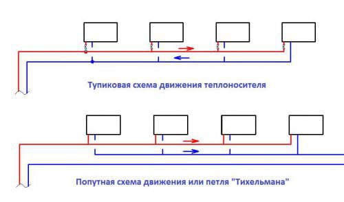
Dead-end and passing scheme of the coolant movement
Factors of the appropriateness of the choice
Modern heating systems are represented both in the domestic and in the world market of the construction industry in a wide variety. However, each of the proposed design solutions is advisable to apply in some specific cases. If we consider specifically the Tichelmann loop system, its installation is a rational solution if:
- you have a large house, the organization of heating in which involves the installation of a large number of batteries;
- there is a possibility of laying pipes exclusively around the perimeter of the rooms;
- you are ready to spend a relatively large amount of finance on the organization of heating in the house.
The above is the traditional minimum list of conditions, according to which the choice in favor of a "ride" is rational and reasonable. Thus, if the operation of the circular pump is determined by the influence of balancing, and there is no need to lay a three-pipe system with large loops, it is the associated circuit that will function optimally in your home.
Valve setting - scheme with dead-end movement of the coolant