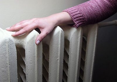
Heating water speed rate
Diameter of pipelines, flow velocity and coolant flow rate.
This material is intended to understand what the diameter, flow rate and flow rate are. And what are the connections between them. In other materials, there will be a detailed calculation of the diameter for heating.
In order to calculate the diameter, you need to know:
| 1. The flow rate of the coolant (water) in the pipe. 2. Resistance to the movement of the coolant (water) in a pipe of a certain length. |
Here are the necessary formulas to know:
| S-Sectional area m 2 of the internal lumen of the pipe π-3,14-constant - the ratio of the circumference to its diameter. r-Radius of a circle equal to half the diameter, m Q-water flow rate m 3 / s D-Internal pipe diameter, m V-coolant flow velocity, m / s |
Resistance to the movement of the coolant.
Any coolant moving inside the pipe strives to stop its movement. The force that is applied to stop the movement of the coolant is the resistance force.
This resistance is called pressure loss. That is, the moving heat carrier through a pipe of a certain length loses pressure.
The head is measured in meters or in pressures (Pa). For convenience, it is necessary to use meters in the calculations.
In order to better understand the meaning of this material, I recommend following the solution of the problem.
In a pipe with an inner diameter of 12 mm, water flows at a speed of 1 m / s. Find the expense.
Decision:
You must use the above formulas:
| 1. Find the cross section 2. Find the flow |
| D = 12mm = 0.012 m p = 3.14 |
S = 3.14 • 0.012 2/4 = 0.000113 m 2
Q = 0.000113 • 1 = 0.000113 m 3 / s = 0.4 m 3 / h.
There is a pump with a constant flow rate of 40 liters per minute. A 1 meter pipe is connected to the pump. Find the inner diameter of the pipe at a water speed of 6 m / s.
Q = 40l / min = 0.000666666 m 3 / s
From the above formulas I got the following formula.
Each pump has the following flow-resistance characteristic:
This means that our flow rate at the end of the pipe will depend on the head loss that is created by the pipe itself.
| The longer the pipe, the greater the head loss. The smaller the diameter, the greater the head loss. The higher the speed of the coolant in the pipe, the greater the head loss. Corners, bends, tees, narrowing and widening of the pipe also increase the head loss. |
The head loss along the length of the pipeline is discussed in more detail in this article:
Now let's look at a task from a real-life example.
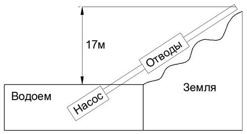
The steel (iron) pipe is laid with a length of 376 meters with an inner diameter of 100 mm, along the length of the pipe there are 21 bends (90 ° C bends). The pipe is laid with a drop of 17m. That is, the pipe goes up to a height of 17 meters relative to the horizon. Pump characteristics: Maximum head 50 meters (0.5MPa), maximum flow 90m 3 / h. Water temperature 16 ° C. Find the maximum possible flow rate at the end of the pipe.
| D = 100 mm = 0.1 m L = 376 m Geometrical height = 17 m Elbows 21 pcs Pump head = 0.5 MPa (50 meters of water column) Maximum flow = 90 m 3 / h Water temperature 16 ° C. Steel iron pipe |
Find the maximum flow rate =?
Solution on video:
To solve it, you need to know the pump schedule: The dependence of the flow rate on the head.
In our case, there will be a graph like this:
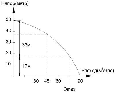
Look, I marked 17 meters with a dashed line on the horizon and at the intersection along the curve I get the maximum possible flow rate: Qmax.
According to the schedule, I can safely say that at the height difference, we lose approximately: 14 m 3 / hour. (90-Qmax = 14 m 3 / h).
The stepwise calculation is obtained because the formula contains a quadratic feature of head losses in dynamics (movement).
Therefore, we solve the problem stepwise.
Since we have a flow rate range from 0 to 76 m 3 / h, I would like to check the head loss at a flow rate equal to: 45 m 3 / h.
Finding the speed of water movement
Q = 45 m 3 / h = 0.0125 m 3 / sec.
V = (4 • 0.0125) / (3.14 • 0.1 • 0.1) = 1.59 m / s
Finding the Reynolds number
ν = 1.16 x 10 -6 = 0.00000116. Taken from the table. For water at a temperature of 16 ° C.
Δe = 0.1mm = 0.0001m. Taken from the table for a steel (iron) pipe.
Further, we check the table, where we find the formula for finding the coefficient of hydraulic friction.
I get to the second area under the condition
10 • D / Δe 0.25 = 0.11 • (0.0001 / 0.1 + 68/137069) 0.25 = 0.0216
Next, we finish with the formula:
h = λ • (L • V 2) / (D • 2 • g) = 0.0216 • (376 • 1.59 • 1.59) / (0.1 • 2 • 9.81) = 10.46 m.
As you can see, the loss is 10 meters. Next, we determine Q1, see the graph:
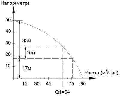
Now we make the original calculation at a flow rate equal to 64m 3 / hour
Q = 64 m 3 / h = 0.018 m 3 / sec.
V = (4 • 0.018) / (3.14 • 0.1 • 0.1) = 2.29 m / s
λ = 0.11 (Δe / D + 68 / Re) 0.25 = 0.11 • (0.0001 / 0.1 + 68/197414) 0.25 = 0.021
h = λ • (L • V 2) / (D • 2 • g) = 0.021 • (376 • 2.29 • 2.29) / (0.1 • 2 • 9.81) = 21.1 m.
We mark on the chart:
Qmax is at the intersection of the curve between Q1 and Q2 (Exactly the middle of the curve).
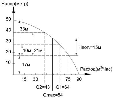
Answer: The maximum flow rate is 54 m 3 / h. But we decided this without resistance on the bends.
To check, check:
Q = 54 m 3 / h = 0.015 m 3 / sec.
V = (4 • 0.015) / (3.14 • 0.1 • 0.1) = 1.91 m / s
λ = 0.11 (Δe / D + 68 / Re) 0.25 = 0.11 • (0.0001 / 0.1 + 68/164655) 0.25 = 0.0213
h = λ • (L • V 2) / (D • 2 • g) = 0.0213 • (376 • 1.91 • 1.91) / (0.1 • 2 • 9.81) = 14.89 m.
Result: We hit Npot = 14.89 = 15m.
Now let's calculate the resistance when cornering:
The formula for finding the head at the local hydraulic resistance:
| h-head loss here it is measured in meters. ζ is the coefficient of resistance. For the knee, it is approximately equal to one if the diameter is less than 30mm. V is the fluid flow rate. Measured by [Meter / Second]. g-acceleration due to gravity is 9.81 m / s2 |
ζ is the coefficient of resistance. For a knee, it is approximately equal to one if the diameter is less than 30mm. For larger diameters, it decreases. This is due to the fact that the influence of the speed of movement of the water in relation to the turn is reduced.
Looked in different books on local resistances for turning pipes and bends. And he often came to the calculations that one strong sharp turn is equal to the coefficient of unity. A sharp turn is considered if the turning radius does not exceed the diameter by value. If the radius exceeds the diameter by 2-3 times, then the value of the coefficient decreases significantly.
Speed 1.91 m / s
h = ζ • (V 2) / 2 • 9.81 = (1 • 1.91 2) / (2 • 9.81) = 0.18 m.
We multiply this value by the number of taps and get 0.18 • 21 = 3.78 m.
Answer: at a speed of 1.91 m / s, we get a head loss of 3.78 meters.
Let's now solve the whole problem with taps.
At a flow rate of 45 m 3 / h, a head loss along the length was obtained: 10.46 m. See above.
At this speed (2.29 m / s) we find the resistance when cornering:
h = ζ • (V 2) / 2 • 9.81 = (1 • 2.29 2) / (2 • 9.81) = 0.27 m. multiply by 21 = 5.67 m.
Add the head losses: 10.46 + 5.67 = 16.13m.
We mark on the chart:
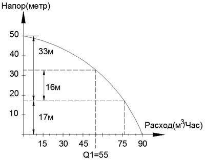
We solve the same only for a flow rate of 55 m 3 / h
Q = 55 m 3 / h = 0.015 m 3 / sec.
V = (4 • 0.015) / (3.14 • 0.1 • 0.1) = 1.91 m / s
λ = 0.11 (Δe / D + 68 / Re) 0.25 = 0.11 • (0.0001 / 0.1 + 68/164655) 0.25 = 0.0213
h = λ • (L • V 2) / (D • 2 • g) = 0.0213 • (376 • 1.91 • 1.91) / (0.1 • 2 • 9.81) = 14.89 m.
h = ζ • (V 2) / 2 • 9.81 = (1 • 1.91 2) / (2 • 9.81) = 0.18 m. multiply by 21 = 3.78 m.
Add losses: 14.89 + 3.78 = 18.67 m
Drawing on the chart:
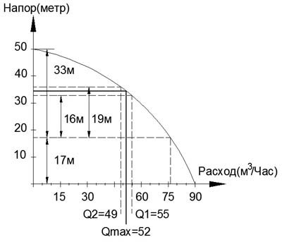
Answer:
Maximum flow rate = 52 m 3 / hour. Without bends Qmax = 54 m 3 / hour.
As a result, the size of the diameter is influenced by:
| 1. Resistance created by the pipe with bends 2. Required flow 3. Influence of the pump by its flow-pressure characteristic |
If the flow rate at the end of the pipe is less, then it is necessary: Either increase the diameter, or increase the pump power. It is not economical to increase the pump power.
This article is part of the system: Water heating constructor
Coolant speed
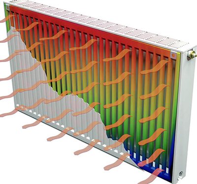
Then, using the obtained values of the coolant flow rate, it is necessary to calculate for each section of pipes in front of the radiators the speed of movement of water in pipes according to the formula
:
where V is the speed of movement of the coolant, m / s;
m - coolant flow through the pipe section, kg / s
ρ is the density of water, kg / m3. can be taken equal to 1000 kg / cubic meter.
f - cross-sectional area of the pipe, sq.m. can be calculated using the formula: π * r 2, where r is the inner diameter divided by 2
Coolant speed calculator
m = l / s; pipe mm by mm; V = m / s
Hydraulic calculation of the heating system, taking into account pipelines.
Hydraulic calculation of the heating system, taking into account pipelines.
When carrying out further calculations, we will use all the main hydraulic parameters, including the flow rate of the coolant, hydraulic resistance of fittings and pipelines, the speed of the coolant, etc. There is a complete relationship between these parameters, which is what you need to rely on in the calculations.
For example, if the speed of the coolant is increased, the hydraulic resistance at the pipeline will increase at the same time. If the flow rate of the coolant is increased, taking into account the pipeline of a given diameter, the speed of the coolant will simultaneously increase, as well as the hydraulic resistance. And the larger the diameter of the pipeline, the lower the speed of the coolant and the hydraulic resistance will be. Based on the analysis of these relationships, it is possible to turn the hydraulic calculation of the heating system (the calculation program is in the network) into an analysis of the parameters of the efficiency and reliability of the entire system, which, in turn, will help reduce the cost of the materials used.
The heating system includes four basic components: a heat generator, heating devices, piping, shut-off and control valves. These elements have individual parameters of hydraulic resistance, which must be taken into account when calculating. Recall that the hydraulic characteristics are not constant. Leading manufacturers of materials and heating equipment must provide information on specific pressure losses (hydraulic characteristics) for the equipment or materials produced.
For example, the calculation for polypropylene pipelines of the FIRAT company is greatly facilitated by the given nomogram, which indicates the specific pressure or head loss in the pipeline for 1 meter of running pipe. Analysis of the nomogram allows you to clearly trace the above relationships between individual characteristics. This is the main essence of hydraulic calculations.
Hydraulic calculation of hot water heating systems: heat carrier flow
We think you have already drawn an analogy between the term "coolant flow" and the term "amount of coolant". So, the flow rate of the coolant will directly depend on what heat load falls on the coolant in the process of transferring heat to the heating device from the heat generator.
Hydraulic calculation implies the determination of the rate of flow of the coolant in relation to a given area. The calculated section is a section with a stable coolant flow rate and a constant diameter.
Hydraulic calculation of heating systems: example
If the branch includes ten kilowatt radiators, and the coolant consumption was calculated for the transfer of heat energy at the level of 10 kilowatts, then the calculated section will be a cut from the heat generator to the radiator, which is the first in the branch. But only on condition that this area is characterized by a constant diameter. The second section is located between the first radiator and the second radiator. At the same time, if in the first case the consumption of 10-kilowatt thermal energy transfer was calculated, then in the second section the calculated amount of energy will already be 9 kilowatts, with a gradual decrease as the calculations are carried out. The hydraulic resistance must be calculated simultaneously for the supply and return pipelines.
Hydraulic calculation of a one-pipe heating system involves calculating the flow rate of the heat carrier
for the calculated area according to the following formula:
Quch is the thermal load of the calculated area in watts. For example, for our example, the heat load on the first section will be 10,000 watts or 10 kilowatts.
s (specific heat capacity for water) - constant equal to 4.2 kJ / (kg • ° С)
tg is the temperature of the hot heat carrier in the heating system.
tо is the temperature of the cold heat carrier in the heating system.
Hydraulic calculation of the heating system: flow rate of the heating medium
The minimum speed of the coolant should take a threshold value of 0.2 - 0.25 m / s. If the speed is lower, excess air will be released from the coolant. This will lead to the appearance of air locks in the system, which, in turn, can cause partial or complete failure of the heating system. As for the upper threshold, the speed of the coolant should reach 0.6 - 1.5 m / s. If the speed does not rise above this indicator, then hydraulic noise will not form in the pipeline. Practice shows that the optimal speed range for heating systems is 0.3 - 0.7 m / s.
If there is a need to calculate the speed range of the coolant more accurately, then you will have to take into account the parameters of the material of the pipelines in the heating system. More precisely, you need a roughness factor for the inner piping surface. For example, if we are talking about pipelines made of steel, then the optimal speed of the coolant is at the level of 0.25 - 0.5 m / s. If the pipeline is polymer or copper, then the speed can be increased to 0.25 - 0.7 m / s. If you want to play it safe, read carefully what speed is recommended by manufacturers of equipment for heating systems. A more accurate range of the recommended speed of the coolant depends on the material of the pipelines used in the heating system, and more precisely on the roughness coefficient of the inner surface of the pipelines. For example, for steel pipelines, it is better to adhere to the coolant speed from 0.25 to 0.5 m / s for copper and polymer (polypropylene, polyethylene, metal-plastic pipelines) from 0.25 to 0.7 m / s, or use the manufacturer's recommendations if available.
Calculation of the hydraulic resistance of the heating system: pressure loss
The loss of pressure in a certain section of the system, which is also called the term "hydraulic resistance", is the sum of all losses due to hydraulic friction and in local resistances. This indicator, measured in Pa, is calculated by the formula:
ΔPuch = R * l + ((ρ * ν2) / 2) * Σζ
ν is the speed of the used coolant, measured in m / s.
ρ is the density of the heat carrier, measured in kg / m3.
R is the pressure loss in the pipeline, measured in Pa / m.
l is the estimated length of the pipeline in the section, measured in m.
Σζ is the sum of the coefficients of local resistances in the area of equipment and shut-off and control valves.
As for the total hydraulic resistance, it is the sum of all hydraulic resistances of the calculated sections.
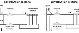
Hydraulic calculation of a two-pipe heating system: selection of the main branch of the system
If the system is characterized by a passing movement of the coolant, then for a two-pipe system, the ring of the most loaded riser is selected through the lower heating device. For a one-pipe system, a ring through the busiest riser.

Heat carrier consumption
The coolant flow rate is calculated by the formula:
Cp - specific heat capacity of water, kJ / (kg * deg. C); for simplified calculations, we take it equal to 4.19 kJ / (kg * deg. C)
ΔPt is the temperature difference at the inlet and outlet; usually we take the supply and return of the boiler
Heating agent consumption calculator
(only for water)
Q = kW; Δt = o C; m = l / s
In the same way, you can calculate the flow rate of the coolant at any section of the pipe. The sections are selected so that the water speed is the same in the pipe. Thus, the division into sections occurs before the tee, or before the reduction. It is necessary to sum up in terms of power all radiators to which the coolant flows through each section of the pipe. Then substitute the value into the formula above. These calculations need to be done for the pipes in front of each radiator.
The speed of movement of water in the pipes of the heating system.
At the lectures, we were told that the optimal speed of water movement in the pipeline is 0.8-1.5 m / s. On some sites I see something like that (specifically about the maximum one and a half meters per second).
BUT in the manual it is said to take losses per running meter and speed - according to the application in the manual. There, the speeds are completely different, the maximum, which is in the plate - just 0.8 m / s.
And in the textbook I met an example of calculation, where the speeds do not exceed 0.3-0.4 m / s.
Duck, what's the point? How to accept it at all (and how in reality, in practice)?
I attach a screen of the tablet from the manual.
Thank you in advance for your answers!
What do you want? To learn the "military secret" (how to actually do it), or to pass the course book? If only a term student - then according to the manual that the teacher wrote and knows nothing else and does not want to know. And if you do how to
, will not accept yet.
0.036 * G ^ 0.53 - for heating risers
0.034 * G ^ 0.49 - for branch lines, until the load decreases to 1/3
0.022 * G ^ 0.49 - for the end sections of a branch with a load of 1/3 of the entire branch
In the course book, I counted it like a manual. But I wanted to know how the situation was.
That is, it turns out in the textbook (Staroverov, M. Stroyizdat) is also not correct (speeds from 0.08 to 0.3-0.4). But perhaps there is only an example of calculation.
Offtop: That is, you also confirm that, in fact, the old (relatively) SNiPs are in no way inferior to the new ones, and somewhere even better. (Many teachers tell us about this. On the PSP, the dean says that their new SNiP in many ways contradicts both the laws and himself).
But in principle, they explained everything.
and the calculation for a decrease in diameters along the flow seems to save materials. but increases labor costs for installation. if labor is cheap, it might make sense. if labor is expensive, there is no point. And if, at a large length (heating main), changing the diameter is beneficial, within the house, fussing with these diameters does not make sense.
and there is also the concept of hydraulic stability of the heating system - and here ShaggyDoc schemes win
We disconnect each riser (upper wiring) with a valve from the main. Duck just met that right after the valve they put double adjustment taps. Is it advisable?
And how to disconnect the radiators themselves from the connections: valves, or put a double-adjustment tap, or both? (that is, if this crane could completely shut off the corpse pipeline, then the valve is not needed at all?)
And for what purpose are the sections of the pipeline isolated? (designation - spiral)
The heating system is two-pipe.
I specifically find out about the supply pipeline, the question is above.
We have a coefficient of local resistance at the inlet of a flow with a turn. Specifically, we apply it to the entrance through a louver into a vertical channel. And this coefficient is equal to 2.5 - which is quite a lot.
I mean, how to come up with something to get rid of it. One of the exits - if the grating is “in the ceiling”, and then there will be no entrance with a turn (although it will be small, since the air will be drawn along the ceiling, moving horizontally, and move towards this grating, turn in a vertical direction, but along logic, this should be less than 2.5).
In an apartment building, you can't make a grating in the ceiling, neighbors. and in a single-family apartment - the ceiling will not be beautiful with a lattice, and debris can get in. that is, the problem cannot be solved that way.
I often drill, then I plug it
Take heat output and start from end temperature. Based on this data, you will absolutely reliably calculate
speed. It will most likely be 0.2 mS maximum. Higher speeds - you need a pump.
Quick selection of pipe diameters according to the table
For houses up to 250 sq.m. provided that there is a pump of 6 and radiator thermal valves, you can not do a full hydraulic calculation. You can select the diameters from the table below. In short sections, the power can be slightly exceeded. Calculations were made for the coolant Δt = 10 o C and v = 0.5 m / s.
| Trumpet | Radiator power, kW |
| Pipe 14x2 mm | 1.6 |
| Pipe 16x2 mm | 2,4 |
| Pipe 16x2.2 mm | 2,2 |
| Pipe 18x2 mm | 3,23 |
| Pipe 20x2 mm | 4,2 |
| Pipe 20x2.8 mm | 3,4 |
| Pipe 25x3.5 mm | 5,3 |
| Pipe 26х3 mm | 6,6 |
| Pipe 32х3 mm | 11,1 |
| Pipe 32x4.4 mm | 8,9 |
| Pipe 40x5.5 mm | 13,8 |
Discuss this article, leave feedback in
Heat Supply News Magazine No. 1, 2005, www.ntsn.ru
Ph.D. O.D. Samarin, Associate Professor, Moscow State University of Civil Engineering
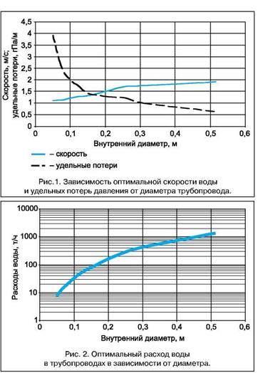
Currently existing proposals regarding the optimal speed of water movement in pipelines of heat supply systems (up to 3 m / s) and permissible specific pressure losses R (up to 80 Pa / m) are mainly based on technical and economic calculations. They take into account that as the speed increases, the cross-sections of pipelines decrease and the volume of thermal insulation decreases, i.e. the investment in the network device is reduced, but at the same time the operating costs for pumping water increase due to the increase in hydraulic resistance, and vice versa. Then the optimal speed corresponds to the minimum of the reduced costs for the estimated amortization period of the system.
However, in a market economy, it is imperative to take into account the discounting of operating costs E (rubles / year) and capital costs K (rubles). In this case, the formula for calculating the total discounted costs (CDC), when using borrowed funds, takes the following form:
In this case, the coefficients for discounting capital and operating costs, calculated depending on the estimated depreciation period T (years), and the discount rate p. The latter takes into account the level of inflation and investment risks, i.e., ultimately, the degree of economic instability and the nature of changes in current tariffs, and is usually determined by the method of expert estimates. As a first approximation, the value of p corresponds to the annual interest for a bank loan. In practice, it can be taken in the amount of the refinancing rate of the Central Bank of the Russian Federation. Starting from January 15, 2004, it is equal to 14% per annum.
Moreover, it is not known in advance that the minimum SDZ, taking into account discounting, will correspond to the same level of water velocity and specific losses that are recommended in the literature. Therefore, it is advisable to carry out new calculations using the current range of prices for pipelines, thermal insulation and electricity. In this case, if we assume that the pipelines operate under the conditions of a quadratic resistance mode, and calculate the specific pressure loss using the formulas given in the literature, for the optimal speed of water movement, the following formula can be obtained:
Here K ty is the coefficient of the rise in the cost of pipelines due to the presence of thermal insulation. When using domestic materials such as mineral wool mats, K ti = 1.3 can be taken. Parameter C D is the unit cost of one meter of the pipeline (rubles / m 2), referred to the inner diameter D (m). Since the price lists usually indicate the price in rubles per ton of metal C m, the recalculation must be made according to the obvious ratio, where is the pipeline wall thickness (mm), = 7.8 t / m 3 is the density of the pipeline material. The C el value corresponds to the electricity tariff. According to the data of Mosenergo OJSC for the first half of 2004 for communal consumers С el = 1.1723 rubles / kWh.
Formula (2) was obtained from the condition d (SDZ) / dv = 0. The determination of operating costs was carried out taking into account the fact that the equivalent roughness of the pipeline walls is 0.5 mm, and the efficiency of network pumps is about 0.8. The density of water p w was considered equal to 920 kg / m 3 for the characteristic temperature range in the heating network. In addition, it was assumed that the circulation in the network is carried out all year round, which is quite justified, based on the needs of hot water supply.
An analysis of formula (1) shows that for long amortization periods T (10 years and more), typical for heating networks, the ratio of the discount coefficients is practically equal to its limiting minimum value p / 100.In this case, expression (2) gives the lowest economically feasible water velocity corresponding to the condition when the annual interest on a loan taken for construction is equal to the annual profit from reducing operating costs, i.e. with an infinite payback period. At the end date, the optimum speed will be higher. But in any case, this rate will exceed that calculated without discounting, since then, as it is easy to see, but in modern conditions it is still 1 / T
The values of the optimal water velocity and the corresponding appropriate specific pressure losses calculated by expression (2) at the average level C D and the limiting ratio are shown in Fig. 1. It should be borne in mind that formula (2) includes the value D, which is unknown in advance, therefore, it is first advisable to set the average value of the velocity (about 1.5 m / s), determine the diameter at a given water flow rate G (kg / h), and then calculate the actual speed and optimal speed by (2)
and check if v f is greater than v opt. Otherwise, the diameter should be reduced and the calculation repeated. You can also get the ratio directly between G and D. For the average level C D, it is shown in Fig. 2.
Thus, the economically optimal water velocity in heating networks calculated for the conditions of a modern market economy, in principle, does not go beyond the limits recommended in the literature. However, this speed depends less on the diameter than if the condition for permissible specific losses is met, and for small and medium diameters, increased values of R up to 300 - 400 Pa / m are advisable. Therefore, it is preferable to further reduce capital investments (in
in this case - to reduce the cross-sections and increase the speed), and the more so, the higher the discount rate. Therefore, the desire to reduce one-time costs in the construction of engineering systems, which is in practice in some cases, receives a theoretical justification.
Literature
1. AA Ionin et al. Heat supply. Textbook for universities. - M .: Stroyizdat, 1982, 336 p.
2. V.G. Gagarin. The criterion for recoupment of costs for improving the thermal protection of building envelopes in different countries. Sat. report conf. NIISF, 2001, p. 43 - 63.
Individual hydraulic heating systems
In order to correctly carry out the hydraulic calculation of the heating system, it is necessary to take into account some of the operational parameters of the system itself. This includes the speed of the coolant, its flow rate, hydraulic resistance of valves and pipelines, inertia, and so on.
It may seem that these parameters are not related to each other in any way. But this is a mistake. The connection between them is direct, so it is necessary to rely on them in the analysis.
Let's give an example of this relationship. If you increase the speed of the coolant, then the resistance of the pipeline will immediately increase. If you increase the flow rate, then the speed of hot water in the system increases, and, accordingly, the resistance. If you increase the diameter of the pipes, then the speed of movement of the coolant decreases, which means that the resistance of the pipeline decreases.
The heating system includes 4 main components:
- Boiler.
- Pipes.
- Heating devices.
- Shut-off and control valves.
Each of these components has its own resistance parameters. Leading manufacturers must indicate them, because the hydraulic characteristics can vary. They largely depend on the shape, design and even on the material from which the components of the heating system are made. And it is these characteristics that are most important when conducting a hydraulic analysis of heating.
What is hydraulic performance? This is the specific pressure loss. That is, in every type of heating element, be it a pipe, valve, boiler or radiator, there is always resistance from the side of the device structure or from the side of the walls.Therefore, passing through them, the coolant loses its pressure, and, accordingly, its speed.
Everyone should know the standards: parameters of the heating medium of the heating system of an apartment building
Residents of apartment buildings in the cold season more often trust the maintenance of the temperature in the rooms to the already installed batteries central heating.
This is the advantage of urban high-rise buildings over the private sector - from mid-October to the end of April, utilities take care of constant heating living quarters. But their work is not always perfect.
Many have encountered insufficiently hot pipes in winter frosts, and with a real heat attack in the spring. In fact, the optimal temperature of an apartment at different times of the year is determined centrally, and must comply with the accepted GOST.
Heating standards PP RF No. 354 of 05/06/2011 and GOST
May 6, 2011 was published Government Decree, which is valid to this day. According to him, the heating season depends not so much on the season as on the air temperature outside.
The central heating starts to work, provided that the external thermometer shows the mark below 8 ° C, and the cold snap lasts at least five days.
On the sixth day the pipes are already starting to heat the premises. If warming occurs within the specified time, the heating season is postponed. In all parts of the country, batteries delight with their warmth from mid-autumn and maintain a comfortable temperature until the end of April.
If frost has come and the pipes remain cold, this may be the result system problems. In the event of a global breakdown or incomplete repair work, you will have to use an additional heater until the malfunction is eliminated.
If the problem lies in air locks that have filled the batteries, contact the operating company. Within 24 hours after submitting the application, a plumber assigned to the house will arrive and "blow through" the problem area.
The standard and norms of permissible air temperature values are spelled out in the document "GOST R 51617-200. Housing and communal services. General technical information ". The range of air heating in the apartment may vary from 10 to 25 ° C, depending on the purpose of each heated room.
- Living rooms, which include living rooms, study bedrooms and the like, must be heated to 22 ° C.Possible fluctuation of this mark up to 20 ° Cespecially in cold corners. The maximum value of the thermometer should not exceed 24 ° C.
The temperature is considered optimal. from 19 to 21 ° C, but zone cooling is allowed up to 18 ° C or intense heating up to 26 ° C.
- The toilet follows the temperature range of the kitchen. But, a bathroom, or an adjoining bathroom, are considered rooms with a high level of humidity. This part of the apartment can warm up up to 26 ° Cand cool up to 18 ° C... Although, even with the optimal allowable value of 20 ° C, using the bath as intended is uncomfortable.
- The comfortable temperature range for corridors is considered to be 18–20 ° C.... But, decreasing the mark up to 16 ° C found to be quite tolerant.
- The values in the pantries can be even lower. Although the optimal limits are from 16 to 18 ° C, marks 12 or 22 ° C do not go beyond the boundaries of the norm.
- Entering the staircase, the tenant of the house can count on an air temperature of at least 16 ° C.
- A person is in the elevator for a very short time, hence the optimum temperature is only 5 ° C.
- The coldest places in a high-rise building are the basement and the attic. The temperature can go down here up to 4 ° C.
The warmth in the house also depends on the time of day. It is officially recognized that a person needs less warmth in a dream. Based on this, lowering the temperature in the rooms 3 degrees from 00.00 to 05.00 in the morning is not considered a violation.
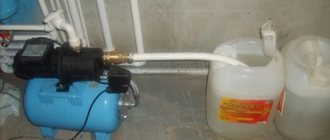
Selection and installation of the pump
There are a number of factors to consider when choosing a pump:
- What kind of coolant will be used, what will be its temperature.
- Line length, pipe material and pipe diameter.
- How many radiators (and which ones - cast iron, aluminum, etc.) will be connected, what will be their size.
- The number and types of valves.
- Will there be automatic regulation, and how exactly it will be organized.
Installing the pump on the "return" extends the service life of all parts of the circuit. It is also advisable to install a filter in front of it to prevent damage to the impeller.
Before installation, the pump is deaerated.
Choice of coolant
Water can be used as a coolant, as well as one of the antifreezes:
- Ethylene glycol. A toxic substance that can be fatal. Since leaks cannot be completely ruled out, it is better not to use it.
- Aqueous solutions of glycerin. Their use requires the use of better quality sealing elements, non-polar rubber parts, some types of plastics; Installation of an additional pump may be required. Causes increased metal corrosion. In places of heating to high temperatures (in the area of the boiler burner), the formation of a poisonous substance - acrolein is possible.
- Propylene glycol. This substance is non-toxic, moreover, it is used as a food additive. Eco-antifreezes are made on its basis.
The design calculations for all heating circuits are based on the use of water. If antifreeze is used, all parameters should be recalculated, since antifreeze is 2-3 times more viscous, has a much larger volumetric expansion, and a lower heat capacity. This means that much more powerful (by about 40% - 50%) radiators, higher boiler power, and pump head are required.
Heating medium temperature parameters in the heating system

The heating system in an apartment building is a complex structure, the quality of which depends on correct engineering calculations even at the design stage.
The heated coolant must not only be delivered to the building with minimal heat loss, but also evenly distribute in rooms on all floors.
If the apartment is cold, then a possible reason is the problem with maintaining the required temperature of the coolant during the ferry.
Optimal and maximum
The maximum battery temperature has been calculated based on safety requirements. To avoid fires, the coolant must be 20 ° C colderthan the temperature at which some materials are capable of spontaneous combustion. The standard indicates safe marks in the range 65 to 115 ° C.
But, the boiling of the liquid inside the pipe is extremely undesirable, therefore, when the mark is exceeded at 105 ° C can serve as a signal to take measures to cool the coolant. The optimum temperature for most systems is at 75 ° C. If this rate is exceeded, the battery is equipped with a special limiter.
Minimum
The maximum possible cooling of the coolant depends on the required intensity of heating the room. This indicator directly associated with the outside temperature.
In winter, in frost at –20 ° C, the liquid in the radiator at the initial rate at 77 ° C, should not be cooled less than up to 67 ° C.
In this case, the indicator is considered the normal value in the return at 70 ° C... During warming to 0 ° C, the temperature of the heating medium may drop up to 40–45 ° C, and the return up to 35 ° C.