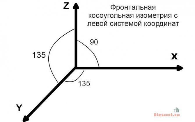
| Fig. one ... Position of axonometric axes. |
The Uniform Requirements for the Execution of Construction Drawings states the following:
"... the diagrams of the systems are performed in an axonometric frontal isometric projection on a scale of 1: 100 or 1: 200, the nodes of the circuits are on a scale of 1:10, 1:20 or 1:50."
The position of the axonometric axes is shown in Fig. 2.
It is allowed to use frontal isometric projections with an angle of inclination of the y-axis of 30 ° and 60 °.
Frontal isometric projection is performed without distortion along the x, y, z axes. The determination of the position of the axes is shown in Fig. one.
System diagrams are performed in axonometric frontal isometric projection on a scale "- says paragraph 3.2.1 of GOST 21.602-79. In the educational literature on construction drawing, they explain: “axonometric schemes are performed in frontal isometry with a left axis system and a distortion coefficient along the axes, conventionally taken as a unit, which makes it possible to use a metric scale when constructing.
ORDER OF PERFORMANCE OF THE TASK
Internal cold water supply design
The design of the water supply of a residential building is carried out in accordance with the requirements of SNiP 2.04.01-85 and SNiP 2.04.03-85.
2.1.1 Internal water supply
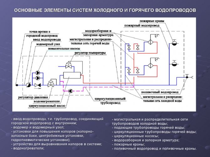
The water supply system includes the following elements: input, water meter unit, internal water supply network (distribution mains, risers, connections to water taps) and installations for increasing the water pressure in the network.
2.1.2. Selection of the system and circuit of the internal cold
Plumbing
1. Depending on the initial data, the following internal water supply systems of buildings are possible in the work:
a) an internal drinking water supply system powered directly from the city network without booster devices (H gar
2. There is only one input for a building with a dead-end network of an internal water supply system, since a temporary interruption of the water supply is allowed.
The entrance to the building is laid in its central part with a slope 0,005 from the building and connected to the water supply network with the help of a nurse. It is designed from cast iron plumbing pipes d = 32 mm according to GOST 5525-61.
The length of the bushing should be as small as possible, and the diameter of its pipes is determined by calculation. Input length ℓ
= 15 m
(the pipe is sealed in the place of its passage through the building foundation using a metal sleeve d = 250 mm and inserts in the annular gap of the resin strand and oily mint clay). At the point of connection of the input to the external network, a well is provided for placing the connecting and shut-off valves.
The depth of the bushing is assigned depending on the depth of the pipes of the street water supply network and the depth of soil freezing.
The inlet is laid with a slope from the building above the drainage pipes and away from them at the distances recommended by SNiP 2.04.01-85.
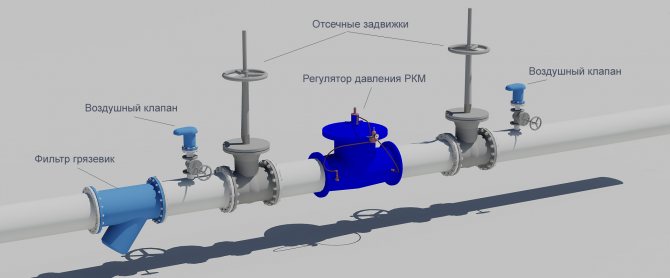
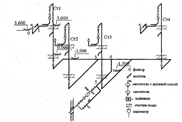
3. The water metering unit and water meters are located near the outer wall, immediately after the pipes are introduced into the building, in the central part of the basement, where the temperature is 2 ° C. The selected area is available for inspection, meter reading and on-site repair.
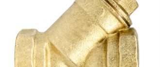
In internal water supply systems, as a rule, high-speed meters are used: vane or turbine. Vane meters are installed horizontally only; turbine - in any position. On each side of the meter, there should be straight pipe sections on which valves or valves are installed.
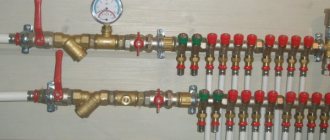
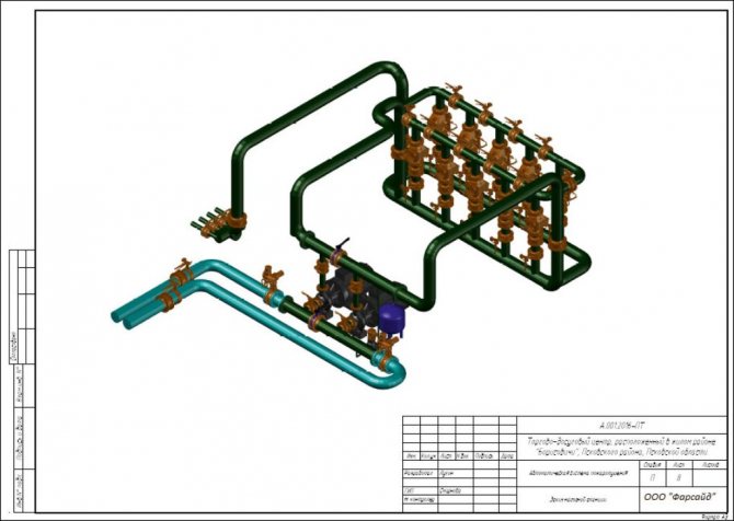
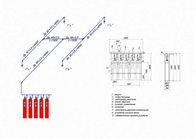
A drain valve should be installed between the meter and the second (according to the water flow) valve, valve. If there is one entrance to the building, a bypass line is arranged at the meter with a valve, sealed at the usual time in a closed position. The device of the water metering unit is shown in Fig. 2.
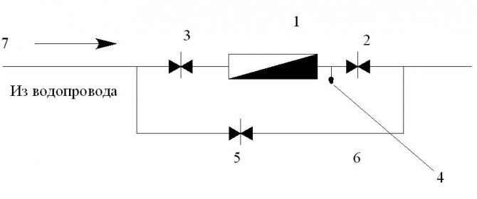
Fig. 2
... Water metering unit and its main elements.
1
- water meter (water meter);
2
- locking device to the water meter;
3
- shut-off device after the water meter;
4
- control and drain valve;
5
- a sealed gate valve on the bypass line;
6
- bypass line;
7
- main pipeline.
2.1.3. Internal water supply network device
When designing a water supply network, you need to strive for the smallest length of pipelines. The main line is laid under the basement ceiling with a slope 0,002 towards the water metering unit. On the main line, in places where sanitary devices are concentrated (in sanitary facilities), 5 risers are installed, necessary for distributing water across the floors of the building.
An open laying of risers is provided. Leads to water taps and appliances are laid 0.25 m above the floor.
Shut-off valves are installed at the base of each riser; on each connection to the toilet cistern; on branches to each apartment; in front of external watering taps. The internal water supply system provides for two watering taps, one for every 60–70 m of the building perimeter, located in the niches of the outer walls of the building.
The internal trunk network, risers and connections to devices and watering taps are designed from galvanized steel gas-supply pipes GOST 3242-75.
Risers are located in the bathrooms.
Displaying communications in a drawing
When working with a project for internal water supply and sewerage, general drawings are prepared on which water supply and sewerage are combined. In axonometric diagrams, these networks are always separated. The horizontal sections of the networks are transferred to the projection horizontally. On the plan, the risers are located near the serviced group of devices, indicated by large dots. On the diagram, they are built vertically. The riser farthest from the input is shown in full. The rest of the elements are carried out partially, indicating their brand. Vertical drawing of risers allows you to display the valves installed on them.
System parts displayed vertically on the project plan are drawn at an angle of 45 °. According to the routing, the cold water supply is laid 0.3 m above the floor, located with a slope of 0.002 towards the riser. This position is necessary to drain the liquid. The connection to the water fittings is carried out vertically.
All elements and nodes of the pipeline have their own marking and serial number in the drawing. Legend shows stop valves, taps, plumbing fixtures, water meters. In the manufacture of axonometry, the norms for the installation height of water consumption points are applied:
- sink and sink faucet - 1.1 m;
- bath tap - 0.8 m;
- connection to the water heater - 0.8 m;
- connection to the flush cistern - 0.65 m;
- fire hydrant - 1.35 m.
To shut off the water flow in the event of an emergency and for preventive maintenance of the system, shut-off valves (taps, gate valves) are installed. They are placed in key locations:
- at the base of the risers (in a building from 3 floors);
- at the entrances to apartments, branches to tanks, water heaters, showers;
- at the point of connection to the street network;
- on watering valves;
- in the water metering unit.
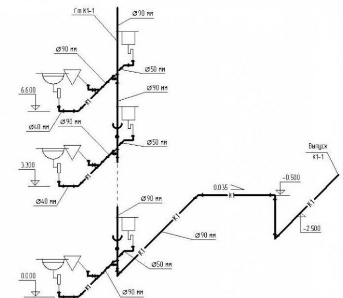
Features of sketch design
Here attention is focused on the reflection of the devices. If one element climbs onto another, and this happens in most cases, then a dotted line is drawn, indicating the displacement of the plumbing element in order to improve the visual effect
The axonometric diagram of the water supply system should include readings of all pipe diameters. If the toilet bowl is not marked on the outlet, then a diameter of 50 mm is taken, if there is one, the minimum diameter should be 100 mm
These numbers are important to remember. For risers, in 90% of cases, an indicator of 100 mm is used
Slopes in a similar diameter will be 0.02, with an indicator of 50 mm, an angle of inclination of 0.03 is set.
If you have already applied all the elements, mark the outlets, the diameter of which is larger than that of the risers, the number of 0.02 is taken as the slope.
At the last stage of drawing up the axonometry, special marks are made based on the characteristics of the site and the construction plan. Here they note the level of freezing of the soil, the location of the foundation, as well as other factors affecting the edits.
Output
In the article, I told what an axonometric diagram of the water supply system of a house is, showed several examples of such schemes for a private house and apartment.
© Elesant.ru
More articles
- Abyssinian well, a simple way of individual water supply
- Automatic pumping station
- Drilling artesian water wells
- Do-it-yourself water drilling for water supply at home, cottage, summer cottage
- Drilling a well for water: stages of work of a professional team
- Types and selection of a surface pump of a private house
- Types of water supply systems
- Vortex pump: device and application
- Plumbing in a private house: a device for introducing water to a private house
- Water supply of a country house from a well
Hydraulic calculation of cold water supply
The hydraulic calculation of the cold water supply network begins after the constructive solution of the entire scheme of the cold water supply system, drawing an axonometric design diagram of the supply pipelines of the entire settlement building and quarter.
The purpose of the hydraulic calculation of the internal cold water supply is to determine the estimated costs, pipe diameters and pressure losses in the calculated sections and in the entire system in such a way as to ensure uninterrupted water supply to all consumers in the building with the required pressure.
Hydraulic calculation is carried out in the following sequence:
A dictating point is selected taking into account the distance and height of the location of the water-folding fittings, as well as the magnitude of the free head
for sanitary appliances.
The network is divided into calculated sections. Estimated
is called the section, the flow rate of which
permanent: sections of the pipeline between the points of connection of the supply lines of the water-folding fittings
to apartment wiring, apartment wiring to risers, risers to: mains. Breakdown into calculated areas is carried out against the course of water movement, starting from the dictating point.
The number of devices served by the calculated site is determined. In this case, watering taps are not included in the calculation.
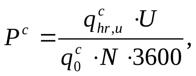
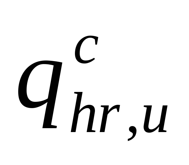
At each site, the estimated water consumption is determined, l / s:
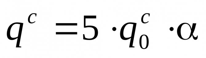
,
(4.4.1)
Where

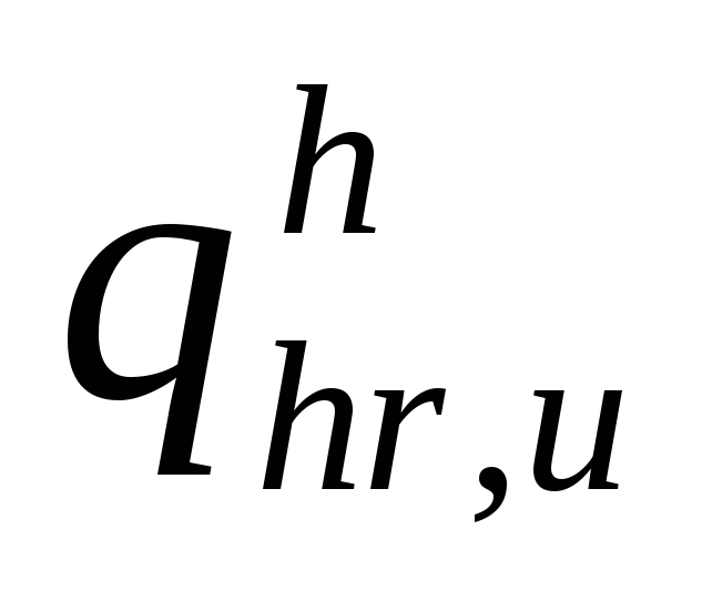
–
maximum second flow rate of cold water, l / s, referred to one device. Its value is determined by the device, the flow rate of which is the highest. Consumption by one device

is determined in accordance with clause 3.2.
but
–
value determined depending on the total number of devices N in the calculated area and the probability of their action
Rfrom.
Its value is determined from the table. 2 app. four .
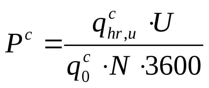
The likelihood of instrument action Rc
for various sections of the network is determined immediately for the entire building as a whole (since the ratio
UN
= const).
(4.4.2)
Where U –
the number of residents in the house;
N –
the number of all water-folding devices;
- the rate of consumption of cold water by one consumer per hour of the highest water consumption, l / h (Appendix 3).
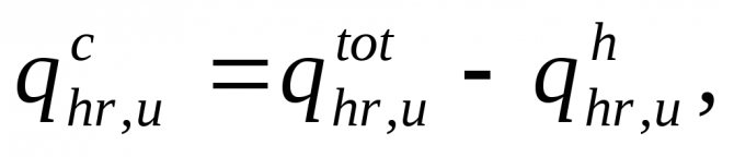
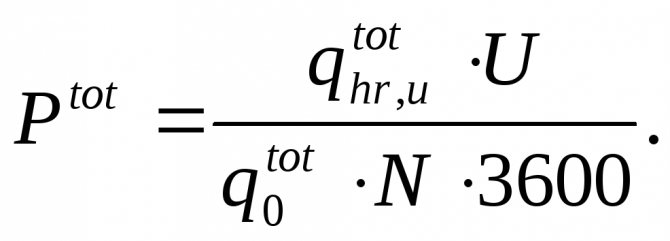
(4.4.3)
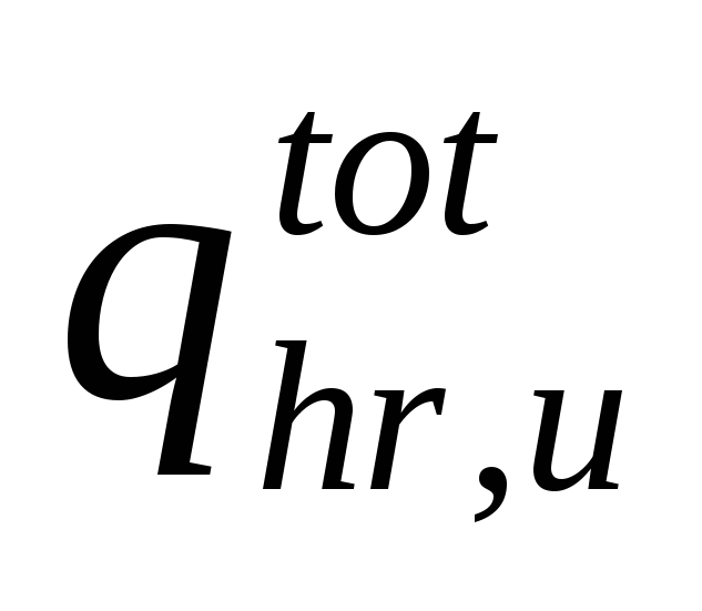
– about
the general rate of water consumption by the consumer per hour of the highest water consumption, l / h (Appendix 3);
- the rate of consumption of hot water by one consumer per hour of the highest water consumption, l / h (Appendix 3).
The diameters of the pipes are selected from the table. for hydraulic calculation of water pipes according to estimated flow rates and permissible speeds. It should be borne in mind that the speed of water movement in the pipelines of internal water supply networks should not exceed 3 m / s. When selecting the inner diameters of cold water supply pipelines, one should be guided by the economical speed of water movement, which for pipes d 40 mm –
within 0.9 ... 1.2 m / s.
Head loss, m, in sections of pipelines of cold water supply systems should be determined by the formula:
h =
i—l-(l +kl),
(4.4.4)
Where i–
specific frictional head losses, mm / m;
/ –
length of the calculated section, m;
k–
coefficient that takes into account the head loss in local resistances. In the networks of utility and drinking water supply systems of residential buildings,
kt=0,3.
Along the main path from the dictating point to the city water supply, the amount of pressure losses is calculated.
It is convenient to perform hydraulic calculation in tabular form.
If there are risers different in load (number of devices) on the axonometric diagram, there may be doubts about the correctness of the choice of the dictating point. Therefore, to accurately find the dictating point, it is necessary to find the vanishing point (see Table 4.4.1.) Of different risers (usually on the main) and, relative to it, find the sum of pressure losses on one and the other branches, taking into account the difference in the geometric height of the installation of different devices (if for dictating points are taken by different devices) and the required pressures necessary for their normal operation. Large losses determine the dictating riser and the location of the dictating point. Such a calculation is also necessary to draw up a specification of materials and equipment for the entire house, since it is necessary to determine the diameters of all risers and sections of the highway. In this case, the table will take the form:
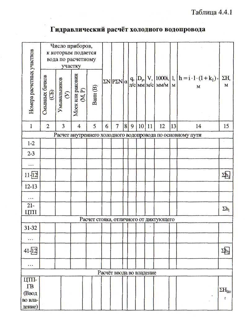
(
);
Comparing values
and
... A riser is selected as the dictator, the value
which is more.
Note:
It should be remembered that the section from the central heating station to the city water supply
(takeover) should be calculated at

and
.

Sewerage system installation
Installation of external sewerage networks
Sewerage installation schemes will fully comply with the plan you have developed. But the question arises - where to start editing? Best from a riser. And here it is important to take the correct pipe diameter:
- From the toilet to the riser - 110 millimeters.
- From bathroom to riser - 50-80 millimeters.
- From the sink - 32 millimeters.
- From the kitchen - 50 millimeters.
In terms of external sewerage, the best option is 110 millimeters. If the volume of water used is large, then 200 millimeters. By the way, the installation of an external network can be started from any edge - even from a septic tank, even from home. It is important here, as in the case of the inner part, to correctly set the slope, which is 2.0-3.0 millimeters per one running meter of the length of the sewer pipe.
Outdoor sewage systems and schemes are quite simple. But still it must be borne in mind that a gravity network should not have a large number of turns and connections. And also try to plan the sewerage before additional buildings and structures are erected on the site.
What to look for when sketching
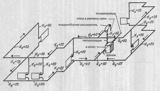
Before reflecting the axonometric scheme of heating a room in a paper version or in electronic form, a number of calculations are carried out. The scheme itself is drawn up based on the collected data:
- heat demand values for building rooms;
- typology of heating devices, their quantity for each of the premises;
- basic decisions regarding the entire engineering network: the use of risers, the calculation of hydraulic branches and circuits, the procedure for connecting the elements of the heating system;
- characteristics of pipeline sections: diameters and lengths of pipe fragments, valves, thermal controllers, hydraulic regulators.
Having received the corresponding calculations, their indicators are entered into the scheme. The axonometric diagram of the heating system necessarily contains the technical characteristics of each of the network nodes (boilers and pumps used), the length and diameter of pipes, heat consumption and information on other thermal properties of heating devices, such as radiators, convectors, registers.
Starting to work on an axonometric drawing, first of all, the main ring of movement of the coolant is determined - the path to the most distant of the elements from the boiler and back.
Summing up the studied, let's say that axonometry is performed without fail, regardless of the type of communication system for structures of any type of purpose. Having a graphic drawing in front of their eyes, installers quickly determine how much work needs to be done and how the network looks.
If a specialist understands the axonometric heating scheme, and the drawing itself is made correctly without any errors, then in the course of the project it is possible to exclude the occurrence of any difficulties associated with the installation of elements of the heating system, pipeline and other engineering networks.
In order for the design, and after the installation of the water supply system, to be successful, it is necessary to correctly visualize the building itself and the communication branches inside it on a sheet or in electronic form. In this case, the graphic component of the project includes:
- general layout of the building;
- situational scheme;
- facade;
- plans for each of the floors;
- roof plan;
- axonometric diagrams: ventilation, heating, water supply;
- cuts and other concepts.
Remember that when working with a correctly designed axonometry, problems with the installation of engineering networks in 99.9% of cases do not arise. Therefore, this stage is so important in designing a future house or high-rise building.
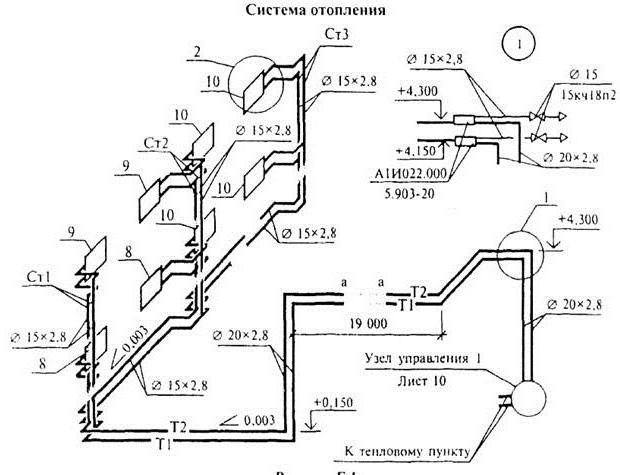
Heating schemes for private houses are different. For example, one- or two-circuit, with natural or forced circulation of the coolant, but when the phrase "axonometric diagram of the heating system" is pronounced, many wonder what kind of scheme it is. To know what an axonometric heating scheme is, you need to imagine what an axonometry is in principle.
An example of an axonometric heating scheme
Design work
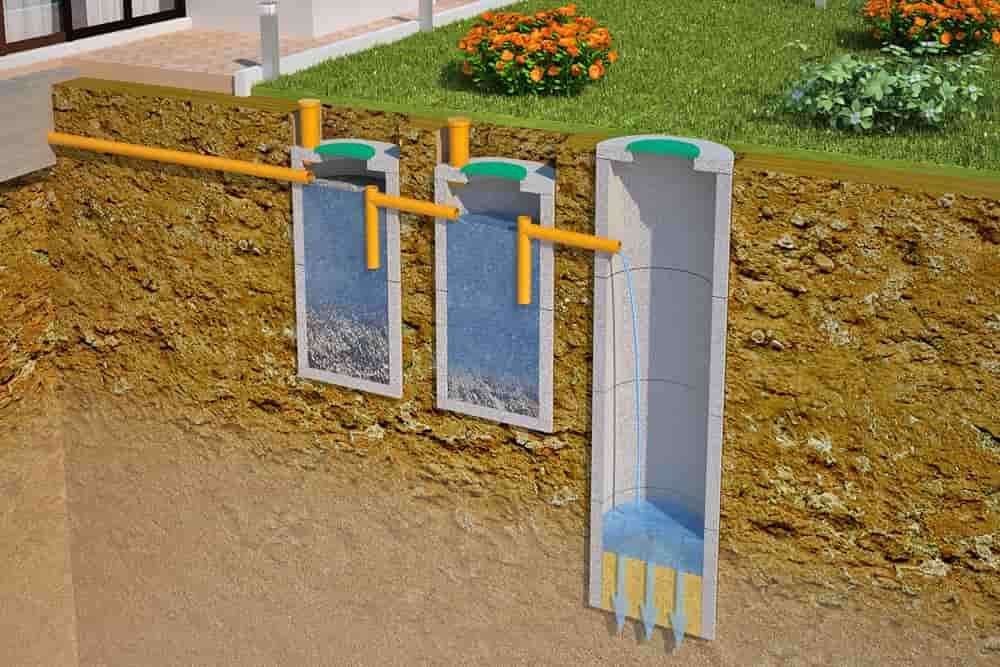
The general scheme of the sewerage device is an assembly of pipelines, on the one hand, connected to plumbing, and on the other, to treatment facilities. However, for the installation of a specific section of the sewerage complex, a detailed and accurate drawing is required. When calculating the project, it is necessary to ensure the requirements of SNiP, as well as sanitary standards for the placement of elements. Basic requirements for a sewerage project:
- sufficient throughput with some margin in case of extreme discharge of effluents;
- correctly calculated configuration, consistent pipe slope;
- tracing should be as straight as possible, without sharp turns;
- in the direction of the flow of drains, pipes of a smaller diameter should be connected to pipes of a larger size, and not vice versa;
- the track must be equipped with a standard number of inspection chambers or revision elements.
The sewerage system diagram is drawn up taking into account its size, purpose and specific use. The task of the compiler includes competent tracing, excluding abrupt changes in the direction of the line. In addition, it is necessary to provide for the technologically correct arrangement of pipes, the corresponding position of the plumbing outlet elements. In the process of creating a project, an axonometric diagram of the sewage system of a residential building is often used. It gives an idea of the spatial position of elements and pipelines. For complex structures with a multi-layer structure, this version of the drawing is much more convenient and clear.
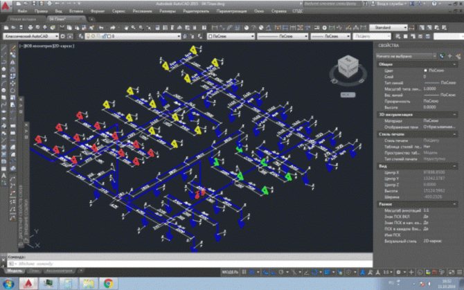
How to display structural elements electronically
The fastest way to build a drawing is by cloning the entire schematic. To do this, select the "Insert" command, after which the integrated image is inverted. In order for the function to be executed, it is given a value of 45 degrees (a number is written in the program).
Having prepared the basis in the electronic version, where the risers are marked on the plan, they put symbols in the form of dots. A vertical line is drawn to reflect all floors in the building. For the purpose of better perception, floor panels are reflected in the diagram.

Important! Don't make the slabs too long. Take advantage of the gap
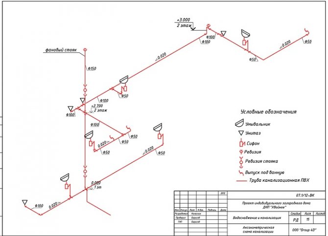
The peculiarity of the axonometric sewerage scheme is the reflection of all elements of sanitary devices: urinals, toilets, sinks, ladders and other devices for carrying out hygiene procedures.
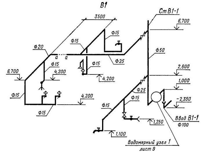
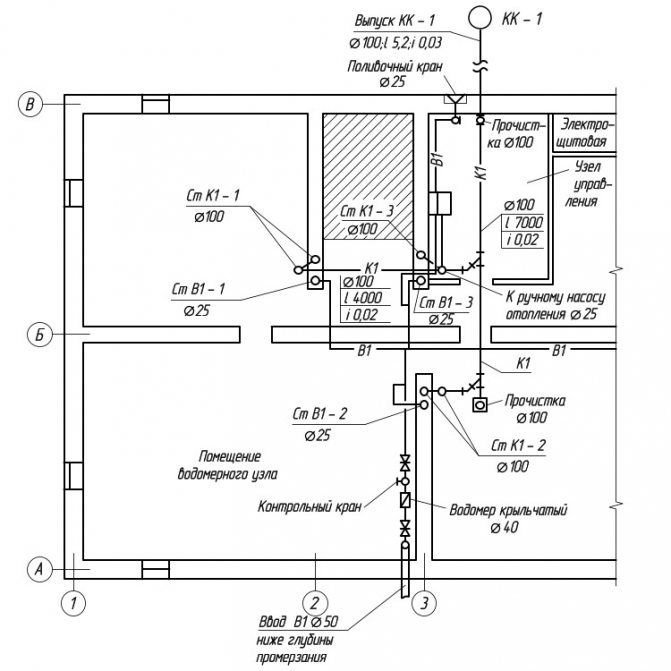
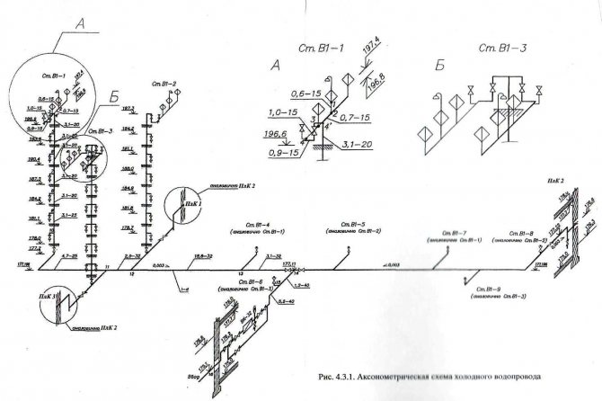
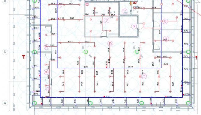
Ground floor plan
This plan shows the risers of sanitary units located in the grooves of the capital walls: water supply (StV1-1 ... StV1-3), sewage (StK1-1 ... StK1-3) and hot water supply (StV1-1 ... StV1-3). The diameters of these piping systems are also stamped.
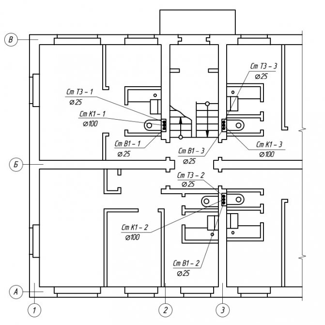
Fragment of the ground floor plan
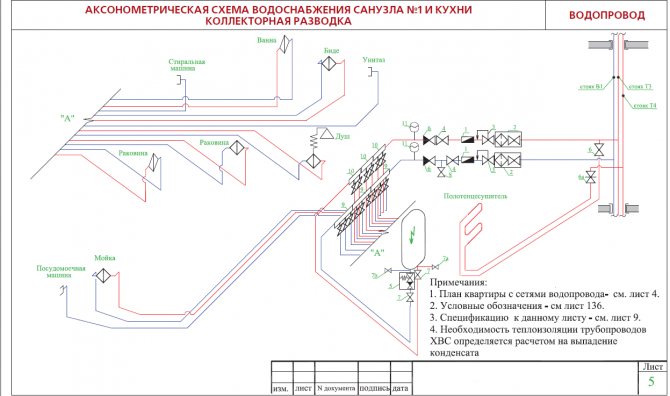
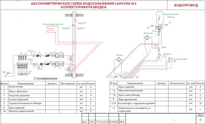
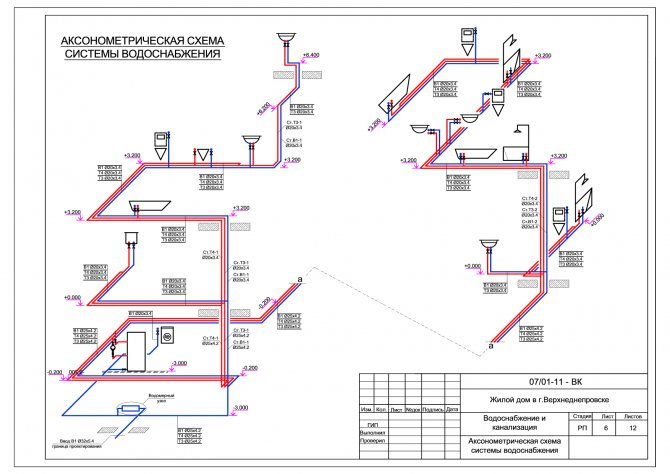
The designed pipeline networks, which are applied to the plans, are the basis on which the axonometric diagrams of plumbing systems are carried out. These diagrams provide a more visual representation of how the various elements of a building's piping systems are positioned relative to each other.
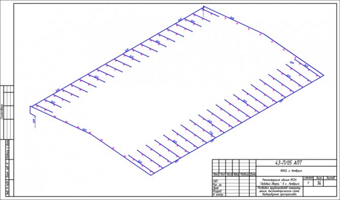
Axonometry of water supply, heating, sewerage
According to GOST 2.317-2011, all axonometric diagrams related to sanitary systems of water supply, sewerage, heating are built in frontal dimetric (oblique) isometry with a left coordinate system.
Accordingly, the dimensions along the z and x axes will be without distortion, and along the y axis by half.
What does this drawing have to do with pipes and plumbing, you ask? Now imagine that the planes along the axonometric axes are the walls of your house or apartment. Plumbing pipes, water supply lines, sewerage and heating pipes run along the walls, vertically or horizontally. This means that we can draw pipe paths in axonometry without showing the walls themselves.
This will give very clear drawings of how and where to install the plumbing wiring. Moreover, plumbing fixtures are applied to the axonometric diagram in symbols, pipe diameters are applied, explanations are made, tables on materials and equipment are compiled for the diagrams. As a result, you have in your hands a detailed guide on how to install plumbing fixtures in a house (apartment), practically eliminating installation errors.


Materials (edit)
The optimal and most common option for materials for sewage is plastic pipes.
Their advantages include the following qualities:
- low cost;
- ease of transportation and installation;
- good performance.
In addition to pipes, fittings are required: elbows, fittings, tees and revisions. You will also need a sealant to process the joints.
The choice of the diameter of the pipes for the sewage system depends on the required capacity of the system and the number of connected plumbing fixtures. This data should contain a private house sewerage project. Whatever pipe diameter is used, each outlet pipe must have sufficient throughput, for which the pipe diameter must exceed the diameter of the outlet of the plumbing device. For the riser, pipes with a diameter of 100 mm (if there is a toilet) or from 50 mm (if there is none) are usually used. The pipes from the devices to the riser should be shorter than 3 m, and from the toilet bowl - shorter than 1 m.If these indicators are not achieved, then the diameter of the pipes in these areas must be increased.
Determination of axonometric heating scheme
Axonometry is one of the areas of applied drawing that studies, examines and provides the opportunity to obtain sufficiently accurate images of any objects in two or three projections. Rectangular axonometric projection is when the lines that project the image of an object are located perpendicular to the axonometric projection plane.The rectangular projection includes isometric and dimetric. If the projection angle is not equal to 90 °, then such a projection is called oblique axonometric. It also includes frontal dimetric and trimetric projections.
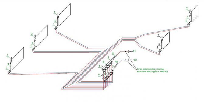
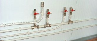
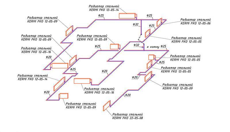
Collector wiring in oblique axonometric projection
It follows that an axonometric heating scheme is any scheme of any heating of a multi- or small-storey building, made in axonometry, and not in one plane. This helps to visualize the wiring and other elements of the heating system in real terms. With this approach to displaying heating elements, the projection of each object is performed as follows:
- The element is located on the diagram according to all three coordinate axes;
- The "picture plane" is defined - the element will be projected onto it. In this case, the "picture plane" should not run parallel to any of the coordinate axes;
- The projected node or element is completely transferred to the diagram.
Requirements for drawing up drawings of heating and other systems of a residential or industrial building are defined in GOST 21.602-2003. All heating elements and assemblies in accordance with GOST have their own designations: these are markings and serial numbers included in the drawing. The following conventions are used:
| Element or node | Marking |
| Heating riser | St |
| Main heating riser | Gst |
| Compensator | TO |
| Horizontal piping | GW |
| Thermometer | T |
| Pressure gauge | R |

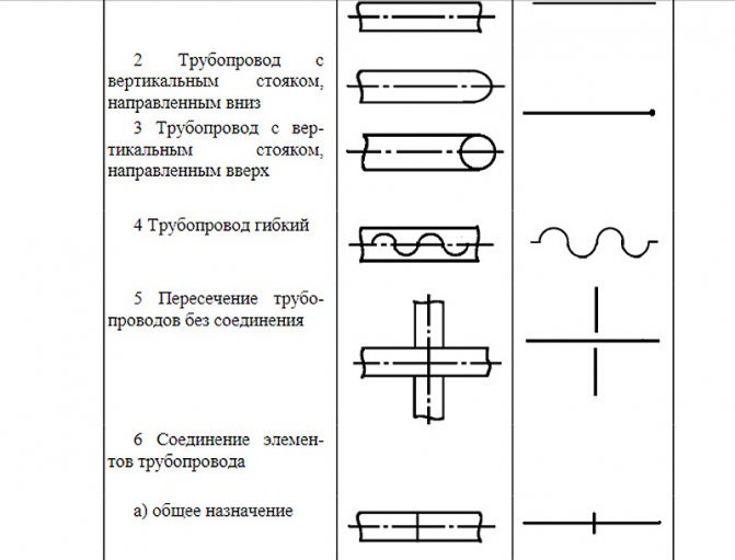
Fragment of GOST 21.206-93 on the designation of pipes and pipeline connections
According to GOST 21.206-93, pipeline systems are indicated graphically. This applies to such nodes:
- Common pipeline;
- Downward-facing vertical riser;
- Vertical riser upward;
- Flexible pipeline;
- Pipe crossing without connection;
- Simple connection of the pipeline or its elements;
- The connection of the pipeline or its elements is flanged;
- Coupling threaded connection;
- Coupling quick disconnect;
- Socket connection.
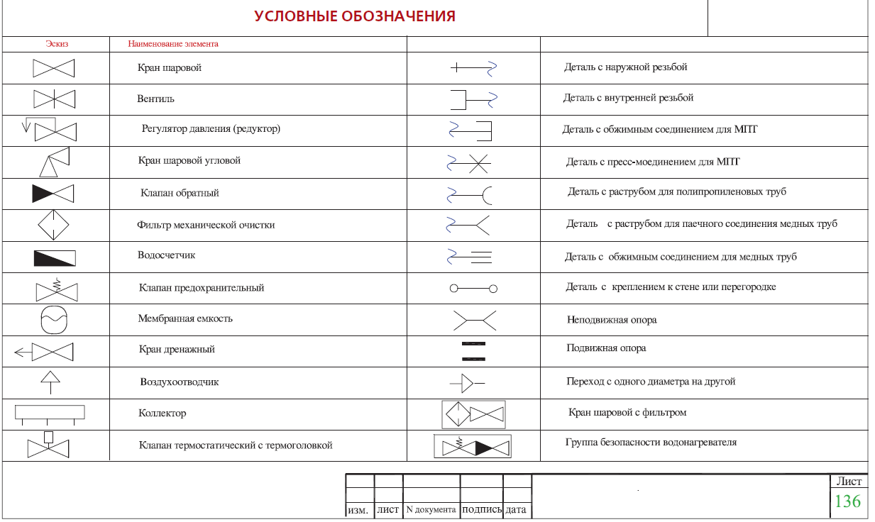
Designations of valves, radiators and other elements are shown in GOST 21.205-93. For example, such as:
- Washbasin;
- Foot bath;
- Toilet;
- Heating thermostat;
- Shower net;
- Air Dryer.
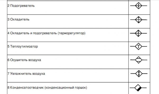
Fragment of GOST 21.205-93 on the designation of valves
Any axonometry cannot be displayed by standard means allowed in GOST, and for this there are additional requirements and permissions. For example:
- Elevations of heights and levels can be set out outside the element or indicated directly on the contours of objects;
- An axonometric drawing of a heating circuit with a lower wiring or any other circuit can be performed on a scale of 1:50, 1: 100 or 1: 200.


List of equipment and parameters on the diagram
The heating scheme of any floor should indicate:
- Piping with indication of all pipe diameters;
- Pipe insulation sections - length and thickness. Such insulation is indicated graphically;
- Piping axis relative to zero level;
- Pouring slope angles;
- If there are gaps in the horizontal sections of the filling, then the sizes of these sections are indicated;
- Supporting and suspension elements, expansion joints.
Mandatory requirement: you must specify the type and main characteristics of these elements:
- How many sections does the heating radiator contain;
- How many sections or pipes are in the heating register, its diameter and total length;
- For other heating devices (convectors, radiators) - the type of device;
- Designations of heating installations (boilers, heating furnaces and heat exchangers, circulation and heat pumps, elevators, etc.);
- Mortgage equipment;
- Measuring instruments.

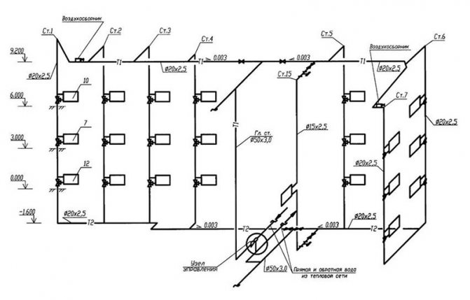
Heating diagram to scale
Heating equipment and calculations
All equipment used in the heating system is divided into auxiliary and main.The main one is a boiler or other heating device, the auxiliary one is radiators and distribution pipes with the attached fittings. To calculate the parameters of the necessary heating equipment, the specific power of the boiler is required, which varies depending on the climatic zones:
- For the regions of the Far North - 1.5-2.0 kW;
- For a temperate climatic zone and central regions - 1.2-1.5 kW;
- For the southern zones - 0.7-0.9 kW.
Based on these amendments, the power of the heating device is calculated using the formula:
Wboiler = S x W / 10;
Where W is the estimated power of the heating device (boiler, convector, etc.);
S is the total area of the heated object.
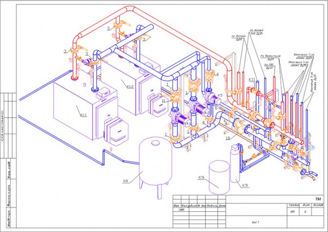
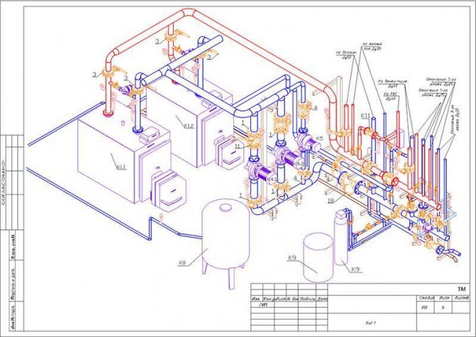
Axonometric diagram of boiler equipment with two burners
Pumps are heat and circulating. In most cases, except for low-rise buildings with natural circulation of the coolant, it is impossible to do without pumping equipment, therefore, in almost all schemes, these devices are present. Pumps must meet certain technical requirements, including the following:
- Ease of installation, dismantling, ease of operation and maintenance;
- Low noise and efficiency of the device;
- Reliability and durability of operation.
Three types of heating systems are used in low-rise residential buildings:
- The classic two-pipe scheme, according to which hot water is supplied through one pipe and returned through the second. In this scheme, the pump is mounted on the return line;
- Diagram with a vertical riser. In this scheme, hot water is also supplied to the radiators through one pipe, and returned through the second, but the circulation pump is installed on the outlet pipe to supply the hot coolant. Thus, hot water first passes through the upper radiators, and then moves to the lower batteries of the system;
- The one-pipe scheme assumes the movement of the coolant sequentially from the radiator to the radiator with a return to the boiler. This is the simplest scheme, but due to its low efficiency, it is used in small one-story buildings.
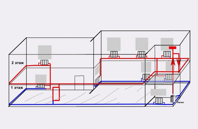
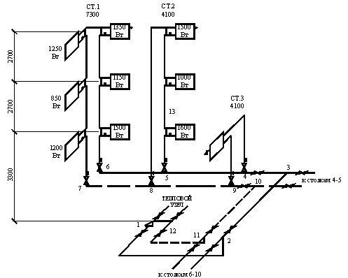
Simplified axonometric two-pipe diagram
Calculations when drawing up a heating scheme should take into account:
- Heat consumption in each room;
- Type and number of radiators;
- The number of risers, if any, as well as the total number of branches and circuits;
- Heating device connection diagram;
- Parameters of pipes and valves.
After finishing the calculations of the heating system, they must be indicated on the diagram. The main purpose of the axonometric heating scheme is a graphical display of all parts and elements, but, in addition, the diagram should also display the technical characteristics of the heating equipment. Also, the scheme should contain calculations for the supply of heat to each room of the house, including utility rooms.


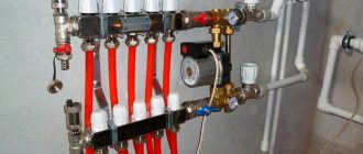
What is manifold piping
With manifold heating pipes, heating pipes are supplied to the heating radiators from a single distribution unit. The dispensing unit (collector) is a device with one inlet and several outlets of the coolant. Each outlet of the heating medium (water) is independently shut off by a shut-off valve. That is, if necessary, you can separately turn off any radiator of the heating system, independently of the others.
For the distribution of heating from the collector to the heating radiators, it is carried out with plumbing pipes suitable for heating systems. Used for heating:
- steel heating pipes,
- metal-plastic pipes,
- polyethylene and polypropylene pipes (hot water supply),
- copper pipes.
Heating pipes are connected by special devices called fittings. Heating pipes can have one or two types of connections. This is how metal-plastic pipes are connected at crimp fittings and press fittings. Polypropylene pipes are connected with weld fittings.Copper pipes are connected at press fittings and compression fittings. Steel pipes are connected, with a classic threaded connection, on cast or brass fittings.
Features of drawings
When drawing up an axonometric diagram, pay attention to the following points:
- Plumbing and other devices connected to the risers and the distribution network are reflected only when there are no necessary diagrams in the attached documentation.
- The zero mark (the level of the first floor) is shown on the risers by drawing a thin horizontal line. In the case of detailing the project, each of the nodes of the drawing is considered separately, reflecting it on an enlarged scale.
- If necessary, the sketches of diagrams and drawings of water supply networks and sewerage systems include symbols for shut-off and control valves, watering taps and other elements of systems.
What data is indicated when drawing up a diagram
The diagram of the water network of the building indicates:
- image and marking of risers;
- the place where the pipeline is connected to the building;
- floor branch of the wiring;
- shut-off and control valves;
- the height of the level of the location of plumbing fixtures;
- dimensions of pipeline sections (in mm);
- floor marks of all floors;
- water meter unit in the basement;
- watering taps.
On the diagrams, using the leader, the diameter of the pipes is indicated, the nozzles that are used when changing the dimensions of the wiring. It is necessary to note the places of water discharge, fire hydrants, instrumentation.