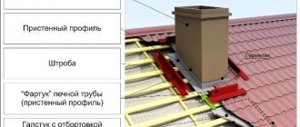
Nuances of aerodynamic calculations
The calculation of the boiler room chimney should take into account the following nuances:
- Taking into account the technical characteristics of the boiler, the type of trunk structure is determined, as well as the place in which the chimney will be located.
- The strength and durability of the gas outlet duct is calculated.
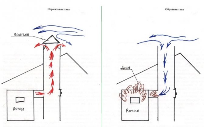
- It is also necessary to calculate the height of the chimney, taking into account both the volume of fuel burned and the type of draft.
- Calculation of turbulators for chimneys.
- The maximum boiler room load is calculated by determining the minimum flow rate.
Important! For these calculations, it is also necessary to know the wind load and the thrust value.
- At the last stage, a drawing of the chimney with optimization of the sections is created.
Aerodynamic calculations are necessary to determine the pipe height when using natural thrust. Then it is also necessary to calculate the rate of propagation of emissions, which depends on the relief of the territory, the temperature of the gas flow, and the air velocity.
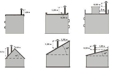
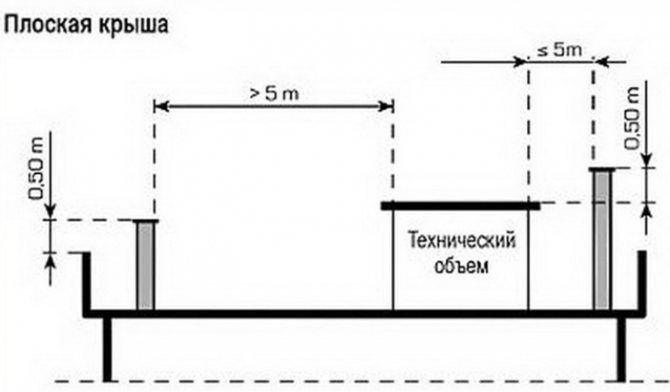
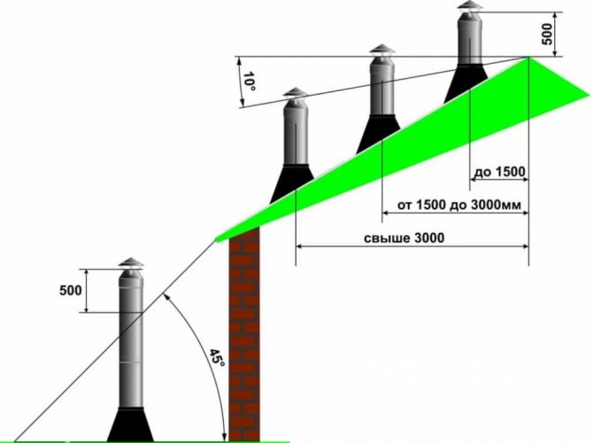
Determination of the chimney height for ridge and flat roofs
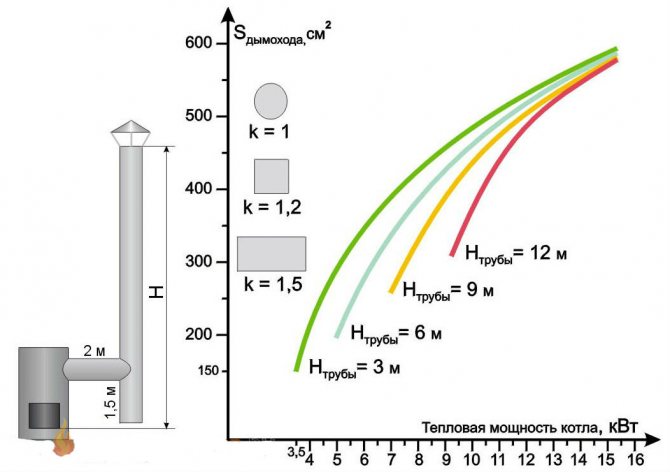
The height of the pipe directly depends on the power of the boiler. The flue duct pollution factor should not exceed 30%.
Formulas for calculating the chimney with natural draft:
Normative documents used in calculations
All design standards required for the creation of boiler plants are spelled out in SNiP ІІ-35-76. This document is the basis for all necessary calculations.
Video: an example of calculating a chimney with natural draft
The passport for the chimney contains not only the technical characteristics of the structure, but also information regarding its application and repair. This document must be issued just before the chimney is put into operation.
Advice! Repairing chimneys is a dangerous job that must be carried out exclusively by a specialist, as it requires specially acquired knowledge and a lot of experience.
Environmental programs set standards for permissible concentrations of pollutants such as sulfur dioxide, nitrogen oxides, ash, etc. A sanitary protection zone is considered to be an area located 200 meters around the boiler house. Various types of electrostatic precipitators, ash collectors, etc. are used to clean flue gases.
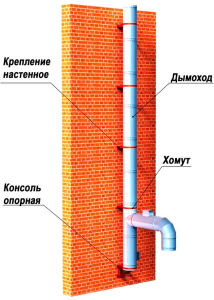
Chimney design with wall mount
Regardless of the fuel that the heater is running on (coal, natural gas, diesel fuel, etc.), a combustion product evacuation system is essential. For this reason, the main requirements for chimneys are:
- Having enough natural cravings.
- Compliance with established environmental standards.
- Good bandwidth.
Features of ventilation of workshops of various directions
Mechanical workshop
The features of the industrial mechanical room are a large heat emission from electrical equipment and workers, the presence of aerosol vapors, coolants, oil, emulsions, dust in the air.
Ventilation in such workshops is installed of a mixed type. Local suction units are located directly above the machines and work areas, and the elements of the general exchange system provide fresh air inflow from above, in the calculation of at least 30 cubic meters. for one person.
Woodworking
The peculiarities of the woodworking premises are the constant release of heat from the presses, the evaporation of toxic substances of the solvent and glue, as well as an increased concentration of woodworking waste - dust, shavings, sawdust.
In such workshops, local suction is installed directly into the floor to ensure the removal of wood waste. The general exchange system distributes the air flow in the upper zone, through the perforated type air ducts.
Galvanic
The peculiarity of the galvanic shop is the presence in the atmosphere of the room of vapors of alkali, acid, electrolyte, an increased amount of heat and moisture, dust, hydrogen.
Local on-board suction units are installed directly above acid solution baths. It is compulsory to equip suction units for acid baths with various types of backup fans and elements for filtering the extracted air masses.
The general exchange system, made of anti-corrosion material, must provide 3-fold air exchange in the compartments for the preparation of solutions and cyanide salts.
Welding
The peculiarity of the welding shop is the presence of fluoride compounds, nitrogen oxide, carbon, ozone in the air. In such production areas, local suction is desirable but not required. The general exchange hood should provide air removal in the amount of: 2/3 from the lower zone, 1/3 from the upper. Calculation of air for dilution of harmful emissions from welding to the maximum permissible level is based on the weight of the welding electrodes, which are consumed in 1 hour.
Casting
The main feature of the foundry is the huge amount of heat that is generated during the production process. In addition, ammonia, sulfur dioxide, carbon monoxide are concentrated in the atmosphere of the room.
Local suction units are installed at every machine and piece of equipment. The general exchange system is used only with mechanical induction in the upper zone of the workshop. Added to this is aeration and spraying of workplaces.
Types of chimneys for boiler rooms
Today there are several variants of chimneys used in boiler rooms. Each of them has its own characteristics.
Metal pipes for boiler rooms
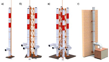
Types of metal chimneys. Each type of pipe must meet environmental standards a) single-mast, b) two-mast, c) four-mast, d) wall mounting
They are a very popular option due to the following features:
- ease of assembly;
- due to the smooth inner surface, the structures are not prone to clogging with soot, and therefore are able to provide excellent traction;
- quick installation;
- if necessary, such a pipe can be installed with a slight slope.
We advise you to study how the chimney height is calculated on our website.
Important! The main disadvantage of steel pipes is that their thermal insulation becomes unusable after 20 years, which causes the destruction of the chimney under the influence of condensate.
Brick pipes
For a long time they had no competitors among the chimneys. Currently, the difficulty in installing such structures lies in the need to find an experienced stove-maker and significant financial costs for the purchase of the necessary materials.
With the correct arrangement of the structure and a competent firebox, soot formation is practically not observed in such chimneys. If such a structure was installed by a professional, then it will serve for a very long time.
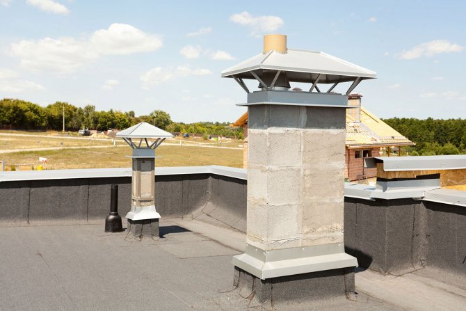
Chimney made of bricks
It is very important to check both internal and external masonry for correct joints and corners. To improve traction, an overflow is carried out at the top of the pipe, and in order to prevent smoke from forming in the presence of wind, a durable stationary hood is used.
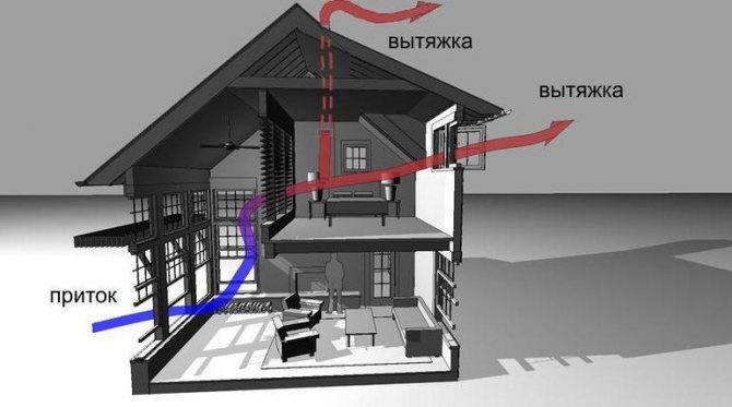
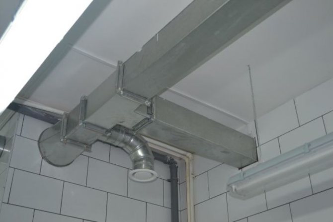
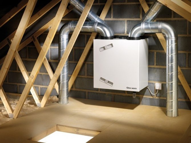
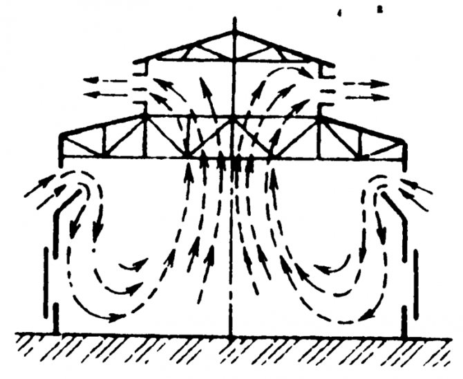
Performance standards and natural ventilation ducts
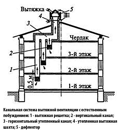
Duct exhaust ventilation system with natural induction.
The best option for the location of the channels is a niche in the wall of the building. When laying, it should be remembered that the best traction will be with a flat and smooth surface of the air ducts. To service the system, that is, cleaning, you need to design a built-in hatch with a door. So that debris and various sediments do not end up inside the mines, a deflector is installed above them.
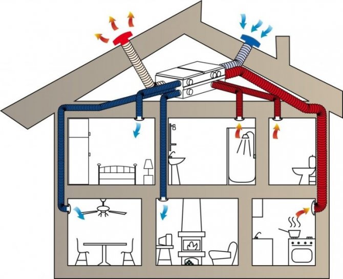
According to building codes, the minimum system performance should be based on the following calculation: in those rooms where people are constantly there, a complete air renewal should take place every hour. For other premises, the following should be removed:
- from the kitchen - at least 60 m³ / hour when using an electric stove and at least 90 m³ / hour when using a gas stove;
- bath, toilet - at least 25 m³ / hour, if the bathroom is combined, then at least 50 m³ / hour.
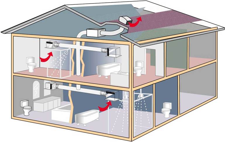
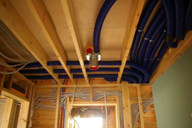
When designing a ventilation system for cottages, the most optimal model is one in which a common exhaust pipe is laid through all rooms. But if this is not possible, then the ventilation ducts are laid from:
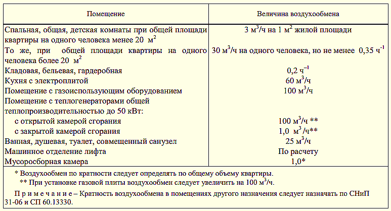
Table 1. Frequency rate of ventilation air exchange.
- bathroom;
- kitchens;
- pantry - provided that her door opens into the living room. If it leads to the hall or the kitchen, then you can only equip the supply channel;
- boiler room;
- from rooms that are delimited with rooms with ventilation by more than two doors;
- if the house is several floors, then, starting from the second, if there are entrance doors from the stairs, channels are also laid from the corridor, and if not, from each room.
When calculating the number of channels, it is necessary to take into account how the floor on the ground floor is equipped. If it is wooden and mounted on logs, then a separate passage is provided for ventilation of air in voids under such a floor.
In addition to determining the number of air ducts, the calculation of the ventilation system includes determining the optimal cross-section of the channels.
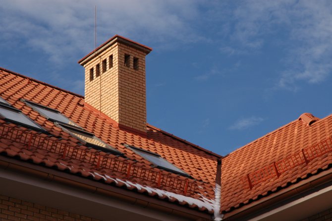
Boiler room chimney design
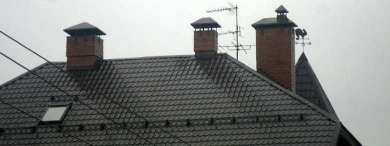
The chimney can be either located on the heating equipment, or stand separately, adjacent to the boiler or stove. The pipe must be 50 cm higher than the roof height. The size of the chimney in the section is calculated in relation to the power of the boiler room and its design features.
The main structural elements of the pipe are:
- gas outlet shaft;
- thermal insulation;
- anti-corrosion protection;
- foundation and support;
- a structure designed to enter gas ducts.
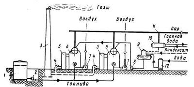
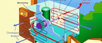
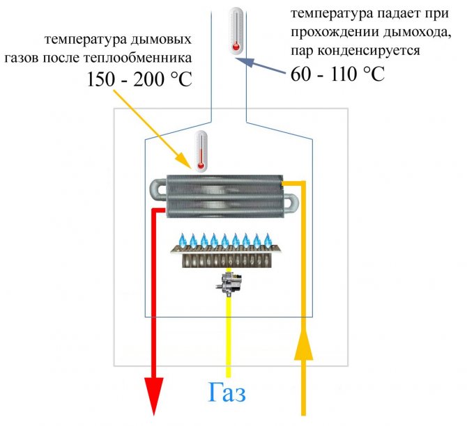
Diagram of the device of a modern boiler plant
At first, the flue gas enters the scrubber, which is a cleaning device. Here, the smoke temperature drops to 60 degrees Celsius. After that, bypassing the absorbers, the gas is purified and only after that it is released into the environment.
Important! The efficiency of the boiler-house power plant is largely influenced by the gas velocity in the channel, and therefore a professional calculation is simply necessary here.
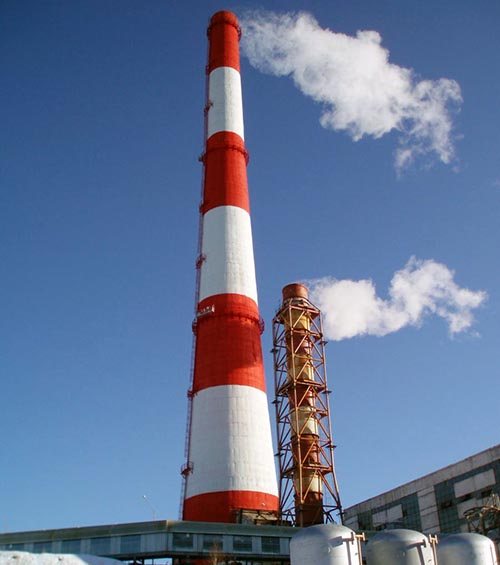
Chimney types
In modern boiler power plants, various types of chimneys are used. Each of them has its own characteristics:
- Columnar. Consists of an inner barrel made of stainless steel and an outer shell. Thermal insulation is provided here to prevent the formation of condensation.
- Near-facade. Attached to the facade of the building. The design is presented in the form of a frame with gas pipes. In some cases, specialists can do without a frame, but then anchoring on anchor bolts is used and sandwich pipes are used, the outer channel of which is made of galvanized steel, the inner channel is made of stainless steel, and a sealant 6 cm thick is located between them.
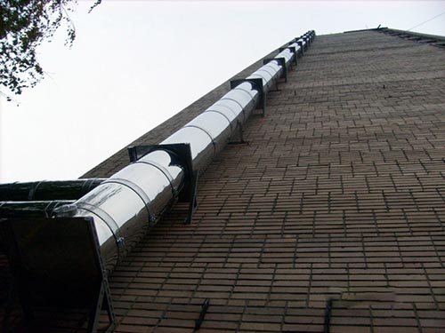
Construction of a near-facade industrial chimney
- Farm. It can consist of one or several concrete pipes. The truss is installed on an anchor basket fixed to the base.The design can be used in earthquake-prone areas. Paint and primer are used to prevent corrosion.
- Mast. Such a pipe has screeds, and therefore is considered more stable. Anti-corrosion protection is realized here in the form of a heat-insulating layer and refractory enamel. It can be used in areas with increased seismic hazard.
- Self-supporting. These are "sandwich" pipes, which are fixed to the base by means of anchor bolts. They are characterized by increased strength, which allows structures to withstand any weather conditions with ease.
Calculation of mechanical ventilation
Correctly and efficiently working ventilation keeps the air clean and reduces the amount of harmful emissions it contains.
Ventilation by the method of air induction can be forced (mechanical) or natural.
Mechanical ventilation according to the principle of operation can be supply, exhaust, or supply and exhaust.
Supply ventilation is used in industrial premises with a significant release of heat at a low concentration of harmful substances in the air, as well as to increase the air pressure in rooms with a local release of harmful substances in the presence of local exhaust ventilation systems. This prevents the spread of such substances throughout the room.
Exhaust ventilation is used to actively remove air that is uniformly contaminated throughout the entire volume of the room, at low concentrations of harmful substances in the air and a small rate of air exchange. In this case, the air exchange rate, h-1, is determined by the formula:
k = L / Vin, (3.324)
where L is the volume of air removed from the room or supplied to the room, m3 / h;
Vvn - internal volume of the room, m3.
Supply and exhaust ventilation is used when there is a significant release of harmful substances into the air of premises, in which it is necessary to ensure particularly reliable air exchange with increased frequency.
When designing mechanical exhaust ventilation, the density of the removed vapors and gases should be taken into account. Moreover, if it is less than the air density, then the air inlets are located in the upper part of the premises, and if it is more, in their lower part.
The release into the atmosphere of polluted air removed by mechanical ventilation should be provided above the roof of buildings.
The release of air through holes in the walls without the device of shafts brought out above the roof is not allowed. As an exception, the release can be provided through openings in the walls and windows, if harmful substances will not be introduced into other rooms.
Explosive gases should be released into the atmosphere at a horizontal distance equal to at least 10 equivalent diameters (in area) of the exhaust pipe, but not less than 20 m from the place of flue gas discharge.
Local exhaust ventilation is arranged in places with significant emission of gases, vapors, dust, aerosols. Such ventilation prevents the ingress of hazardous and harmful substances into the air of industrial premises.
Local exhaust ventilation should be used at gas and electric welding stations, metal-cutting and sharpening machines, in blacksmith shops, galvanic installations, battery shops, at service stations, in rooms near the starting points of tractors and cars.
Process emissions, as well as air emissions containing dust, toxic gases and vapors, must be cleaned before they are released into the atmosphere.
The volume of air that must be supplied to a room with the required parameters of the air environment in the working or serviced area should be calculated based on the amounts of heat, moisture and incoming harmful substances, taking into account the uneven distribution of them over the area of the room. In this case, the amount of air removed from the working or serviced area by local exhaust devices and general ventilation is taken into account.
If it is difficult to determine the amount of harmful substances released, the calculation of air exchange is carried out in accordance with the Sanitary Standards, which indicate: "In production facilities with a volume of less than 20 m3 per worker - at least 20 m3 / h for each worker."
If several unidirectional harmful substances are emitted into the air of the working area, then when calculating general ventilation, the air volumes required for diluting each substance should be summed up. Harmful substances of unidirectional or homogeneous action affect the same systems of the body, therefore, when one component of the mixture is replaced by another, the toxicity of the mixture does not change. For example, mixtures of hydrocarbons, strong mineral acids (sulfuric, hydrochloric, nitric), ammonia and nitrogen oxides, carbon monoxide and cement dust have a unidirectional action. In this case, the permissible content of harmful substances is determined by the formula:
(3.325)
where C1, C2, ..., Ci - concentration of harmful substances in the room air, mg / m3;
gpdk1, gpdk2,…, gpdki - maximum permissible concentration (MPC) of harmful substances, mg / m3.
At the next design stage, a design diagram of the duct network is drawn up, on which local exhaust devices and resistances (elbows, turns, dampers, expansions, contractions), as well as the numbers of the calculated network sections, are indicated. The calculated section is an air duct through which the same volume of air passes at the same speed.
According to the amount of air passing in the duct per unit of time, and its total pressure, a centrifugal fan is selected according to its aerodynamic characteristics. When selecting a fan, it is necessary to ensure the maximum value of the efficiency of the unit and reduce the noise level during operation.
In accordance with the Building Norms and Rules, a fan of the required design is selected: conventional, anti-corrosion, explosion-proof, dust. The required power of the electric motor is calculated, according to which the electric motor of the corresponding design is selected. The method of connecting the electric motor to the fan is selected.
Determine the method of processing the supply air: cleaning, heating, humidification, cooling.
Emissions into the atmosphere of air containing harmful substances removed from the systems of general exhaust ventilation, and the dispersion of these substances should be provided for and justified by calculation in such a way that their concentrations do not exceed the maximum daily average values in the atmospheric air of settlements.
The degree of purification of emissions of air containing dust is taken according to Table 3.128.
Table 3.128 - Permissible dust content in air emissions
depending on its MPC in the air of the working area of industrial
premises
| MPC of dust in the air of the working area of industrial premises, mg / m3 | Permissible dust content in the air emitted into the atmosphere, mg / m3 |
| ≤ 2 | |
| from 2 to 4 | |
| from 2 to 6 | |
| from 6 to 10 |
If the dust content in the air emissions does not exceed the values specified in Table 3.128, then this air is allowed not to be purified.
To clean the air removed from the premises, inertial and centrifugal dust separators are used, as well as filters of various designs.
To calculate mechanical ventilation, the following initial data are required: the purpose of the room and its dimensions, the nature of the pollution; purpose and quantity of equipment, materials that emit harmful substances and heat radiation; characteristics of pollution by fire hazard; fire hazard of premises; the maximum permissible concentration of harmful substances in the room, the concentration of contaminants in the supply air.
Example 3.11. In the welding department of the repair shop, at each of the four available welding stations, G = 0.6 kg / h of OMA-2 electrodes are consumed. When burning 1 kg of electrodes, the specific emission of manganese is q = 830 mg / kg. It is necessary to calculate the exhaust network of the general exchange supply and exhaust ventilation (Fig.3.19), providing the required state of the air environment, provided that all welders work simultaneously. Take the air temperature in the room to 22 ° С.
Fig. 3.19. Scheme for calculating the exhaust network of the ventilation system:
I… V - numbers of calculated sections; 1… 4 - local resistances: 1 - blinds at the entrance; 2 - knee with a rotation angle α = 90 °; 3 - sudden expansion of the hole at F1 / F2 = 0.7; 4 - fan diffuser
Decision.
Hourly volume of air removed by the exhaust ventilation of one welding station:
m3 / h,
where gpdk is the maximum permissible concentration of manganese with its content in welding aerosols up to 20% (gpdk = 0.2 mg / m3).
The total amount of air removed by the exhaust ventilation:
Ltot = 4 L1 = 4 2490 = 9960 m3 / h.
The diameters of the air ducts in the first and second sections of the network at an air velocity v = 10 m / s:
We accept from the standard row (180, 200, 225, 250, 280, 315, 355, 400, 450, 500, 560, 630 mm) d1 = d2 = 0.28 m.
After that, we clarify the speed of air movement in the air ducts in the first and second sections of the network:
Resistance to air movement in the first and second sections of the exhaust ventilation network:
where ρ is the air density, kg / m3;
v is the speed of air movement in the pipeline, necessary for the transfer of various dusts (taken equal to v = 10 ... 16 m / s);
λ - coefficient of resistance to air movement in the duct section (for metal pipes λ = 0.02, for polyethylene pipes λ = 0.01);
l
- section length, m;
d - duct diameter, m;
εm - coefficient of local pressure losses (Fig. 3.20).
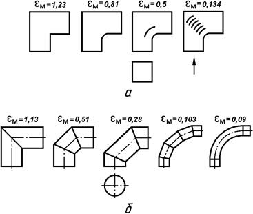
Fig. 3.20. Values of coefficients of local head losses
in swivel knees:
a - square section; b - circular section
Air density, kg / m3:
where t is the air temperature at which the density is determined, ° С.
Here ρ = 353 / (273 + 22) = 1.197 kg / m3 is the air density at a given room temperature; λ = 0.02 for air ducts made of metal pipes; coefficients of local pressure losses are taken: εm1 = 0.5 for louvers at the inlet; εm2 = 1.13 for a round elbow at α = 90 °; εm3 = 0.1 for a sudden expansion of the hole when the ratio of the area of the air ducts in the next section of the network to the area of the air duct in the previous section of the network is equal to 0.7.
Air duct diameters in the third and fourth sections of the network:
d3 = d4 = d1 / 0.7 = 0.28 / 0.7 = 0.4 m.
Air velocities in air ducts in the third and fourth sections of the network:
where L3 is the amount of air passing in 1 hour through the air ducts of the third and fourth sections of the ventilation network (L3 = L4 = 2 L1 = 4980 m3 / h).
Resistance to air movement in the third and fourth sections of the exhaust ventilation hydraulic network:
Air duct diameter in the fifth section of the ventilation network:
d5 = d4 / 0.7 = 0.4 / 0.7 = 0.57 m.
From a standardized series of values, we take d5 = 0.56 m.
Air velocity in the pipeline of the fifth section:
where L5 is the amount of air passing in 1 hour through the air ducts of the fifth section of the ventilation network (L5 = Ltot = 9960 m3 / h).
Resistance to air movement in the fifth section of the exhaust ventilation:
where εm4 is the coefficient of local pressure losses for the fan diffuser (taken equal to εm4 = 0.15).
Total resistance of the network air ducts, Pa:
Next, we calculate the fan performance, taking into account air leaks in the ventilation network:
m3 / h,
where kp is a correction factor for the calculated amount of air (when using steel, plastic and asbestos-cement pipelines up to 50 m long, kp = 1.1, in other cases kp = 1.15).
According to the required performance and the total design pressure, fans are selected for exchange and local ventilation systems. At the same time, the type, number and technical characteristics of the fans are assigned (Table 3.129), as well as their design: usual - for moving non-aggressive media with a temperature not exceeding 423 K, not containing sticky substances, with a concentration of dust and other solid impurities not exceeding 150 mg / m3; anti-corrosion - for moving aggressive media; explosive - for moving explosive mixtures; dust - for moving air with a dust content of more than 150 mg / m3.
Table 3.129 - Technical characteristics of centrifugal
fans of the Ts4-70 series
| Fan number | Wheel diameter, mm | Flow rate, thousand m3 / h | Enclosed induction motor |
| Brand | Rotation frequency, min-1 | power, kWt | |
| 0,55…6,8 | 4АА63А4УЗ 4АА63В4УЗ 4А80А2УЗ 4А80В2УЗ | 0,25 0,37 1,5 2,2 | |
| 0,95…11,5 | 4A71A6UZ 4A71A4UZ 4A71V4UZ 4A80A4UZ 4A100S2UZ 4A112L2UZ 4A112M2UZ | 0,37 0,55 0,75 1,1 4,0 5,5 7,5 | |
| 2…17,5 | 4A71V6UZ 4A80A6UZ 4A80V4UZ 4A90L4UZ 4A100S4UZ | 0,55 0,75 1,5 2,2 3,0 | |
| 2,5…26 | 4A90L6UZ 4A100L6UZ 4A100L4UZ 4A112M4UZ 4A132S4UZ | 1,5 2,2 4,0 5,5 7,5 |
Fans are selected according to their aerodynamic characteristics (Fig. 3.21). Knowing the performance of the fan, a horizontal straight line is drawn (for example, from the point but
on the ordinate axis at the bottom of the graph at L = 11000 m3 / h) until it intersects the fan number line (point
b
). Then from the point
b
raise the vertical to the intersection with the line of the design pressure, equal to the total pressure loss in the ventilation network (for example, H = 1150 Pa). At the received point
from
determine the fan efficiency η and dimensionless parameter A. In this case, air exchange with the highest efficiency should be ensured.
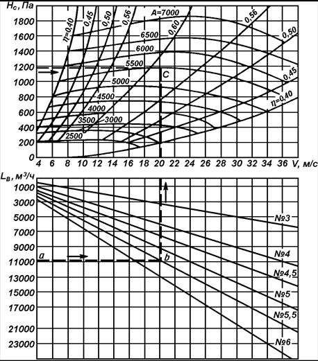
Fig. 3.21. Nomogram for selection of C4 series fans—70
In our case, according to the known Нс and Lв, using Figure 3.21, we select a centrifugal fan of the Ts4-70 series No. 6 of the usual design with an efficiency ηв = 0.59 and a parameter A = 4800.
We calculate the fan speed:
min-1,
where N is the fan number.
Since the rotational speed of the electric motors indicated in Table 3.129 does not coincide with the calculated rotational speed of the fan, we can drive it through a V-belt transmission with an efficiency of ηп = 0.95.
Let us check the fulfillment of the condition for reducing the noise level of the ventilation unit:
π Dv nv = 3.14 0.6 800 = 1507.2 <1800,
where Dw is the diameter of the fan wheel, m.
With the selected fan and its adopted characteristics, this condition is fulfilled.
The power of electric motors for local exhaust and general ventilation systems, kW, is determined by the formula:
where Lw is the required fan capacity, m3 / h;
H is the pressure generated by the fan, Pa (numerically equal to Hc);
ηв - fan efficiency;
ηп - transmission efficiency (fan wheel on the electric motor shaft - ηп = 0.95; flat-belt transmission - ηп = 0.9).
kW.
Select the type of electric motor: for general exchange and local exhaust ventilation systems - explosion-proof or normal version, depending on the removed contamination; for the supply ventilation system - normal design.
The installed power of the electric motor for the exhaust ventilation system is calculated by the formula:
Rust = R · Kz.m = 4.85 · 1.15 = 5.58 kW,
where Kz.m - power factor (Kz.m = 1.15).
Let us assume for the selected fan a 4A112M4UZ electric motor of normal design with a rotational speed of 1445 min-1 and a power of 5.5 kW (see Table 3.129).