The main switchgear - a collector for a warm water floor (TP) is an integral part of the auxiliary or main underfloor heating system. Its design, assembled according to a complete professional scheme, is rather complicated, since it consists of many interdependent elements. Nevertheless, in many apartments, small private cottages or country houses, the heating system is equipped according to a lightweight scheme. It can contain only a few radiators and two or three TP circuits, which makes it possible to move them into a common cabinet with a simplified manifold (comb). Thus, in most cases, assembling a collector for a warm floor with your own hands is quite feasible. And setting up such a system will not cause any particular difficulties in the future.
Why do you need a collector
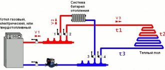
In fact, the collector is a pipe with holes for the inlet and outlet of the coolant, it is also called a distribution and mixing unit. The function of the device is to maintain the required temperature level in the system and control the water flow.
The device is designed to mix the water coming from the boiler, where it is heated, with the cooled liquid coming from the return, to the required level for underfloor heating. Indeed, in a boiler, the coolant usually warms up to +90 degrees, and for a heated floor it is a high temperature.
It requires +40 - 45 degrees, so you can't do without a collector. If water flows directly from the heat source into the circuits, this will lead to overheating of the system and its failure.
In addition, the circuits have different lengths, and they have different heat energy requirements. Therefore, a special unit is needed between the boiler and the pipeline, which will distribute the flows of hot water along the loops.
How to make a choice
When choosing, first pay attention to the number of circuits required for connection. When purchasing a collector for water-based flooring, it is best to purchase a comb with extra headroom for one outlet. It will be needed if it becomes necessary to split a long circuit into two branches or connect additional equipment.
You also need to decide on the type of material. The most reliable devices are made of stainless steel, natural bronze or brass. The best option would be mixing units from renowned manufacturers: Valtec, Stout or Tim.
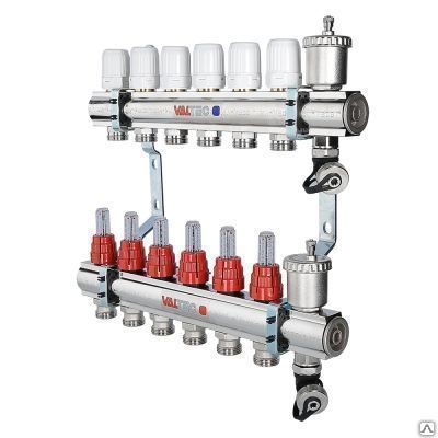
Valtec
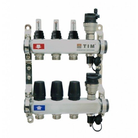
Tim
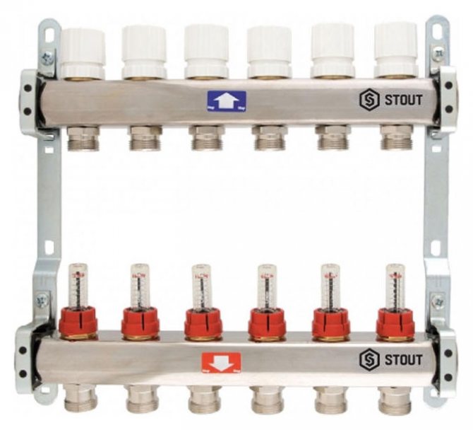
Stout
Types and principle of work
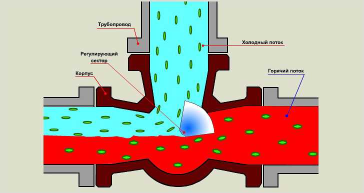
Collector devices differ in the material from which they are made - brass, plastic or stainless steel. And also by the type of valve:
- With two-way - the design feature is continuous heating of the coolant. The heated water is supplied constantly, and the shut-off valves regulate its volume. As a result, the surface heats up evenly, while overheating of the system is not possible. But this model is not suitable for rooms with an area of more than 200 m2.
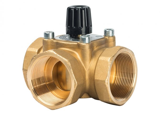
- With three-way - universal equipment, recommended for large rooms. The technology allows installation with a servo drive and various automation. The valve is capable of creating optimal operating pressure, adjusting the temperature level and the amount of the supplied coolant.
Views
In addition, there are 4 types of collectors:
- Simple - a pipe with shut-off valves having an internal and external thread. The model is cheap, but there is no function for configuring the system. To install such a collector on warm floors, additional elements are required.
- Equipped with outlets from a valve for regulation, and valves for connecting circuits - a Chinese device. The structure often leaks, but the repair is not difficult, it is enough to change the gasket. The distance between the flow and return pipes does not correspond to European standards, therefore different fixtures are required.
- With control valves and Euro-cones - an expensive model. It does not have ball valves, but there are fittings and adjustment valves, a servo can be installed on them, which will regulate the temperature in the line.
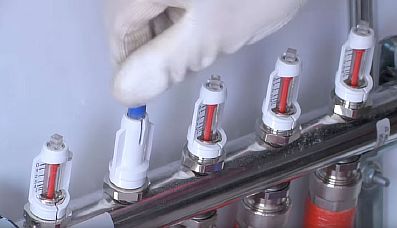
- With flow meters - they are located on the supply pipe of the collector, and sockets for servo drives are located on the back. Such a device is designed for underfloor heating with different lengths of circuits, the presence of flow meters allows you to adjust the volume of the coolant in each circuit.
Any model is equipped with outlets for the release of water and air.
Principle of operation
The general principle of the unit functioning, regardless of the type of valve (two or three-way), is to distribute the water flow along the loops of the heating floor, which circulates under the influence of the pump. The amount of coolant entering each branch is regulated mechanically or automatically - by a servo drive.
The work process looks like this:
- The heat carrier heated to 60 - 80 degrees is supplied from the source to the comb through the thermostatic valve;
- The chilled water flow from the return flow comes from the distributor;
- The shut-off valve has a head that regulates the temperature of the liquid;
- The mixed two streams are fed into a mixing pump, then the water is distributed through the pipelines.
When the degree of heating of the coolant in the line decreases to the required level, heated water from the source is mixed in, a two or three-way valve is responsible for this.
Homemade constructions
The collector has a significant disadvantage - high cost.
Therefore, many "homemade products" assemble with their own hands various options for collectors, in accordance with their wallet and the availability of components.
There are two options for this path:
A 3-loop collector circuit can be implemented as follows:
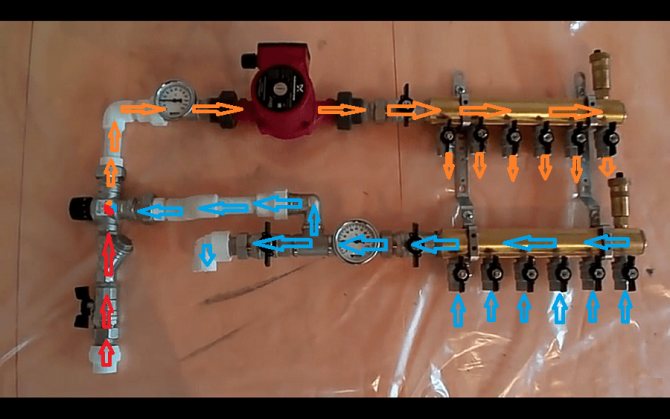
First, collect the collector pipes - the return and the coolant that feeds the heating circuits. To do this, use one comb for 3 channels or 3 single-loop nodes for each collector. The return collector is equipped with a flow sensor or a flow meter and a counter-mounted connection node for the return supply hoses for each loop.
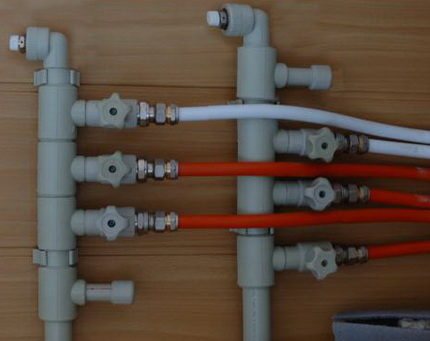
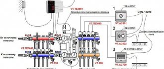
One-loop collectors are connected by threaded elements into a comb. Each coolant loop contains a heat sensor with an actuator and a unit for connecting the heating circuit power supply line. Air vents are connected to one end of the collectors, and on the other, a coolant pump is connected to the collector pipes, and in addition to this point a thermostatic valve or servo drive is connected, which from time to time replenishes the mixer with hot water. The assembled manifold is attached to the wall, tested for functionality and connected to the heating circuits. After that, the final installation and adjustment of the entire system is carried out.
Here is the simplest working version of a collector for a warm floor available to a wide range of homemade craftsmen. The capabilities of real collectors are often expanded by connecting more complex regulation and metering systems.
For example, they connect heat meters, additional temperature meters and much more, who are in a lot - that is why there are self-made inventors in order to "assemble something yourself".
If a self-made collector is soldered from polypropylene pipes, then you need to replenish your arsenal of tools with a special soldering iron for welding parts from this polymer.
When assembling by welding, the size of each single-loop assembly increases due to seams, and if there are more than 3 thermal circuits, then the entire collector becomes cumbersome, and its installation becomes problematic. Otherwise, the scheme of the plastic collector and its setting are no different from those described earlier.
Well, now it's time to finish the article. All the material that I wanted to share has been reviewed. I hope it will be useful to you, and you will use it if you need to install a collector for underfloor heating with your own hands Improve your own practical skills and gain all the new knowledge, as they say: "It's never too late to learn!" That's all, thanks for your attention, successful and easy repair!
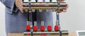
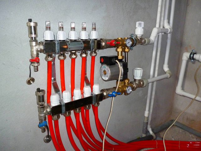
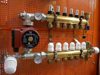
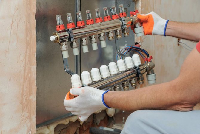
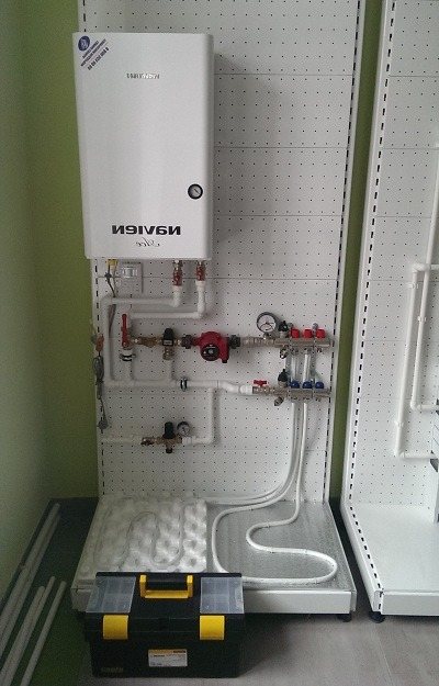
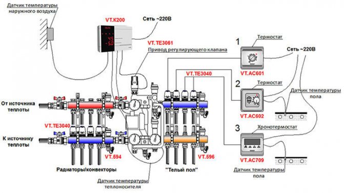
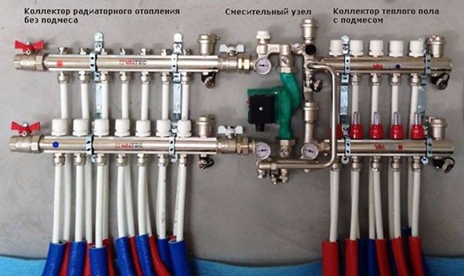
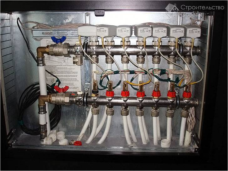
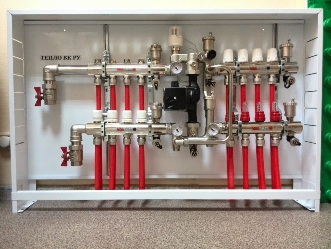
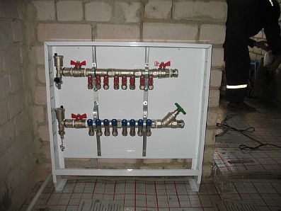
Manifold cabinet device
A manifold cabinet is a structure that includes a pump-mixing unit and a manifold block.
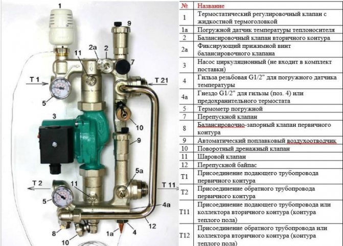
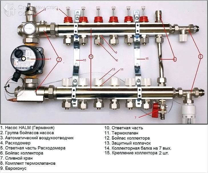
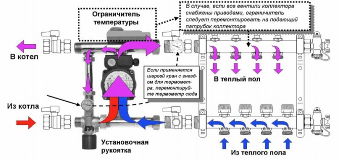
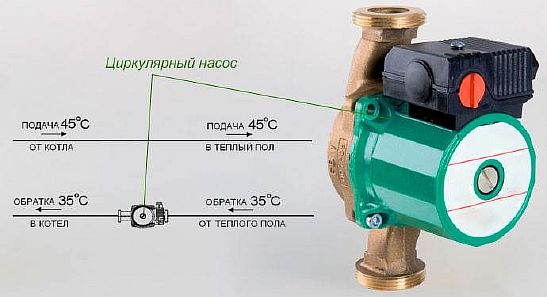
Pump-mixing unit
This unit is designed to dilute the heated water flowing into the water floor line, with the spent, cooled coolant. The impellers of the pump are responsible for the mixing process.
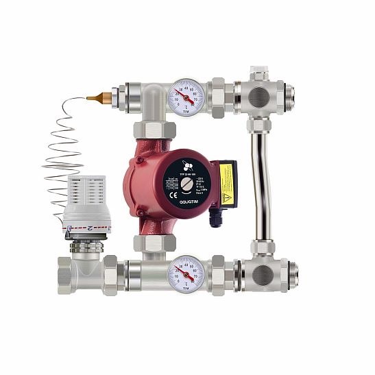
It is the pump that supplies the liquid diluted to the required degree to the system. It, moving through the pipes, gives off heat to the room and the cooling returns to the mixing unit.
The temperature setting is carried out using balancing valves, with their help, the flow of waste water in the pipes is also regulated. To heat a small room, the shut-off valves must be opened, if the room is small, close.
This collector circuit for underfloor heating is equipped with a thermal head, which is responsible for the temperature level in the system. It opens or closes the hot water supply plug. When the flow of the coolant stops, the bypass valve opens and the liquid moves through the free bypass.
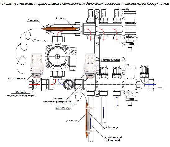
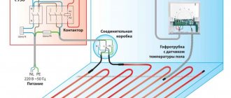
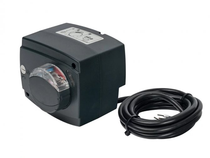
With a simple method of strapping the collector, manual temperature control is done. A servo drive with a thermostat is used to automate the process. The servo drive receives a signal from the thermostat about the temperature level in the room, and based on this indicator, it opens or closes the return manifold flap, thereby regulating the circulation of water in the floor.
The main indicators characterizing the pumping and mixing unit:
- operating pressure - maximum value 10 bar;
- temperature level - +90 degrees (maximum);
- temperature range - from 20 to 60 degrees.
Manifold block
The manifold cabinet is equipped with a block responsible for regulating the water flow, which enters the floor main and returns back.
Technical indicators:
- product diameter - 1 or 1.25 inches;
- number of taps - from 3 to 12;
- pressure (operating value) - 10 bar;
- the maximum level of heating of the coolant is +100 degrees.
In the manifold block there are two rows of bypasses... One, the so-called straight row, is responsible for adjusting the volume of the hot coolant, the other (reverse) regulates the cooled water.
Features of operation
A properly made and wired manifold is fairly easy to operate. Temperature control, supply and distribution of the coolant into the system are carried out automatically. But for preventive purposes, periodic testing of the system is required. Such a procedure consists of the following actions:
- checking the performance of all elements of the switchgear;
- control of the tightness of the connections to prevent leaks during the operation of the system
- clarification of the characteristics of the coolant in each separate branch - the maximum heating temperature, the time spent on heating, speed.
It is also necessary to check the compliance of the temperature regime in the system with the specified parameters.To do this, you need to set a certain temperature and take readings from the thermometers installed in the manifold assembly.
A self-made collector will help to avoid high costs for a heating system. Its assembly must be carried out strictly according to the scheme. If there is no experience in installing heating devices, then it is better to entrust the connection to professionals. High-quality and continuous control of the warm floor can only be carried out with the correct connection of the switchgear and the correct selection of all the components of the manifold assembly.
Correct assembly of the collector for underfloor heating
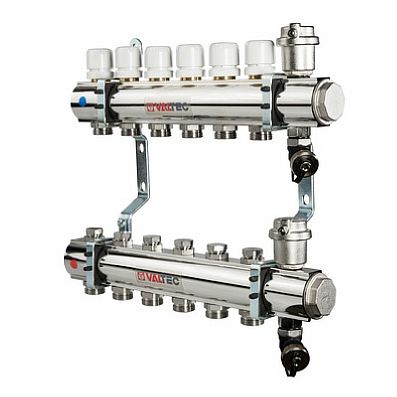
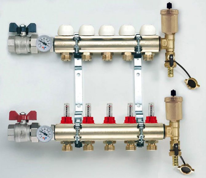
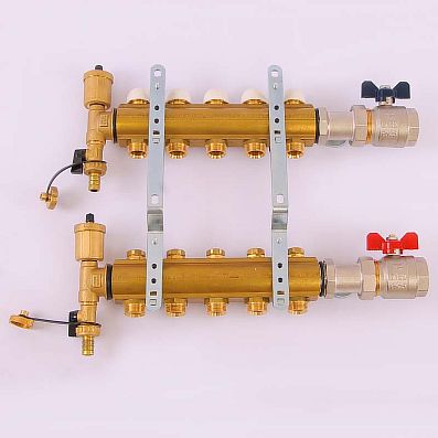
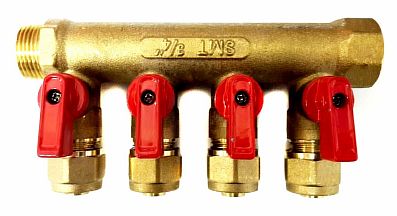
Collecting a purchased factory-made collector is a simple process. Included:
- a distributor with rotameters, it is connected to the supply - it has 2 or more outlets for circuits;
- return manifold with thermal valves instead of flow meters;
- automatic air vents;
- taps with plugs for supplying and draining water from the underfloor heating line;
- inlet and outlet temperature thermometers;
- shut-off ball valves and brackets.
When purchasing the device, its completeness can be changed, starting from the budget and the method of connecting to the boiler. It is permissible to install a distributor without rotameters or 1 thermometer, not 2.
Build process
The factory device is made so that everyone could mount it with their own hands. That is, more often the distribution parts are sold already assembled, only the contours of the underfloor heating need to be connected to them, and parts that are of secondary importance must be connected.
The equipment should be assembled in stages:
- The device is removed from the packaging. In the factory models, the flow and return pipes already have flow meters and valves. If the knot is divided into several parts, then they should be twisted together.
- The collector is fixed on a bracket, this will allow for further assembly with great convenience.
- The rest of the parts are connected - an air vent, valves, plugs and control devices.
- Ball valves are mounted on the return manifold.
The circulation pump and valves must be fixed after fixing the unit to the wall.
Installation process
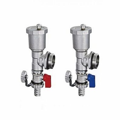
In order to carry out the installation, you must first prepare all the components. For example, VALTEC manifold systems are delivered disassembled. First you need:
- Remove one of the device mounting brackets with a screwdriver.
- Install shut-off valves.
- Screw the automatic air vents onto them.
- Next are the drain valves.
- After that, plugs are put in and the mounting bracket is returned to its place.
DIY collector installation instructions are not particularly difficult:
- To begin with, choose a place so that the length of all heating circuits is approximately the same.
- Next, you should fix the device on the wall so that the manifold cabinet assembly for a warm floor with a pump for pumping liquid fits in it easily, and all adjustments are made quickly and conveniently. Usually this is a box no more than 1x1 m in size and 12 cm thick.
- After fixing, all pipes are connected and the cabinet is assembled.
Tips & Tricks
Before buying a collector, make calculations of the required length of pipes, their position. It would be better to install two 6 6 meters instead of one for 12, which will help to equalize the pressure and temperature in too remote areas. The installation diagram of the collector should provide for its location at a level higher than the warm floor or heating circuit in order for the air to be removed from the pipes correctly in automatic mode.
https://youtube.com/watch?v=JuPDaHfrBL0
| Manufacturer | Cost depending on the number of flow meters, rubles | ||||
| 2 | 3 | 4 | 5 | 6 | |
| Oventrop | 4 100 | 5 150 | 6 100 | 7 000 | 8 100 |
| Watts | 3 550 | 4 650 | 5 700 | 6 750 | 7 800 |
| Kermi | 3 500 | 4 400 | 5 500 | 6 450 | 7 500 |
| Rehau | 8 200 | 9 350 | 10 700 | 12 150 | 13 550 |
| Valtec | — | 6 600 | 7 950 | 9 300 | 10 700 |
| Manufacturer | Price | |||||
| 7 | 8 | 9 | 10 | 11 | 12 | |
| Oventrop | 9 250 | 10 200 | 11 300 | 12 250 | 13 400 | 14 400 |
| Watts | 9 000 | 9 950 | 11 000 | 12 050 | 13 100 | 14 250 |
| Kermi | 8 550 | 9 600 | 10 700 | 11 750 | 12 700 | 13 850 |
| Rehau | 15 250 | 16 900 | 18 350 | 19 800 | 21 450 | 22 550 |
| Valtec | 12 400 | 13 850 | 15 250 | 17 200 | 18 050 | 19 450 |
Based on the data given in the table, we can conclude: the cost of the Kermi collector for the underfloor heating system today is one of the most affordable, despite the fact that it is a high-quality product from a German company, made of stainless steel.
An expensive price category is represented by the young Russian-Italian company Valtec and the German "dinosaur" Rehau. The first, having appeared in 2002, has already managed to enrich its assortment with brass and steel appliances and manifold cabinets. The second, possessing the same assortment, has more than 60 years of experience behind it. That is why Rehau collectors for underfloor heating systems with flow meters occupy the highest price category in the table, because, trusting the professionals, the chances of failure are minimal.
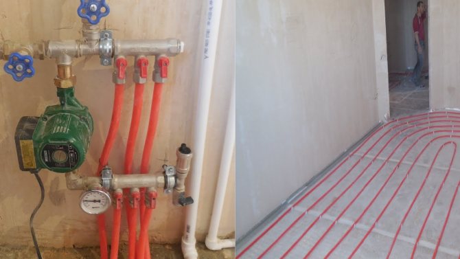
Installation of the underfloor heating collector
Having collected the main elements, you can proceed to the installation and connection of the underfloor heating collector. The process consists of several steps:
- Location and location of installation. The standard height of the collector attachment on the wall from the base of the floor is 500 - 1000 mm, it should not be installed below, since it will be difficult to connect the floor pipes to it. In addition, it should be placed so that the length of all loops is the same, and there should be free access to it, preferably in the middle of the room.
- Installing a manifold cabinet. At the planned site, a collector cabinet is being installed, usually its size is 1 by 1 m, with a wall thickness of 12 cm. It can be placed in an equipped niche or fixed directly on the wall. The surface of the wall must be flat, otherwise the structure may malfunction.
- Fastening the comb in the box. The cabinet is equipped with special guides, they can be moved to the required distance, it depends on the length of the collector. They have fasteners - bolts, with the help of which the device is fixed in the box.
- Installation of the pump and valves (two or three-way) is carried out according to the planned scheme. On the supply pipe that goes from the boiler, a valve with a thermal head is first mounted, then the pump is installed on flanges with union nuts, it must be placed between the valve and the manifold. It is impossible to install the pump in front of the shut-off valves, then the valve will not function, and the water will not flow correctly.
Connecting the TP to the collector
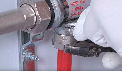
It is necessary to connect the contours of the underfloor heating to the taps of the comb using a threaded connection under the Eurocone. More often, the Eurocone has a diameter of 17 mm, while the floor hose is 16 mm. Therefore, you will need to calibrate it for this size. Then:
- it is necessary to put the union nut on the tube, insert the compression ring and the thrust sleeve;
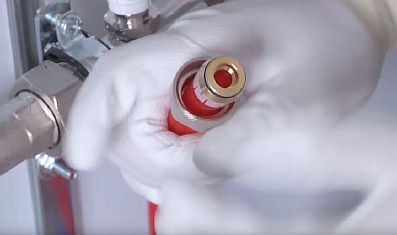
- manually connect the end of the hose to the comb fitting;
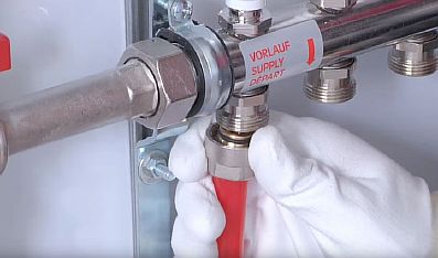
- finally tighten with two wrenches - one fixes the hexagon on the fitting, the other tightens the connection.
Collector setup
The process of setting up a collector for a water underfloor heating is done according to the following instructions:
- removing the cap from the valves;
- fixing the valve with a hexagon;
- determination of the number of revolutions for a specific loop;
- scrolling the valve by the calculated number of times.
The rest of the contours of the underfloor heating can be adjusted as well.
The service life and quality of the floor depends on how accurately the setting is made.
Can a collector be installed below the level of the warm floor - for example, in the basement?
There are times when the distribution and mixing unit has to be installed not on the floor of the warm floor, but below, for example, if the boiler room is in the basement, or you simply do not want to spoil the interior of the apartment.
Such a wiring is permissible, the installation of the collector is carried out in the same sequence as usual. There is only one problem - automatic bleeding of air masses from the line is not possible if the air vent is located on the comb.
Output - installation of an air vent on the return pipe between the comb and the floor hinges, and in front of it, a locking device with a shut-off valve is installed. Access to the air vent is mandatory.
For your information! Since an air vent is required for each branch of the floor, it is worth considering the advisability of installing the collector below the level of the warm floor.
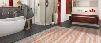
Warm water floor refers to a modern heating system, perfect for furnishing in private houses. With proper installation of the "pie" of the floor and the collector, the structure is able to provide comfortable conditions in the room.