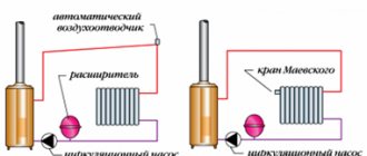
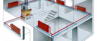
In any heating system consisting of several radiator batteries, their heating temperature depends on the distance to the heating boiler - the closer to it, the higher the degree. Therefore, for its efficient operation and to ensure various requirements for heating the premises, a balancing valve for the heating system is built into the line.
There is a wide range of these control valves on the construction market, which have the same principle of operation and some differences in design. It is useful for any master or owner who independently conducts heating in his private house to know what a balancing valve is for, the rules for installing and adjusting it to ensure the efficiency, economy and functionality of the heating main.
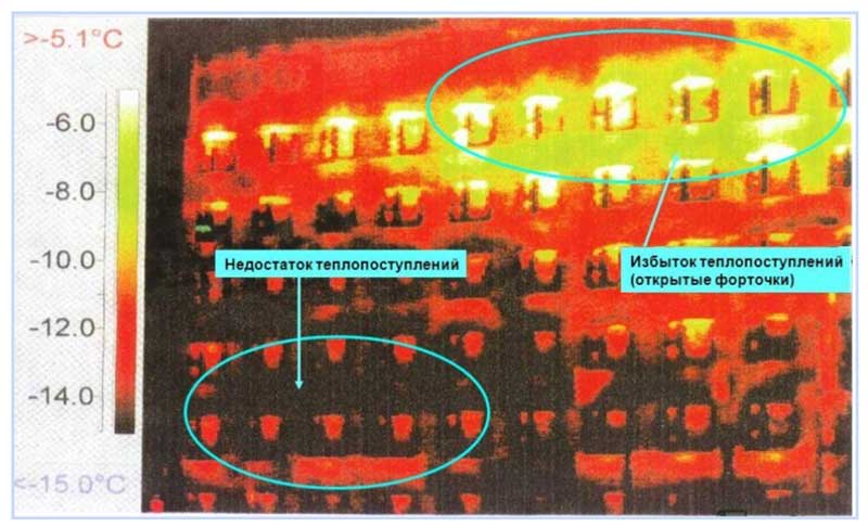
Fig. 1 Thermal imaging of a residential building with unbalanced heating
What is a balancing valve
To maintain the same temperature in the batteries, they are adjusted by changing the water flow - the less coolant passes through the radiator, the lower its temperature. You can shut off the flow with any ball valve, but in this case it will not be possible to set and adjust the same temperature in the devices if the number of heating devices is more than one. It will have to be measured with temperature sensors on the surface of the batteries and by rotating the valve by an experimental method to set its desired position.
Balancing valves commonly used for tuning effectively solve the problem of maintaining balance automatically or by simple calculations of the required flow rate and the corresponding settings in the devices. Structurally, the device partially blocks the flow of the heat carrier, reducing the pipe cross-section similarly to any shut-off valve, with the difference that the required volume of supply is precisely set according to the setting scales using the rotary handle of the mechanism or automatically.


Design
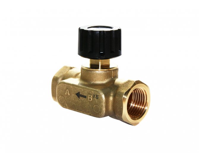
Control valves vary in design. In the classic version, the device is equipped with a straight stem and a flat spool, the adjustment is carried out by changing the flow area between the spool and the seat. The translational movement of the spool is provided by rotating the handle.
Balancers are also available with a rod located at an angle relative to the coolant flow, the spool can have a conical, radial or cylindrical shape, and is actuated by a servo drive.
Balancing valve design
Why use
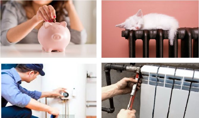
The installation of balancing taps in the heating system, in addition to maintaining the same temperature of the batteries, in an individual house has the following effect:
- Accurate regulation of the coolant temperature allows you to set its value depending on the purpose of the premises - in living rooms it can be higher, in utility rooms, storerooms, workshops, gyms, food storage areas, using balancers, you can set it to a lower value. This factor increases the comfort of living in the house.
- Changing the coolant flow using a balance valve regulator, depending on the purpose of the premises, brings a significant economic effect, allowing you to save on fuel.
- In winter, in the absence of owners, constant heating of the home is necessary - using balancing valves, you can achieve a heating system setting with minimal fuel consumption and maintaining a constant temperature in all rooms. This advantage also saves the owners' financial resources.
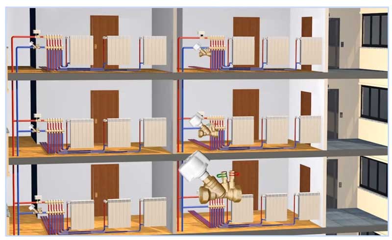
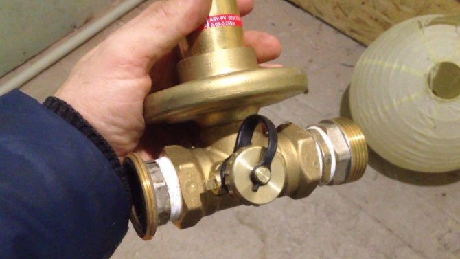
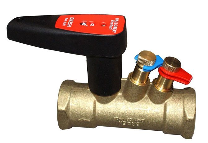
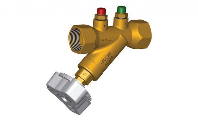
Fig.3 Manual balancing valves for heating and hot water (DHW) systems in the home
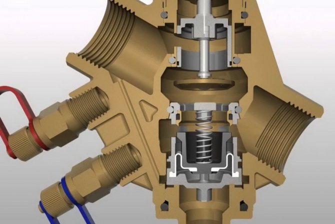
Principle of operation
Turning the adjusting knob changes the position of the valve spool. As a result, the size of the section between it and the saddle changes.
Thus, the coolant, passing through a large or small section of the valve, changes its pressure, since the throughput changes. Thus, by adjusting the pressure, you can achieve an even distribution of heat for each heating device.
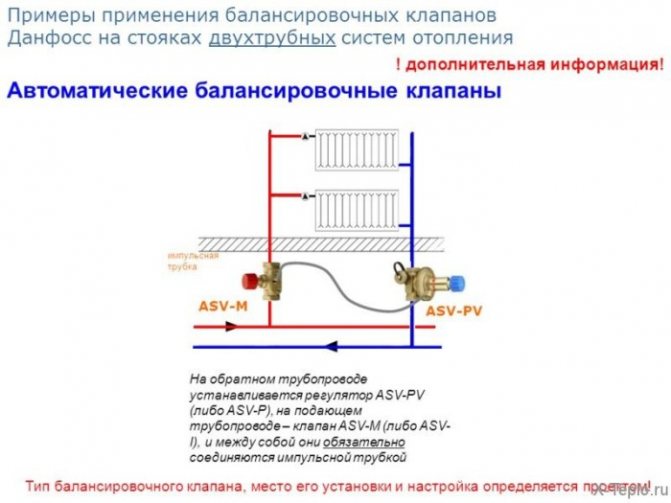
For automatic regulation of heat distribution, two balancing valves are installed in the system - on the inlet circuit and in the return. They are interconnected. The balancing effect of the system will take place automatically.
But for this it will be necessary at the very beginning, at the first start, to correctly adjust and adjust the entire heating system. If all the manufacturer's requirements are met, the balancing equipment works flawlessly.
Please note: some mistakenly, on the advice of local "Kulibins", try to install a ball valve instead of a balancing valve. The absurdity of such an idea becomes apparent immediately after the launch of the system. The valve does not belong to the control valve from any side.
Design and principle of operation
The principle of operation of the balancing valve consists in shutting off the fluid flow with a sliding valve or a stem, which causes a decrease in the cross-section of the flow channel. The devices have a different design and connection technology; in the heating system, they can additionally:
- Maintain the differential pressure at the same level.
- Limit the flow rate of the coolant.
- Shut off the pipeline.
- Serve as a drain for the working fluid.
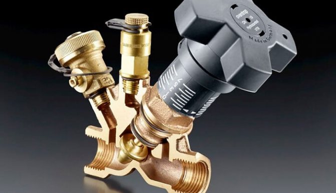
Structurally, balancing valves resemble conventional valves, their main elements are:
- Brass body with two internal or external threaded ports for connection to standard pipe diameters. Connection in the pipeline in the absence of a threaded fitting with a movable threaded nut (American) is made through its analogs - additional transition couplings with different union nuts.
- A locking mechanism, the movement of which regulates the degree of overlap of the channel for the passage of the heat carrier.
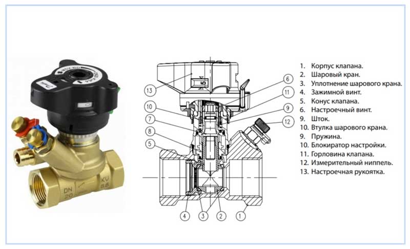
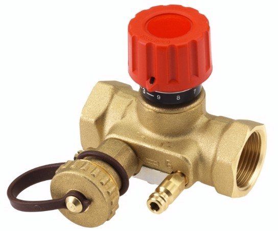
Fig. 4 Danfoss LENO MSV-B manual balancing valve device
- Adjustment knob with scale and setting indicators to regulate the flow inside the instrument.
- Modern models are equipped with additional elements in the form of two measuring nipples, with the help of which the flow volumes (throughput) are measured at the inlet and outlet of the device.
- Some models are equipped with a shut-off ball mechanism to completely shut off the flow, or have a function to drain the liquid from the water supply.
- High-tech modern types can be controlled automatically, for this, instead of a rotary head, a servo drive is installed, which, when supplied with electricity, pushes the locking mechanism, while the degree of channel closure depends on the magnitude of the applied voltage.
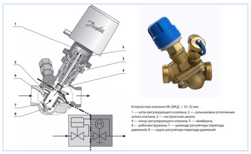
Fig. 5 Automatic balancers Danphos AB-QM - design
Installation and operation
The balancing valve is installed according to the manufacturer's requirements. If there is an arrow on the body, the device is mounted in such a way that the direction of the arrow coincides with the direction of flow of the transported medium so that the valve can create a design resistance. Some manufacturers produce balancing valves that can be installed in any direction. The spatial arrangement of the stem in most cases is not important.
To prevent the valve from failing due to mechanical damage, a branded filter or a standard mud collector is installed in front of it. To eliminate unwanted turbulence, valves are recommended to be installed on straight pipeline sections, the minimum length of which is indicated in the manufacturer's instructions.
If the heating system is equipped with automatic valves, it should be filled through special filling fittings installed next to the valves on the return pipe, while the balancing valves on the supply pipe are closed.
Adjustment of the balancing valve is carried out using a table with indicators of pressure drop and flow rate of the heating medium (attached to the device) or using a flow meter for balancing. But the initial calculation of the flow rate and operational parameters must be performed at the design stage of the heating system.
Assembled balancing valve design
Types of balancing valves
Balancing in heating systems is carried out using two types of control valves:
- Manual... The design is a body made of non-ferrous metals (bronze, brass), in which a balancing element is placed, the degree of extension of which is set by turning a mechanical handle.
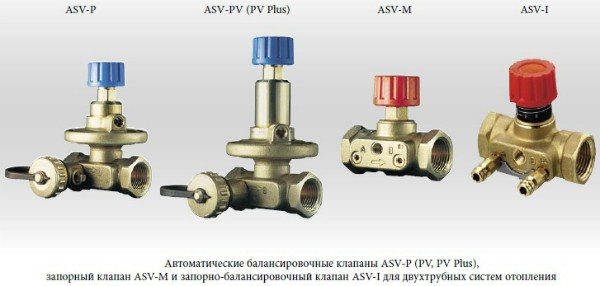
- Automatic... Automatic devices are installed on the return pipeline together with valves of partners who are able to limit the flow of the medium by presetting the throughput. When connected, they are connected to partners via an impulse tube that connects to the built-in test nipple. If the valve is installed to supply water in a straight line, its handle is red, when installed in the return line, it is blue (Danfoss models). Automatic types are models controlled by a servo drive, which is supplied with constant voltage.
In this article, you will understand what this device is for and how to put it into practice. Let's consider the schemes. The principle of operation of the manual and automatic valve.
Balancing valve
Is a device or type of plumbing fittings designed to regulate the cross-section to pass a liquid of a given flow rate. But do not assume that this consumption will be constant. It will change depending on the differential pressure difference across the Balancing Valve. That is, the larger it is, the higher the flow rate.
For automatic balancing valves, a flow stabilization is achieved with a certain pattern. We'll talk about them below.
In order to regulate the flow in automatic mode, you should install special “flow controllers”.
In other words. The balancing valve is designed to regulate the local hydraulic resistance.
Seen through the eyes of a hydraulic specialist, this device regulates the local hydraulic resistance. That is, how does it happen? It happens like this: The usual regulation is an increase or decrease in the cross-section through the valve. Thus, this section creates hydraulic resistance and if the section is reduced, the hydraulic resistance will increase. And if the cross section is increased, then the hydraulic resistance will decrease. With a decrease in the cross section, the flow rate decreases.
Usually this is a simple, non-whimsical mechanical device. Serves smoothly.
There are different modifications of balancing valves.
What is the difference between a balancing valve and a conventional tap?
If you feel sorry for the money for the balancing valve, then you can use a conventional valve to adjust the flotation. But the balancing valve differs in that it can be done on it, a smoother adjustment of the flow area. And with an ordinary tap, you can make adjustments, but it will turn out to be coarser and not accurate. It all depends on the accuracy you want. You can, for example, buy a ball valve with a long lever switch and also try to adjust by bringing the lever to a different degree of rotation. The balancing valve also has special inputs that make it possible to measure the flow rate.
Did you know that the return flow valve for the radiator system is used to adjust the hydraulic resistance. This valve can be called a balancing valve!
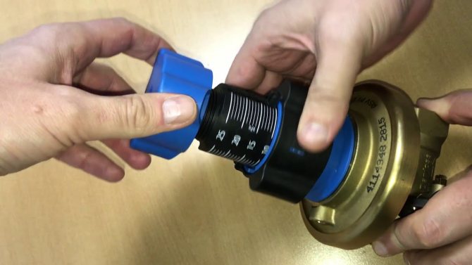
If you look at the image, you can see some other "bombs" 
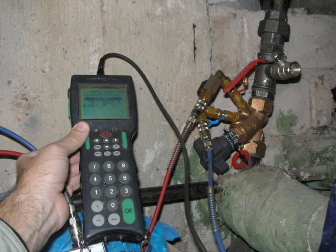
These gadgets (Fittings for measurements or all kinds of connecting threads) are needed in order to connect a special device that makes it possible to take measurements.
Example:
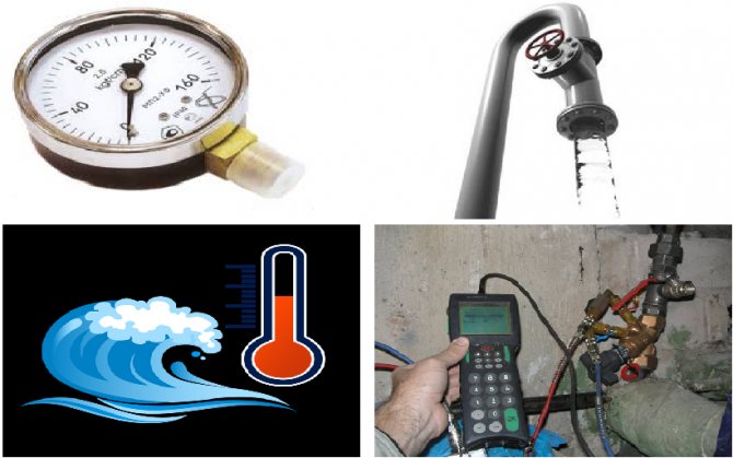
Measuring device PFM 3000
designed to measure differential pressure, flow rate and temperature, as well as for hydraulic balancing of heat and cooling systems. The PFM 3000 is lightweight and compact. This is achieved due to the compact placement of pressure sensors inside the device body. The shockproof and waterproof housing protects the sensors from environmental influences and allows the PFM 3000 to be used in harsh climatic conditions. The included adapters allow the PFM 3000 to be connected to any type of nipple. The set of the device includes: a digital thermometer, a cable for connecting the device to a computer (USB), and a CD with software. These options allow the PFM 3000 to be used for hydraulic balancing of heating and cooling systems of any branching.
Automatic balancing valve
Automatic balancing valves are used to maintain a constant pressure difference between the supply and return pipelines of controlled systems, to ensure a constant flow rate or stabilize the temperature of the medium transported through the pipeline. For example:
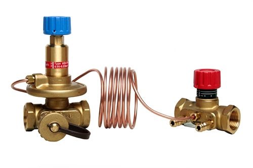
Danfoss ASV series automatic balancing valves are used to provide automatic hydraulic balancing of heating and cooling systems. Automatic balancing of the system is the maintenance of a constant differential pressure when the load (and, accordingly, the flow rate) changes from 0 to 100%. The use of ASV series valves avoids the complexities of commissioning the system, only the valves need to be installed. Automatic balancing of the system under any load provides significant energy savings.
The ASV-PV valve is installed in the return pipe together with a partner valve in the supply pipe.
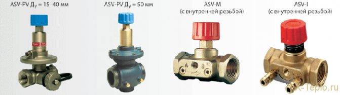
We recommend using ASV-M / ASV-I valves for sizes DN 15 to DN 50 and MSV-F2 valves for sizes DN 65 to DN 100 as partners.
What is the pressure drop between two points?
Consider an example: Suppose we have pressure gauges on the supply and return pipelines, which show the pressure at these points. The difference will be the value that is equal to the difference between the two gauges. That is, if the pressure gauge shows 1.5 Bar, and the other 1.6 Bar, then the difference is 0.1 Bar.
Therefore, the automatic balancing valve stabilizes this difference between the two points. The automatic balancing valve is always paired, since it is necessary to be able to feel these differences at two points.
Why was this valve called balancing?
To understand this, let's find out what balance is!
Balance
- This is a quantitative ratio, consisting of two parts, which must be equal to each other, since they represent the receipt and expenditure of the same amount.
That is, if you have a branch line in the pipeline, and some of them have a large flow rate, and another small, then in this case a balancing valve is needed to pressurize the liquid passage, on the pipeline with a high flow rate in order to level these costs.
For example:
The balancing valve can be omitted where there is a small flow rate along the circuit. That is, a balancing valve is needed in order to create resistance on any circuit in order to equalize the flows.
Balancing valve theoretical graph. (The differential created on the valve itself is the differential created at the inlet and outlet of the balancing valve).
To understand this graph, let's take a look at the diagram:
The difference is equal to M1-M2. The difference is equal to the difference between the gauges.
If we smoothly increase the pump power, we get the following graph:
Now let's take a look at the graph for an automatic balancing valve:
In this diagram, the radiator is represented as a load. It is possible to put a distribution manifold with many circuits in place of the radiator.
Schedule:
The graph shows that the outlet head becomes stabilized if the pump head reaches or exceeds the stabilizing threshold.
So what happens? It turns out that we get the ideal head stabilization for our circuits.
What does the stabilization of the head give us? It makes it possible to have a constant flow rate, which does not depend on the power drops of the pumps. That is, the automatic balancing valve does not allow the excess of the pressure drop, thereby preventing the overrun of the coolant. Also, with a stable constant pressure, a constantly unchanging flow rate of the coolant occurs. But only under conditions if your circuit has a constant hydraulic resistance. If your heating circuit has a dynamically changing hydraulic resistance, then the flow rate will also be unstable. With a dynamic changing pressure drop, you can at least limit the overflow of the circuit.
It is also possible to stabilize the differential pressure with the Overflow Valves.
For those who want to understand in more detail about the hydraulic resistance of valves and pressure, I recommend that you familiarize yourself with my personally developed section on hydraulics and heat engineering. There you will find useful hydraulic and thermal calculations. After studying my articles on Hydraulics and Heat Engineering, you will definitely learn how to understand how to make a hydraulic calculation of water supply and heating.
| Like |
| Share this |
| Comments (1) (+) [Read / Add] |
All about the country house Water supply Training course. Automatic water supply with your own hands. For Dummies. Malfunctions of the downhole automatic water supply system. Water supply wells Well repair? Find out if you need it! Where to drill a well - outside or inside? In what cases well cleaning does not make sense Why pumps get stuck in the wells and how to prevent it Laying the pipeline from the well to the house 100% Protection of the pump from dry running Heating Training course. Do-it-yourself water-heating floor. For Dummies. Warm water floor under a laminate Educational video course: On HYDRAULIC AND HEAT CALCULATIONS Water heating Types of heating Heating systems Heating equipment, heating batteries System of underfloor heating Personal article of underfloor heating Principle of operation and scheme of operation of underfloor heating Design and installation of underfloor heating materials for underfloor heating Water underfloor heating installation technology Underfloor heating system Installation step and methods of underfloor heating Types of water underfloor heating All about heat carriers Antifreeze or water? Types of heat carriers (antifreeze for heating) Antifreeze for heating How to properly dilute antifreeze for a heating system? Detection and consequences of coolant leaks How to choose the right heating boiler Heat pump Features of a heat pump Heat pump operating principle About heating radiators Ways of connecting radiators.Properties and parameters. How to calculate the number of radiator sections? Calculation of heat power and the number of radiators Types of radiators and their features Autonomous water supply Autonomous water supply scheme Well device Do-it-yourself well cleaning Plumber's experience Connecting a washing machine Useful materials Water pressure reducer Hydroaccumulator. Principle of operation, purpose and setting. Automatic air release valve Balancing valve Bypass valve Three-way valve Three-way valve with ESBE servo drive Thermostat to the radiator Servo drive is collector. Choice and rules of connection. Types of water filters. How to choose a water filter for water. Reverse osmosis Sump filter Check valve Safety valve Mixing unit. Principle of operation. Purpose and calculations. Calculation of the mixing unit CombiMix Hydrostrelka. Principle of operation, purpose and calculations. Accumulative indirect heating boiler. Principle of operation. Calculation of a plate heat exchanger Recommendations for the selection of PHE in the design of heat supply objects Contamination of heat exchangers Water heater for indirect water heating Magnetic filter - protection against scale Infrared heaters Radiators. Properties and types of heating devices. Types of pipes and their properties Indispensable plumbing tools Interesting stories A terrible tale about a black installer Water purification technologies How to choose a filter for water purification Thinking about sewage Sewage treatment facilities of a rural house Tips for plumbing How to evaluate the quality of your heating and plumbing system? Professional recommendations How to choose a pump for a well How to properly equip a well Water supply to a vegetable garden How to choose a water heater Example of equipment installation for a well Recommendations for a complete set and installation of submersible pumps What type of water supply accumulator to choose? The water cycle in the apartment, the drain pipe Bleeding air from the heating system Hydraulics and heating technology Introduction What is hydraulic calculation? Physical properties of liquids Hydrostatic pressure Let's talk about resistances to the passage of liquid in pipes Modes of fluid movement (laminar and turbulent) Hydraulic calculation for pressure loss or how to calculate pressure losses in a pipe Local hydraulic resistance Professional calculation of pipe diameter using formulas for water supply How to choose a pump according to technical parameters Professional calculation of water heating systems. Calculation of heat loss in the water circuit. Hydraulic losses in a corrugated pipe Heat engineering. Author's speech. Introduction Heat transfer processes T conductivity of materials and heat loss through the wall How do we lose heat with ordinary air? Heat radiation laws. Radiant warmth. Heat radiation laws. Page 2. Heat loss through the window Factors of heat loss at home Start your own business in the field of water supply and heating systems Question on the calculation of hydraulics Water heating constructor Diameter of pipelines, flow rate and flow rate of the coolant. We calculate the diameter of the pipe for heating Calculation of heat loss through the radiator Power of the heating radiator Calculation of the power of the radiators. Standards EN 442 and DIN 4704 Calculation of heat loss through building envelopes Find heat loss through the attic and find out the temperature in the attic Select a circulation pump for heating Transfer of heat energy through pipes Calculation of hydraulic resistance in the heating system Distribution of flow and heat through pipes. Absolute circuits. Calculation of a complex associated heating system Calculation of heating. Popular myth Calculation of heating of one branch along the length and CCM Calculation of heating. Selection of pump and diameters Calculation of heating. Two-pipe dead-end Heating calculation. One-pipe sequential Heating calculation. Double-pipe passing Calculation of natural circulation.Gravitational pressure Water hammer calculation How much heat is generated by pipes? We assemble a boiler room from A to Z ... Heating system calculation Online calculator Program for calculating Heat loss of a room Hydraulic calculation of pipelines History and capabilities of the program - introduction How to calculate one branch in the program Calculation of the CCM angle of the outlet Calculation of CCM of heating and water supply systems Branching of the pipeline - calculation How to calculate in the program one-pipe heating system How to calculate a two-pipe heating system in the program How to calculate the flow rate of a radiator in a heating system in the program Recalculating the power of radiators How to calculate a two-pipe associated heating system in the program. Tichelman loop Calculation of a hydraulic separator (hydraulic arrow) in the program Calculation of a combined circuit of heating and water supply systems Calculation of heat loss through enclosing structures Hydraulic losses in a corrugated pipe Hydraulic calculation in three-dimensional space Interface and control in the program Three laws / factors for the selection of diameters and pumps Calculation of water supply with self-priming pump Calculation of diameters from central water supply Calculation of water supply of a private house Calculation of a hydraulic arrow and a collector Calculation of a hydraulic arrow with many connections Calculation of two boilers in a heating system Calculation of a one-pipe heating system Calculation of a two-pipe heating system Calculation of a Tichelman loop Calculation of a two-pipe radial wiring Calculation of a two-pipe vertical heating system Calculation of a single-pipe vertical heating system Calculation of a warm water floor and mixing units Recirculation of hot water supply Balancing adjustment of radiators Calculation of heating with natural circulation Radial wiring of the heating system Tichelman loop - two-pipe associated Hydraulic calculation of two boilers with a hydraulic arrow Heating system (not Standard) - Another piping scheme Hydraulic calculation of multi-pipe hydraulic arrows Radiator mixed heating system - passing from dead ends Thermoregulation of heating systems Pipeline branching - calculation of a hydraulic pipeline branching Calculation of the pump for water supply Calculation of the contours of a warm water floor Hydraulic calculation of heating. One-pipe system Hydraulic calculation of heating. Two-pipe dead-end Budgetary version of a one-pipe heating system of a private house Calculation of a throttle washer What is a CCM? Calculation of the gravitational heating system Constructor of technical problems Pipe extension SNiP GOST requirements Requirements for the boiler room Question to the plumber Useful links plumber - Plumber - ANSWERS !!! Housing and communal problems Installation works: Projects, diagrams, drawings, photos, descriptions. If you are tired of reading, you can watch a useful video collection on water supply and heating systems
Balancing valve for heating system
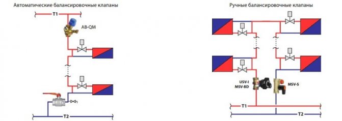
The existing heat supply systems are conventionally divided into two types:
- Dynamic. They have conditionally constant or variable hydraulic characteristics, these include heating lines with two-way control valves. These systems are equipped with automatic differential balancing regulators.
- Static. They have constant hydraulic parameters, include lines with or without three-way control valves, the system is equipped with a static manual balancing valve.
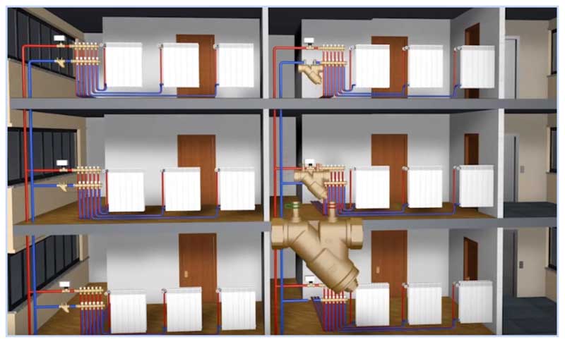
Fig. 7 Balancing valve in line - installation diagram of automatic fittings
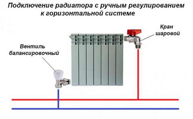
In a private house
A balance valve in a private house is installed on each radiator, the outlet pipes of each of them must have union nuts or another type of threaded connection.The use of automatic systems does not require adjustment - when using a two-valve design, the supply of coolant to radiators installed at a great distance from the boiler is automatically increased.
This is due to the transfer of water to the actuators through the impulse pipe under a lower pressure than the first batteries from the boiler. The use of another type of combination valves also does not require the calculation of heat transfer using special tables and measurements; the devices have built-in regulating elements, which are moved by means of an electric drive.
If a manual balancer is used, it must be adjusted using measuring equipment.
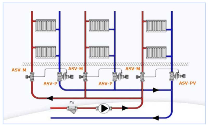
Fig. 8 Automatic balancing valve in the heating system - connection diagram
To determine the volume of water supply to each radiator and, accordingly, balancing, an electronic contact thermometer is used, with which the temperature of all heating radiators is measured. The average delivery volume for each heater is determined by dividing the total by the number of heating elements. The largest flow of hot water should go to the farthest radiator, a smaller amount - to the element closest to the boiler. When carrying out adjustment work with a manual mechanical device, proceed as follows:
- All control valves are opened all the way and water is connected, the maximum surface temperature of the radiators is 70 - 80 degrees.
- A contact thermometer is used to measure the temperature of all batteries and record the readings.
- Since the farthest elements must be supplied with the maximum amount of heating medium, they are not subject to further regulation. Each valve has a different number of revolutions and its own individual settings, so it is easiest to calculate the required number of revolutions using the simplest school rules based on the linear dependence of the radiator temperature on the volume of the heat carrier passing through.
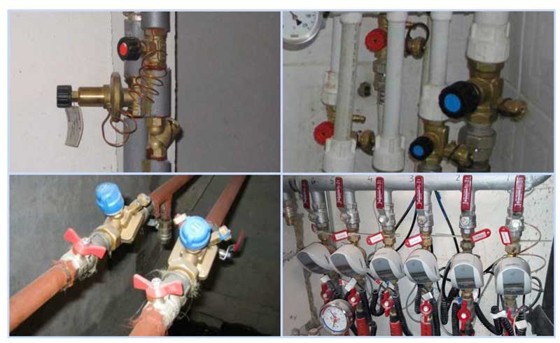
Fig. 9 Balancing valves - installation examples
- For example, if the operating temperature of the first radiator from the boiler is +80 С. will go less, and the resulting volume will be 0.435 cubic meters / h. If all the valves are set not to the maximum flow, but to set the average indicator, then the heaters located in the middle of the line can be taken as a reference point and in the same way reduce the throughput closer to the boiler and increase it at the farthest points.
In a multi-storey building or building
The installation of valves in a multi-storey building is carried out in the return line of each riser, with a large distance of the electric pump, the pressure in each of them should be approximately the same - in this case, the flow rate for each riser is considered equal.
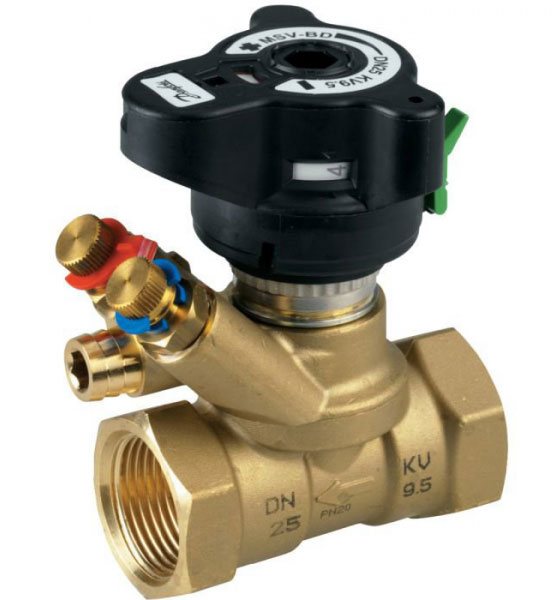
For setting in an apartment building with a large number of risers, it uses data on the volume of water supplied by an electric pump, which is divided by the number of risers. The obtained value in cubic meters per hour (for Danfoss LENO MSV-B valve) is set on the digital scale of the device by rotating the handle.
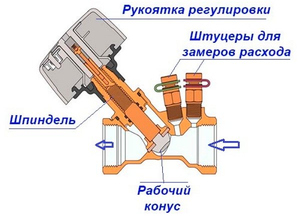
How does a balance valve work?
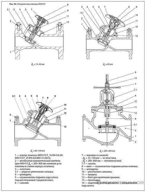
The design of the radiator element, which serves for manual balancing of heating branches, consists of the following parts:
- Brass body with threaded nozzles for connecting pipes. With the help of casting, a so-called saddle is made inside, which is a round vertical channel, which slightly expands upward.
- A shut-off and regulating spindle, the working part of which has the form of a cone, which enters the seat during twisting, thereby limiting the flow of water.
- O-rings made of EPDM rubber.
- Protective cap made of plastic or metal.
All well-known manufacturers have two types of products - angular and straight. Only the form has been changed, but the principle of operation is the same.
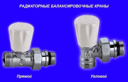
How a valve works in a heating system: During the rotation of the spindle, the flow area decreases or increases, due to which the adjustment is carried out. The number of revolutions, from closed to open, to the limit level, varies from three to five revolutions, depending on who is the manufacturer of the product. To turn the stem, a regular or special hex key is used.
Compared to radiator valves, trunk valves have a different size, inclined spindle position, excellent fittings, which are necessary for:
- to drain the coolant if necessary
- connection of metering and control devices;
- connecting the capillary tube from the pressure regulator.
It should also be mentioned that not every system needs balancing as such. For example, 2-3 short dead-end lines, equipped with 2 radiators on each, can immediately enter the normal operating mode provided that the diameter of the pipes is selected accurately and the distances between the devices are not very large. Now let's look at 2 situations:
- From the boiler there are 2-4 heating branches of unequal length, the number of radiators on each is from 4 to 10.
- The same, only the radiators are equipped with thermostatic valves.
Since the bulk of the coolant always flows along the path with the lowest hydraulic resistance, in the first case, most of the heat will be received by the first radiators that are closest to the boiler. If the coolant flows to these batteries, it is not limited, then the batteries standing at the very end of the batteries will receive the least amount of thermal energy, and thus the difference between the temperature regimes will be from 10 ° C or more.
In order for the farthest batteries to be provided with the required amount of coolant, balancing valves are installed on the connections to the nearest radiators from the boiler. By partially blocking the inner section of the pipes, they limit the flow of water, thereby increasing the hydraulic resistance of this section. In a similar way, the feed is regulated in systems where there are 5 or more dead-end branches.
In the second case, the situation is somewhat more complicated. Installation of radiator thermostats makes it possible to change the water flow automatically if necessary. On extended branches with a large number of heating devices that are equipped with thermostats, balancing valves are combined with automatic differential pressure regulators.
The latter, with the help of a capillary tube, are connected to the balance valve, react to a decrease in whether an increase in the flow rate of the coolant in the system and maintain the pressure in the return at the required level. Thus, the coolant is evenly distributed among the consumers, despite the fact that the thermostats are triggered.
Valve installation
When installing the valve, place it in the direction of the arrow on the body, which indicates the direction of movement of the fluid, to combat turbulence that affects the accuracy of the settings. Select straight sections of the pipeline with a length of 5 diameters of the device and its location point and two diameters after the valve. The equipment is installed in the reverse branch of the system, a plumbing adjustable wrench is enough to carry out the work, the installation is carried out in the following sequence:
- Before installation, be sure to flush and clean the pipeline system to get rid of possible metal chips and other foreign objects.
- Many devices have a removable head; for ease of installation in pipes, it should be removed in accordance with the instructions.
- For installation, you can use linen fiber with an appropriate lubricant, which is wound around the end of the pipe and the outlet of the battery.
- The regulating valve is screwed onto the pipe with one end, the second is connected to the radiator with special washers (American adapter coupling), which is placed on the outlet radiator fitting or screwed into the valve, playing the role of a coupling.
How to adjust the balance of the radiator network
Each valve comes with an instruction manual when you buy it, which contains information on how to calculate the number of handle turns.
Using the attached diagram, you can permanently adjust the energy consumption, saving on heating.
According to the instructions, you need to turn the valve to a certain level.
There are two ways to adjust the valve.
Method 1
Experienced technicians have a simple and proven way to adjust the system.
They divide the valve speed by the number of radiators located around the entire perimeter of the room. It is this method that allows them to accurately determine the flow rate adjustment step. The principle is to close all the taps in the reverse order - from the last to the first radiator.
For a more illustrative example, let's take the following characteristics of the system.
The dead-end system has 5 batteries, which are equipped with manual valves. The spindle in them is adjustable by 4.5 turns. Divide 4.5 by 5 (the number of radiators). The result is a step of 0.9 revolutions.
We recommend that you familiarize yourself with: Low pressure polyethylene pipes - HDPE
This means that the following valves must open the following number of revolutions:
| First balancing valve | by 0.9 turns. |
| Second balancing valve | 1.8 turns. |
| Third balancing valve | 2.7 revolutions. |
| Fourth | 3.6 turns. |
Method 2
There is another, very effective way to adjust. It is carried out faster, and includes the ability to take into account the individual features of each of the radiators. But to carry out such a setting, you will need a special contact-type thermometer.
The whole process proceeds in the following sequence:
- Open all valves without exception and let the system reach an operating temperature of 80 degrees.
- Measure the temperature of all batteries with a thermometer.
- Eliminate the difference by closing the first and middle taps. In this case, the latter mechanisms do not need to be regulated. As a rule, the first valve is turned by a maximum of 1.5 turns, and the middle ones by 2.5.
- Do not make any adjustments for 20 minutes. After adapting the system, measure again.
The main task of this method, like the previous one, is to eliminate the difference in temperature with which all batteries in the room are heated.
Balance Valve Setting
To balance heating in a private house, manual devices of the required diameter are selected, making their selection and adjustment using the appropriate diagram attached in the passport. The initial data for working with the graph are the delivery volume, expressed in cubic meters per hour or liters per second, and the pressure drop, measured in bars, atmospheres or Pascals.
For example, when determining the position of the adjustment indicator of the MSV-F2 modification with a nominal diameter of DN equal to 65 mm. at a flow rate of 16 cubic meters / h. and a pressure drop of 5 kPa. (Fig. 11) on the graph, the points on the corresponding scales of flow and pressure are connected and the line is extended until the conditional scale crosses the coefficient Ku.
From a point on the scale Ku draws a horizontal line for a diameter D equal to 65 mm., Find the setting with the number 7, which is set on the scale of the handle.
Also, for the selected diameter of the device, its adjustment is carried out using the table (Fig. 12), according to which the number of spindle revolutions corresponding to a certain flow is determined.
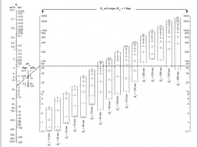
Fig. 11 Determining the position of the valve scale at a known pressure and a certain water supply
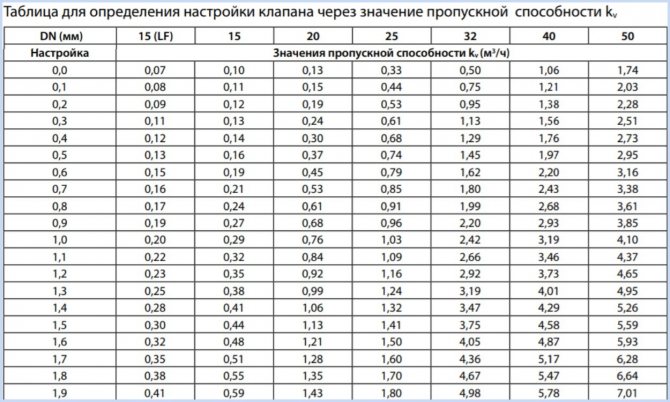
Fig.12 Example of a table for manual adjustment
Varieties of valves
Manually adjustable valve for systems with few radiators
Devices can be classified according to the way they are controlled. There are manual and automatic balancing valves.
The positive qualities of the manual look include:
- High quality work at stable pressure.
- Ease of customization.
- Possibility of installation in houses and apartments with a small number of heating batteries.
- The ability to carry out repair work without shutting down the entire system. It is enough just to close the valve in the area where the repair work will be carried out.
The optimal conditions for using a manual valve are when the number of radiators in the heating circuit in the room does not exceed 5 units. In this case, the mechanism will work with the greatest efficiency.
With a large number of radiators, manually adjusting all devices will not work. If the thermostat in the first radiator overlaps, the flow rate of the coolant increases in the subsequent ones. This leads to uneven heating of each product. The way out of the situation is to install automatic valves. Such mechanisms are placed on heating branches, which are equipped with a large number of radiators.
Automatic valve with capillary tube
The principle of operation is slightly different from that of a mechanical valve. The valve is installed in the position of maximum water flow. In the case of a decrease in the consumption of energy by the thermostat, the pressure on one of the batteries increases. At this moment, the capillary tube begins to operate, which turns on the automatic balancing valve for heating. He, in turn, analyzes the pressure drop and promptly corrects the fluid flow. The process takes place so quickly that other thermostats do not have time to overlap. As a result, the user gets a constantly balanced system.
The advantages of automatic valves include:
- The presence of a capillary tube, due to which the adjusting mechanism is triggered instantly.
- Stability of pressure readings. It is not even affected by fluctuations caused by the operation of thermostats.
There are no strict criteria for choosing a device. The equipment does not differ in the complexity of production, so even inexpensive valves will perform their task with high quality.
Characteristics
In addition to the function of regulating the flow rate of the heating agent, the balancing valve can be equipped with additional devices and settings. For example, with the ability to regulate a stepless or stepped flow rate setting, a drainage device, with a presetting lock, a filter for use in old systems, a bypass valve, a temperature cutout.
Types of balancing cranes.
All types of balancing valves have the following characteristics:
- valve operation temperature can vary from -20 to +120 degrees;
- you can directly read information without using other devices;
- the minimum length required for installation.
Auto
Such devices quickly and flexibly change the operating parameters of the system depending on the pressure drops and the flow rate of the coolant. Automatic valves are installed in pipelines in pairs.
Variety of automatic valves
When installed in the supply pipeline, a shut-off valve or balancer limits the flow of the working medium to a set value. A valve is installed in the return line, which is responsible for the uniform distribution of pressure during sudden changes.
The use of such valves makes it possible to divide the system into several independent sections, without simultaneously putting them into operation. The balance of pressure and supply of the working fluid is carried out automatically according to the specified parameters without human intervention.