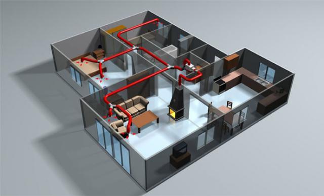
FROMThere is an opinion that gravitational heating is an anachronism in our computer age. But what if you built a house in an area where there is no electricity yet or the power supply is very intermittent? In this case, you will have to remember the old-fashioned way of organizing heating. Here's how to organize gravitational heating, and we'll talk in this article.
Gravity heating system
The gravitational heating system was invented in 1777 by the French physicist Bonneman and was designed to heat an incubator.
But only since 1818, the gravitational heating system has become ubiquitous in Europe, although so far only for greenhouses and greenhouses. In 1841, the Englishman Hood developed a method for thermal and hydraulic calculation of natural circulation systems. He was able to theoretically prove the proportionality of the circulation rates of the coolant to the square roots of the difference in the heights of the heating center and the cooling center, that is, the height difference between the boiler and the radiator. The natural circulation of the coolant in heating systems has been well studied and had a powerful theoretical foundation.
But with the advent of pumped heating systems, scientists' interest in the gravitational heating system has steadily faded away. Currently, gravitational heating is superficially illuminated in institute courses, which led to the illiteracy of specialists who install this heating system. It's a shame to say, but installers building gravitational heating mainly use the advice of "experienced" and those meager requirements that are set out in the regulatory documents. It is worth remembering that regulatory documents only dictate requirements and do not provide an explanation of the reasons for the appearance of a particular phenomenon. In this regard, among specialists there is a sufficient number of misconceptions, which I would like to dispel a little.
Detailed system description
Open gravity heating
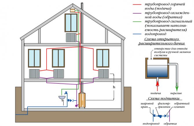
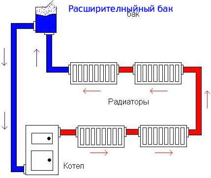
In the process of heating water, some of it will inevitably evaporate in the form of steam. For timely removal, an expansion tank is installed at the very top of the system. It performs 2 functions - excess steam is removed through the upper hole and the loss of liquid volume is automatically compensated. This scheme is called open.
However, it has one significant drawback - the relatively rapid evaporation of water. Therefore, for large branched systems, they prefer to make a closed-type gravitational heating system with their own hands. The main differences between its scheme are as follows.
- Instead of an open expansion tank, an automatic air vent is installed at the highest point of the pipeline. A closed-type gravitational heating system, in the process of heating the coolant, produces a large amount of oxygen from water, which, in addition to excess pressure, is a source of rusting of metal elements. For the timely removal of steam with a high oxygen content, an automatic air vent is installed;
- To compensate for the pressure of the already cooled coolant, a membrane expansion tank of a closed type is mounted in front of the inlet header of the boiler. If the gravitational pressure in the heating system exceeds the permissible norm, then the elastic membrane compensates for this by increasing the total volume.
Otherwise, when designing and installing a gravitational heating system only with your own hands, you can adhere to the usual rules and recommendations.
Classic two-pipe gravity heating
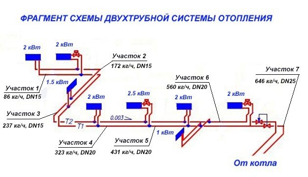
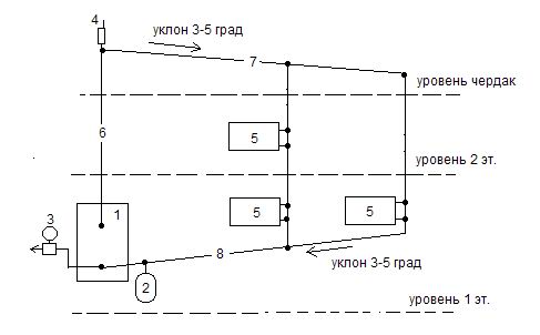
In order to understand the principle of operation of a gravitational heating system, consider an example of a classical two-pipe gravitational system, with the following initial data:
- the initial volume of the coolant in the system is 100 liters;
- height from the center of the boiler to the surface of the heated coolant in the tank H = 7 m;
- distance from the surface of the heated coolant in the tank to the center of the radiator of the second tier h1 = 3 m,
- distance to the center of the radiator of the first tier h2 = 6 m.
- The temperature at the outlet from the boiler is 90 ° C, at the inlet to the boiler - 70 ° C.
The effective circulating pressure for the second-tier radiator can be determined by the formula:
Δp2 = (ρ2 - ρ1) g (H - h1) = (977 - 965) 9.8 (7 - 3) = 470.4 Pa.
For the radiator of the first tier, it will be:
Δp1 = (ρ2 - ρ1) g (H - h1) = (977 - 965) 9.8 (7 - 6) = 117.6 Pa.
To make the calculation more accurate, it is necessary to take into account the cooling of water in the pipelines.
The essence of the system
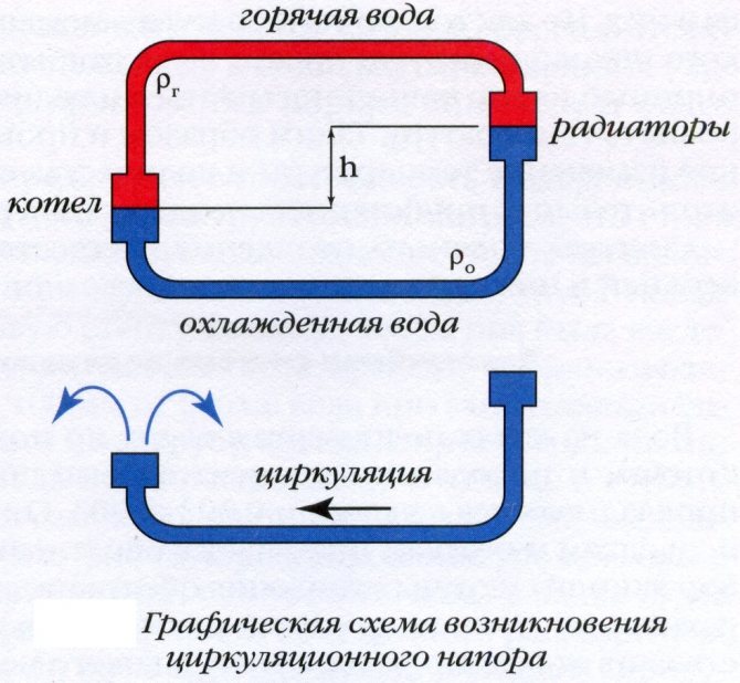
How does circulating pressure arise?
The flow movement through the pipes of a heat-carrying fluid is due to the fact that with a decrease and increase in its temperature, it changes its density and mass.
The change in the temperature of the coolant occurs due to the heating of the boiler.
In the heating pipes there is a colder liquid that has given up its heat to the radiators, therefore its density and mass is greater. Under the influence of gravitational forces in the radiator, the cold coolant is replaced by hot.
In other words, having reached the top point, hot water (it can be antifreeze) begins to be evenly distributed over the radiators, displacing cold water from them. The cooled liquid begins to descend into the lower part of the battery, after which it completely goes through the pipes into the boiler (it is displaced by the hot water coming from the boiler).
As soon as the hot coolant enters the radiator, the process of heat transfer begins. The walls of the radiator gradually heat up and then transfer heat to the room itself.
The coolant will circulate in the system as long as the boiler is running.
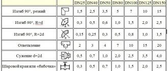
Piping for gravity heating
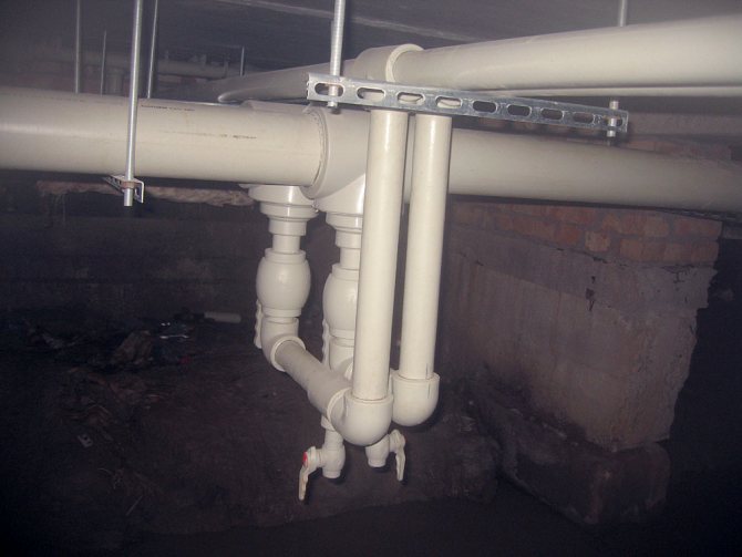
Many experts believe that the pipeline should be laid with a slope in the direction of movement of the coolant. I do not argue that ideally it should be so, but in practice this requirement is not always met. Somewhere the beam gets in the way, somewhere the ceilings are made at different levels. What will happen if you install the supply pipeline with a reverse slope?
I am sure that nothing terrible will happen. The circulating pressure of the coolant, if it decreases, then by quite a small amount (a few pascals). This will happen due to the parasitic influence that cools down in the upper filling of the coolant. With this design, the air from the system will have to be removed using a flow-through air collector and an air vent. Such a device is shown in the figure. Here, the drain valve is designed to release air at the time the system is filled with coolant. In operating mode, this valve must be closed. Such a system will remain fully functional.
Gravity decoupling schemes
There is a direct relationship between the circulating pressure within the system and the vertical distance from the point of maximum heat (top) to the point of minimum heat (bottom). In this case, the upper distribution in the gravity system will be the best option.
Three independent systems
But that's not all:
- It is recommended that the expansion vessel be fixed to the vertical main hot water supply pipe. It is mainly used for air removal.
- The supply line should be with a slope towards the direction of the coolant movement.
- In heating radiators, the movement of hot water must be organized from top to bottom (and preferably diagonally).This is a very important point.
If you use all this to build heating in your own home, then you get a schematic diagram. What about the bottom wiring? There are no objections to this option. But here you will have to face many questions. For example, how can accumulating air masses be discharged? How to increase the pressure of the coolant? Although there are options for solving these problems, they entail high costs. And why are they needed if there are schemes that are much simpler.
The movement of the cooled heat carrier
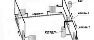
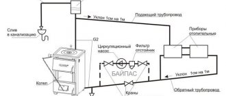
One of the misconceptions is that in a system with natural circulation, the cooled coolant cannot move upward. I also disagree with these. For a circulating system, the concept of up and down is very conditional. In practice, if the return pipeline rises in some section, then somewhere it falls to the same height. In this case, the gravitational forces are balanced. The only difficulty is in overcoming local resistance at bends and linear sections of the pipeline. All this, as well as the possible cooling of the coolant in the sections of the rise, should be taken into account in the calculations. If the system is correctly calculated, then the diagram shown in the figure below has the right to exist. By the way, at the beginning of the last century, such schemes were widely used, despite their weak hydraulic stability.
A simplified version of the heating system with natural circulation of the heat carrier
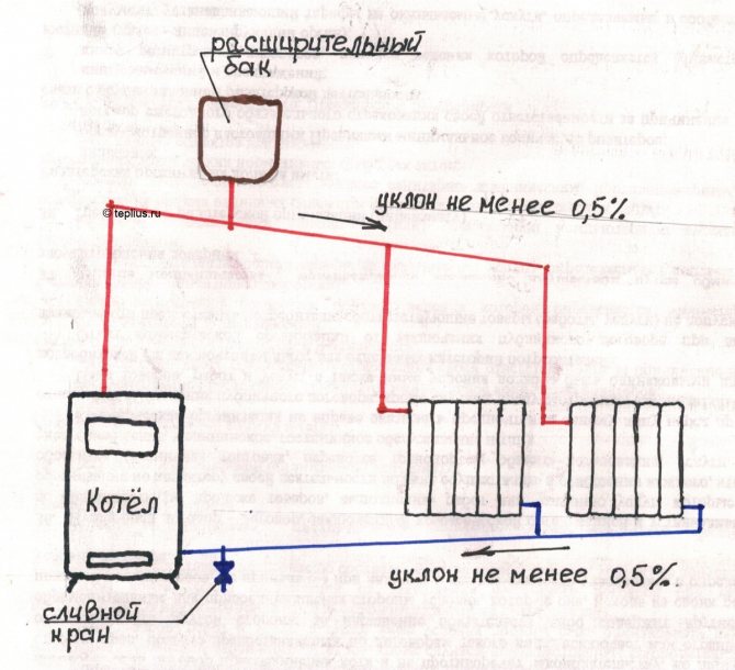
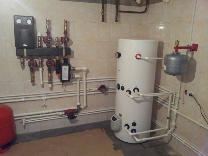
The boiler is placed, the place for it is determined in advance. A supply riser is brought out from the boiler, and in a predetermined place upwards, as far as possible in the building. As a rule, in the attic or in some storage room of the upper floor of a country house.
An expansion tank with an overflow pipe led to the utility room, where there is a sewage system, is installed to the riser at the top. If the expansion tank is supposed to be closed, then it is installed on the return line in the boiler room or another room, an auto-air vent is installed at the highest point. A security group is also installed in the boiler room on the 1st floor. The boiler must be installed as low as possible, in a pit or basement. It is prohibited to install a gas boiler in the basement. From the top point, where an open expansion tank or auto-air vent was installed, a lowering is made. It turns out a pressure loop. Next, let's talk about what a pressure loop is for.
Location of radiators
They say that with the natural circulation of the coolant, the radiators, without fail, must be located above the boiler. This statement is true only when the heating devices are located in one tier. If the number of tiers is two or more, the radiators of the lower tier can be located below the boiler, which must be checked by hydraulic calculation.
In particular, for the example shown in the figure below, with H = 7 m, h1 = 3 m, h2 = 8 m, the effective circulating pressure will be:
g · = 9.9 · [7 · (977 - 965) - 3 · (973 - 965) - 6 · (977 - 973)] = 352.8 Pa.
Here:
ρ1 = 965 kg / m3 is the density of water at 90 ° C;
ρ2 = 977 kg / m3 is the density of water at 70 ° C;
ρ3 = 973 kg / m3 is the density of water at 80 ° C.
The resulting circulating pressure is sufficient for the reduced system to work.
Radiator layout
One floor
As already mentioned, the author is a practitioner and will dare to give recommendations for the design of the wiring, based on his own experience.
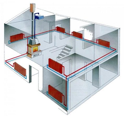
For a one-story house, the best scheme is the so-called Leningrad, or barrack heating scheme.
What does it represent in the correct implementation?
- The main contour encircles the entire house around the perimeter. The only permissible circuit break is the same valve on the bypass at the place where the pump is installed. Material - pipe not thinner than DN 32.
Useful: for some reason, natural circulation is associated with many exclusively with steel pipes.In vain: in this case, you can safely use even polypropylene without reinforcement. An open system means no overpressure; the temperature during normal circulation will never exceed the boiling point of water.
- The heaters cut parallel to the contour. Connection - bottom or diagonal.
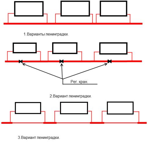
The first sidebar option is correct. The second and third for our purposes are categorically not suitable.
- On the connections to the radiator (they are usually made with a DU20 pipe), valves or a valve-choke pair are placed. Shut-off valves will allow you to turn off the radiator completely for repair; in addition, it makes balancing the heating devices possible.
- At the bottom connection, an air vent is installed in the upper radiator plugs - a Mayevsky tap, a valve or an ordinary water tap.
Two floors
How to implement natural circulation heating in a two-story house?
Let's start with what not to do.
It is impossible to organize several circuits connected to the boiler in parallel and different in length. What the instruction is connected with is easy to understand: a shorter circuit will bypass a long one, passing most of the coolant through itself.
You cannot use the classic two-pipe system without balancing valves or throttles. In this case, water will flow only through nearby heating devices. The author had a chance to face the consequences of such a heating implementation: during the first serious frosts, the distant radiators were defrosted.
Such a wiring will become operational only after balancing the risers with chokes. Without it, all the water will circulate only through nearby heating devices.
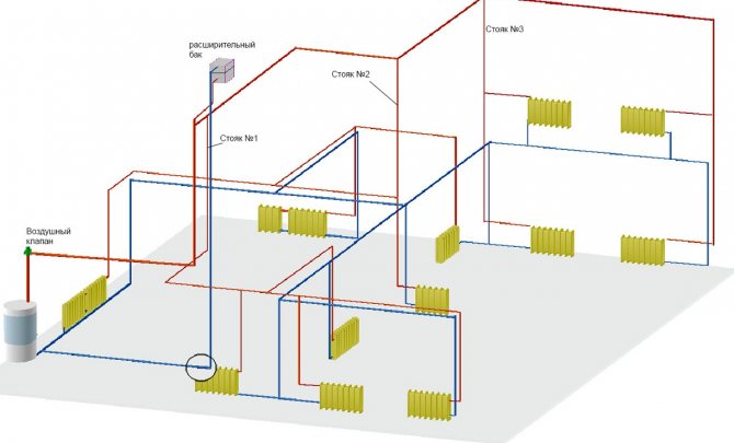
An easy-to-implement and hassle-free wiring diagram might look like this:
- The booster manifold ends on the second floor or attic with an expansion tank. Filling with a diameter of 40-50 millimeters begins directly from it with a constant slope.
- The lower contour (return) encircles the house along the perimeter at the floor level of the first floor.
Useful: yes, moving the bottom filling into the basement, if available, will be better both in terms of aesthetics and in terms of the efficiency of the scheme. But this should only be done if the temperature in the basement does not drop below zero, even with a cold boiler. However, if your circuit is with antifreeze or other antifreeze, you can not be afraid of defrosting.
- Radiators open the risers; in this case, a throttle is installed on at least one heater in the riser. Balancing, remember? Without it, we again get extremely uneven heating of the batteries.
The diagram uses a different, less accurate way of balancing the risers. There are more heating devices on the one closest to the boiler. This scheme is also workable.
If it is possible to take the spills to the attic and to the basement, this has at least one good side. Thus, one of the problems of the gravitational system will be solved - the aesthetic one. Yet a thick, sloped pipe rarely adorns a home.
The flip side of the coin is that with the highest quality thermal insulation, a large amount of heat from a thick filling will be dissipated aimlessly, outside the living quarters.
With a large diameter, the filling dissipates a lot of heat. In the basement, it will disappear aimlessly.
Gravity heating - replacing water with antifreeze
I read somewhere that gravitational heating, designed for water, can be painlessly switched to antifreeze. I want to warn you against such actions, since without proper calculation, such a replacement can lead to a complete failure of the heating system. The fact is that glycol-based solutions have a significantly higher viscosity than water. In addition, the specific heat capacity of these liquids is lower than that of water, which will require, other things being equal, an increase in the circulation rate of the coolant.These circumstances significantly increase the design hydraulic resistance of the system filled with coolants with a low freezing point.
Gravity heating system made of polypropylene: advantages over metal
A gravity heating system can be made not only from metal pipes, but also from more modern material. Polypropylene has deservedly become such a material. A heating system made of polypropylene pipes can be hidden under trim or cladding. As a result of these actions, the area of the room will not decrease, but the neatness and aesthetics of the appearance of the polypropylene system will pleasantly please you.
Today, a polypropylene heating system is a worthy competitor to cast iron and metal ones.
Using modern material, it is quite possible to make a heating system on your own. In this case, polypropylene is the best suited for this task. Pipes made from polypropylene have a number of advantages.
Advantages of polypropylene pipes:
- Polypropylene pipes are not subject to corrosion;
- They have a low coefficient of thermal conductivity;
- No deposits are formed on the inner surfaces of the pipes;
- The price of polypropylene is lower than cast iron and metal;
- Neutrality to aggressive environments;
- Plastic;
- Resistant to temperature changes;
- Ease of installation;
- Long service life.
This material differs significantly from metal and cast iron both in technical characteristics and in the way of working with it. Naturally, the tool required to carry out these works will require a different one. The process of soldering polypropylene pipes is not complicated and very fast, but it requires certain skills and knowledge of technology.
Using an open expansion tank
Practice shows that it is necessary to constantly top up the coolant in an open expansion tank, as it evaporates. I agree that this is really a big inconvenience, but it can be easily eliminated. To do this, you can use an air tube and a hydraulic seal, installed closer to the lowest point of the system, next to the boiler. This tube serves as an air damper between the hydraulic seal and the coolant level in the tank. Therefore, the larger its diameter, the lower the level of level fluctuations in the water seal tank will be. Particularly advanced craftsmen manage to pump nitrogen or inert gases into the air tube, thereby protecting the system from air penetration.
cons and pros
What does gravity heating look like against the background of a forced circulation system? Should you opt for it when designing your own cottage?
Benefits
- The system is completely fault-tolerant. There are no moving or wearing parts in it; it does not depend on external factors, including unstable power supply outside the city.
- The gravity circuit is self-adjusting. The colder the return flow in it, the faster the circulation of the coolant: since it has a higher density when compared with the scales heated in the boiler.
- Finally, when designing this system, you do not need to deal with complex calculations, you do not need special skills: such schemes were designed by our grandfathers. In rural areas, to this day, it is possible to find circuits attached to a metal tube heat exchanger placed in a Russian stove.
Shortcomings
Not without them.
- The system warms up rather slowly. It can take one and a half to two hours from the boiler firing up to the batteries reaching the operating temperature.
But: thanks to the huge volume of the coolant, they will also cool down slowly. Especially if cast iron heating radiators or massive metal registers are installed as heating devices.
- The simplicity of the system does not indicate that its price will be significantly lower when compared with the alternatives.A solid filling diameter will entail high costs. Here is an excerpt from the current price page for a reinforced polypropylene pipe from one of the Russian companies:
| Diameter, mm | Price per running meter, rubles |
| 20 | 52,28 |
| 25 | 67,61 |
| 32 | 111,76 |
| 40 | 162,16 |
| 50 | 271,55 |
- Without balancing, the temperature spread between the heatsinks can be noticeable.
- Finally, with insignificant heat transfer from the boiler, the bottling areas taken out to the attic or to the basement in severe frosts can be fully captured by ice.
Using a circulation pump in gravity heating
In a conversation with one installer, I heard that a pump installed on the bypass of the main riser cannot create a circulation effect, since the installation of shut-off valves on the main riser between the boiler and the expansion tank is prohibited. Therefore, you can put the pump on the bypass of the return line, and install a ball valve between the pump inlets. This solution is not very convenient, since every time before turning on the pump, you must remember to turn off the tap, and after turning off the pump, open it. In this case, the installation of a check valve is impossible due to its significant hydraulic resistance. To get out of this situation, the craftsmen are trying to remake the check valve into a normally open one. Such "modernized" valves will create sound effects in the system due to constant "squelching" with a period proportional to the speed of the coolant. I can suggest another solution. A float check valve for gravity systems is installed on the main riser between the bypass inlets. The valve float in natural circulation is open and does not interfere with the movement of the coolant. When the pump is turned on in the bypass, the valve shuts off the main riser, directing all flow through the bypass with the pump.
In this article, I have considered far from all the misconceptions that exist among specialists installing gravitational heating. If you liked the article, I am ready to continue it with answers to your questions.
In the next article I will talk about building materials.
RECOMMEND TO READ MORE:
Advantages and disadvantages
Suppose we are designing a heating system in a private house from scratch. Is it worth relying on natural circulation or is it better to take care of buying a circulation pump?
pros
- Before us is a self-regulating system. The circulation rate will be the greater, the colder the coolant in the return pipe. This feature of the system follows from the very used physical principle.
- Fault tolerance is beyond praise. In fact, what can happen to the thick pipe circuit and radiators? There are no moving and wearing parts; As a result, gravitational heating systems can operate without repair and maintenance for up to half a century. Think about it: you can do something yourself that will serve your children and grandchildren!
- Energy independence is also a huge plus. Imagine a prolonged power outage in the middle of winter. What will you do without a pump if a blizzard hits the power line poles or an accident occurs at the regional substation?

Broken power lines can recover for several days. It is not fun to remain without heating for this time.
- Finally, such a system is easy to manufacture. You don't have to puzzle over its device: it is simple and straightforward.
Minuses
Do not flatter yourself: everything is not as rosy as it might seem at first glance.
- The system will have a high thermal inertia. Simply put, from the moment when you light up the boiler, it can take more than one hour to warm up the latter in the radiator circuit.
- The simplicity of the boiler wiring and piping does not mean its cheapness. You will have to use a thick pipe, the price of a running meter of which is quite high. However, it will additionally increase the area of heat exchange between heating and air.
- With some wiring diagrams, the temperature spread between the heatsinks will be significant.
- Due to the low circulation rate at a low heating intensity, there are very real chances to freeze the expansion tank and the part of the circuit taken out to the attic.
A little bit of common sense
Dear reader, let's stop for a second and think: why, in fact, in our minds natural and forced circulation is something mutually exclusive?
The most reasonable solution would be the following:
- We are designing a system capable of operating as a gravitational one.
- We break the circuit in front of the boiler with a valve. Of course, without reducing the pipe section.
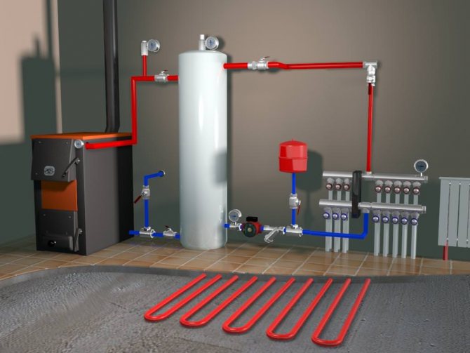
- We cut in the bypass of the valve with a smaller pipe diameter and install a circulation pump on the bypass. If necessary, it is cut off by a pair of valves; a sump is mounted in front of the pump along the water flow.
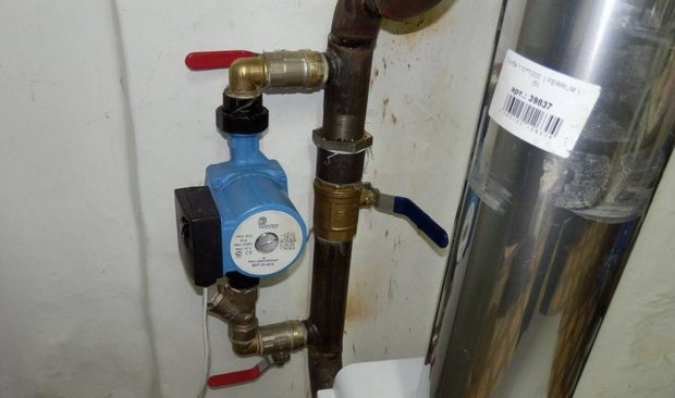
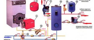
The photo shows the correct pump inset. The system can work with both forced and natural circulation.
What are we buying?
A complete heating system with forced circulation and all its benefits:
- Uniform heating of all heating devices;
- Rapid heating of rooms after starting the boiler.
It is not at all necessary to make the system closed: the pump can work perfectly without excess pressure. If the electricity goes out - no problem: we just cut off the pump and open the bypass valve. The system continues to function as a gravitational one.
Determination of the coolant flow rate and pipe diameters
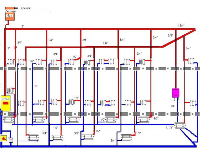
First, each heating branch must be divided into sections, starting from the very end. The breakdown is done by water consumption, and it varies from radiator to radiator. This means that after each battery a new section begins, this is shown in the example that is presented above. We start from the 1st section and find the mass flow rate of the coolant in it, focusing on the power of the last heater:
G = 860q / ∆t, where:
- G is the flow rate of the coolant, kg / h;
- q is the heat output of the radiator at the site, kW;
- Δt is the temperature difference in the supply and return pipelines, usually take 20 ºС.
For the first section, the calculation of the coolant looks like this:
860 x 2/20 = 86 kg / h.
The result obtained must be immediately applied to the diagram, but for further calculations we will need it in other units - liters per second. To make a translation, you need to use the formula:
GV = G / 3600ρ, where:
- GV - volumetric water flow rate, l / s;
- ρ is the density of water, at a temperature of 60 ºС is 0.983 kg / liter.
We have: 86/3600 x 0.983 = 0.024 l / s. The need to translate units is explained by the need to use special ready-made tables to determine the diameter of a pipe in a private house. They are freely available and are called Shevelev Tables for Hydraulic Calculations. You can download them by following the link: https://dwg.ru/dnl/11875
In these tables, the values of the diameters of steel and plastic pipes are published, depending on the flow rate and speed of movement of the coolant. If you open page 31, then in table 1 for steel pipes in the first column the flow rates are indicated in l / s. In order not to make a complete calculation of pipes for the heating system of a private house, you just need to choose the diameter according to the flow rate, as shown in the figure below:
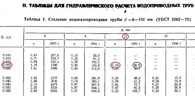
Note. In the left column below the diameter, the speed of the movement of the water is immediately indicated. For heating systems, its value should be within 0.2-0.5 m / s.
So, for our example, the inside dimension of the passage should be 10 mm. But since such pipes are not used in heating, we safely accept the DN15 pipeline (15 mm). We put it down on the diagram and go to the second section. Since the next radiator has the same power, there is no need to apply the formulas, we take the previous water flow and multiply it by 2 and get 0.048 l / s. We turn to the table again and find the nearest suitable value in it. At the same time, do not forget to monitor the water flow speed v (m / s) so that it does not exceed the indicated limits (in the figures it is marked in the left column with a red circle):
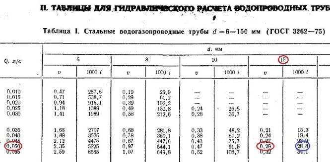
Important.For heating systems with natural circulation, the speed of movement of the coolant should be 0.1-0.2 m / s.
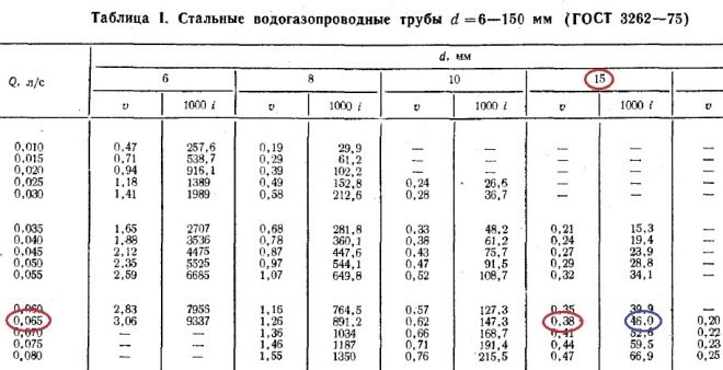
As you can see in the figure, section No. 2 is also laid with a DN15 pipe. Further, according to the first formula, we find the flow rate at section No. 3:
860 x 1.5 / 20 = 65 kg / h and translate it into other units:
65/3600 x 0.983 = 0.018 l / s.
Adding it to the sum of the costs of the two previous sections, we get: 0.048 + 0.018 = 0.066 l / s and again refer to the table. Since in our example, not the calculation of the gravitational system is done, but the pressure one, the DN15 pipe is suitable for the speed of the coolant this time too:
Going this way, we calculate all the areas and put all the data on our axonometric diagram: