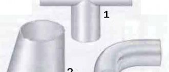
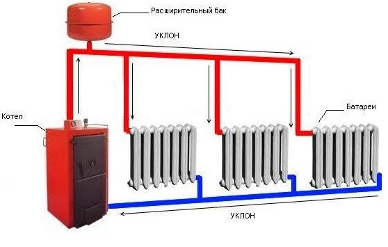
What is forced circulation for?
The natural circulation of the coolant occurs according to physical laws: heated water or antifreeze rises to the top point of the system and, gradually cooling down, goes down, returning to the boiler. For successful circulation, it is necessary to strictly maintain the angle of inclination of the straight and return pipes. With a small length of the system in a one-story house, this is easy to do, and the height difference will be small.
For large houses and multi-storey buildings. Such a system is most often unsuitable - it may form air jams, disturb circulation and, as a result, overheat of the coolant in the boiler. This situation is dangerous and can cause damage to system components.
Therefore, a circulation pump is installed in the return pipe, immediately before entering the boiler heat exchanger, which creates the required pressure and water circulation rate in the system. At the same time, the heated coolant is promptly discharged into the heating devices, the boiler operates normally, and the microclimate in the house remains stable.
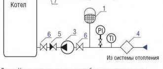
Diagram: elements of the heating system
- the system works stably in buildings of any length and number of storeys;
- you can use pipes of a smaller diameter than with natural circulation, which saves the cost of purchasing them;
- it is allowed to place pipes without a slope and lay them hidden in the floor;
- warm water floors can be connected to the forced heating system;
- stable temperature regime prolongs the life of fittings, pipes and radiators;
- it is possible to regulate the heating for each room.
Disadvantages of a forced circulation system:
- calculation and installation of the pump is required, connecting it to the mains, which makes the system volatile;
- the pump makes a noise during operation.
The disadvantages are successfully solved by the correct placement of the equipment: the pump is placed in a separate room of the boiler room next to the heating boiler and a backup power source is installed - a battery or a generator.
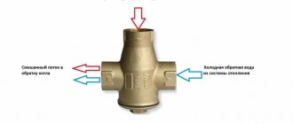
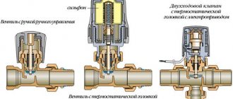
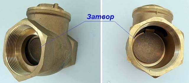
Bivalve
For heating systems with large pipe sections, a special type of valves has been developed - two-leaf. It is equally effective for both the supply pipe and the return - the principle of operation will be the same.
Subject to the observance of the operating conditions, the flaps of the check valve on the heating return line and on the supply line open freely by the pressure of the coolant. When the working pressure changes and the water flow is incorrect, a special axis with flaps attached to it closes the inner lumen of the pipe.
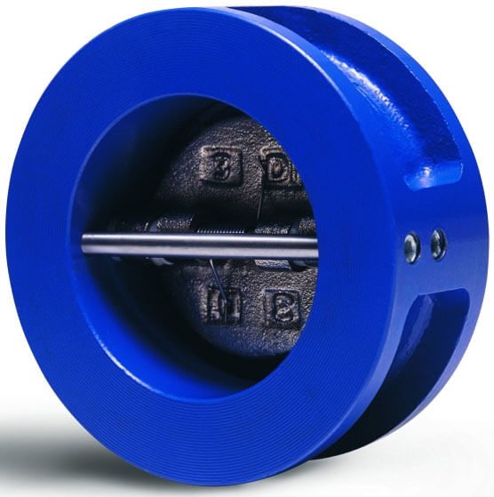
It should be noted that this shut-off valve is the most reliable, due to which it is in demand in high-pressure systems.
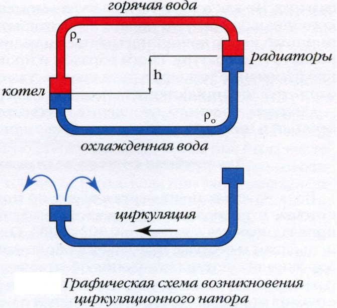
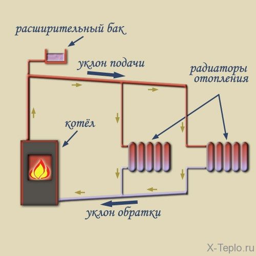
The principle of operation of a gravity heating system
The principle of operation of heating looks simple: water moves through the pipeline, driven by the hydrostatic head, which appeared due to the different mass of heated and cooled water. Such a structure is also called gravity or gravity. Circulation is the movement of the cooled liquid in the batteries and the heavy liquid under the pressure of its own mass down to the heating element, and the displacement of the light heated water into the supply pipe. The system works when the natural circulation boiler is located below the radiators.
In open circuits, it communicates directly with the external environment, and excess air escapes into the atmosphere. The volume of water that increased from heating is eliminated, the constant pressure is normalized.
Natural circulation is also possible in a closed heating system if it is equipped with an expansion vessel with a membrane. Sometimes open-type structures are converted into closed ones. Closed circuits are more stable in operation, the coolant does not evaporate in them, but they are also independent of electricity. What affects the circulating head
The water circulation in the boiler depends on the difference in density between the hot and cold liquid and on the height difference between the boiler and the lowest radiator. These parameters are calculated even before the installation of the heating circuit is started. Natural circulation occurs because the return temperature in the heating system is low. The coolant has time to cool down, moving through the radiators, it becomes heavier and, with its mass, pushes the heated liquid out of the boiler, forcing it to move through the pipes.
Boiler water circulation diagram
The height of the battery level above the boiler increases the pressure, helping the water to more easily overcome the resistance of the pipes. The higher the radiators are in relation to the boiler, the greater the height of the cooled return column and with the greater the pressure it pushes the heated water upward when it reaches the boiler.
Density also regulates the pressure: the more the water heats up, the less its density becomes in comparison with the return. As a result, it is pushed out with more force and the pressure increases. For this reason, gravity heating structures are considered self-regulating, because if you change the temperature of heating the water, the pressure on the coolant will also change, which means that its consumption will change.
During installation, the boiler should be placed at the very bottom, below all other elements, in order to ensure a sufficient head of the coolant.
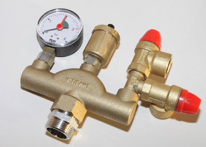
What is a safety valve for?
Some of this has already been mentioned in the introductory part of the article. Everything is simple - with an increase in the temperature in the heating system (during the operation of the boiler), the coolant tends to expand.
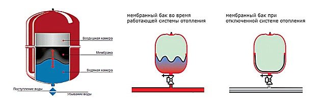
In part, he succeeds - just for such purposes, an expansion tank is provided in any system. And in our time, systems began to be made predominantly of a closed type, that is, with a sealed expansion tank of a membrane or balloon type.
In such tanks there is an air chamber, which is pre-inflated with a certain pressure. Under the action of the coolant expanding in the volume (and for it this is the only way to free expansion), the air chamber contracts, the pressure in it and in the system as a whole increases.
Both the device and the principle of operation of the expansion tank of a closed heating system are not particularly complicated.
Expert opinion: E.V. Afanasyev
Chief editor of the Stroyday.ru project. Engineer.
With correctly calculated parameters of the heating system, such a compensation link is quite enough to maintain the optimal balance of temperature, volume and pressure of the coolant. Moreover, in autonomous systems, they never operate with too high pressure indicators. As a rule, with forced circulation using pumping equipment, the pressure in the pipes of the circuits rarely rises above the border of two technical atmospheres (2 atm, 2 bar or 0.2 MPa), and even then only at the maximum heating medium heating temperatures. Accordingly, the air chamber of the expansion tank is pre-pumped to about 1.5 atm.
In such systems, a maximum pressure of 3 atmospheres will be more than enough, and it is not necessary to rise above it. This can adversely affect the integrity of the pipes of the laid circuits, connecting nodes, heat exchangers. Some radiators and convectors do not like high pressure.
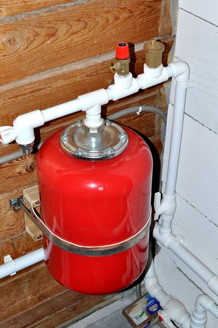
In closed heating systems, the safety valve works in “duet” with an expansion membrane tank.
If everything is calculated correctly during the design of the system, then the pressure should not rise above the threshold set for it. But anything happens, for example, a temporary failure of the thermostatic control of the boiler. Or a breakthrough of the expansion tank membrane, the release of air from its "dry" chamber due to a malfunction of the nipple. Other troubles also happen. It is in such conditions that the pressure in the system can begin to rise uncontrollably, cross the upper permissible limit. What does this sometimes lead to - it is better not to tell ...
And in order to avoid the consequences, a safety valve is just needed. As soon as the pressure reaches the limit mark, it is triggered, the valve opens and releases the excess coolant into the drain. Thus, normalizing the pressure level, giving the owners time to put the system in order, to find the malfunction that caused the emergency.
That is, the valve is selected (or adjusted, if such an option is provided) for the maximum allowable pressure of the coolant in the heating circuit.
The close relationship between the general parameters of the heating system, the expansion tank installed in it and the safety valve can be well tracked on the online calculator below.
Calculator for calculating the minimum required volume of an expansion tank for a closed heating system
Go to calculations
As you can see, the calculation can be carried out for both water and non-freezing coolant. the calculator program takes into account the difference in volumetric expansion of these liquids at an average heating temperature of up to 75 ÷ 80 ℃.
One more nuance. For the calculation, you must indicate the total volume of the heating system. You can, of course, "dance" from the power, but this gives a considerable error. Lovers of accuracy can be advised another algorithm for determining this parameter of the system.
How to calculate the total volume of the heating medium in the heating system?
The answer suggests itself - to sum up the volumes of all pipes and all devices connected to the circuit, from the cat to the last battery. Difficult and cumbersome? - nothing to worry about if you use the proposed on our portal calculator for calculating the total volume of the heating system.
Pipes for natural circulation systems
When choosing the diameter of the pipes, not only the size of the system and the number of radiators play a role, but also the material from which they are made, or rather, the smoothness of the walls. For gravitational systems, this is a very important parameter. The worst situation is with ordinary metal pipes: the inner surface is rough, and after use it becomes even more uneven due to corrosion processes and accumulated deposits on the walls. Therefore, such pipes take the largest diameter.
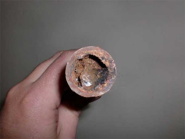
Steel pipes after a few years may look like this
From this point of view, metal-plastic and reinforced polypropylene are preferable. But in metal-plastic fittings are used that significantly narrow the lumen, which can become critical for gravity systems. Therefore, reinforced polypropylene looks more preferable. But they have restrictions on the temperature of the coolant: the operating temperature is 70 ° C, the peak is 95 ° C. For products made of special PPS plastic, the operating temperature is 95 ° C, the peak is up to 110 ° C. So, depending on the boiler and the system as a whole, you can use these pipes, on the condition that they are quality branded products, and not a fake. Read more about polypropylene pipes here.
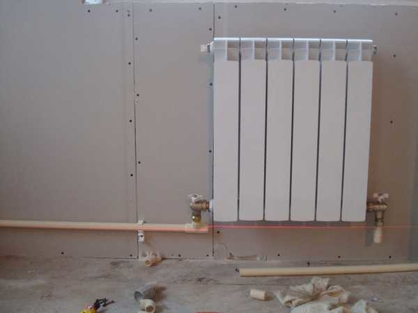
Metaloplastic and polypropylene can also be used for the installation of heating systems
But if you plan to install a solid fuel boiler. then no polypropylene can withstand such heat loads.In this case, either still use steel, or galvanized and stainless steel on threaded joints (do not use welding when installing stainless steel, since the seams leak very quickly)
Copper is also suitable (it is written about copper pipes here), but it also has its own characteristics and must be handled carefully: it will not behave normally with all coolants, and it is better not to use it in one system with aluminum radiators (they quickly collapse )
A feature of systems with natural circulation is that they cannot be calculated due to the formation of turbulent flows that cannot be calculated. They are designed based on experience and averaged, empirically derived norms and rules. Basically, the rules apply:
- raise the acceleration point as high as possible;
- do not narrow the supply pipes;
- supply a sufficient number of radiator sections.
Then one more is used: from the place of the first branch and each subsequent one is led with a pipe of a diameter smaller by a step. For example, a 2-inch pipe goes from the boiler, then from the first branch 1 ¾, then 1 ½, etc. The scrap is collected from a smaller diameter to a larger one.
There are several more features of the installation of gravitational systems. First, it is advisable to make pipes with a slope of 1-5%, depending on the length of the pipeline. In principle, with a sufficient temperature and altitude difference, horizontal wiring can also be made, the main thing is that there are no areas with a negative slope (inclined in the opposite direction), which, due to the formation of air jams in them, will block the movement of the water flow.
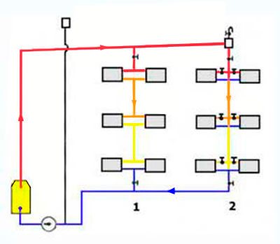
One-pipe gravity system with vertical distribution on two wings (contours)
The second feature is that an expansion tank and / or an air vent must be installed at the highest point of the system. The expansion tank can be open (the system will also be open) or membrane (closed). When installed open, there is no need to exhaust air; it collects at the highest point - in the tank and goes out into the atmosphere. When installing a membrane-type tank, an automatic air vent is also required. With horizontal wiring, the "Mayevsky" taps on each of the radiators will not interfere - with their help it is easier to remove all air jams in the branch.
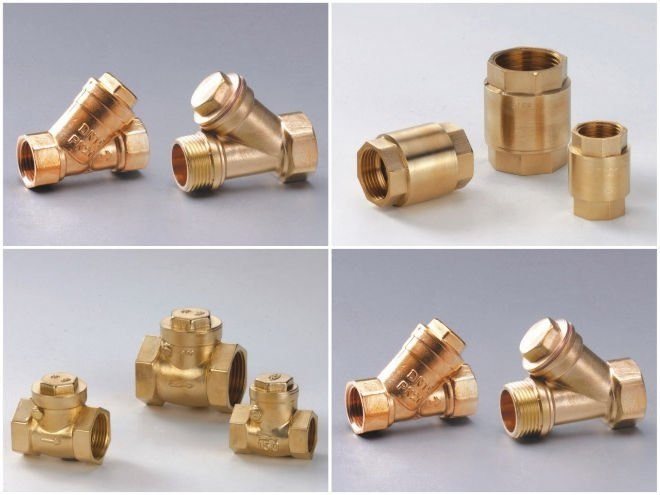
Varieties of devices
There are several types of shut-off valves, and often different types of products are installed on the supply and return circuits. Depending on the metal used, the check valve may have its own characteristics.
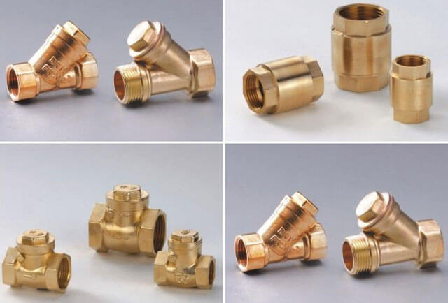
The most commonly used brass, cast iron and steel products. In addition, check valves differ in their design. Let's consider the main options.
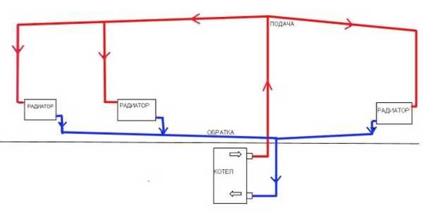
Installation diagram of gravity heating systems
Since the circulation of water in the heating system takes place without the participation of a pump, for the unimpeded flow of liquid through the highways, they must have a diameter larger than in a circuit where water circulation is forced. The gravity system functions by reducing the resistance that water has to overcome: the farther the pipe is from the boiler, the wider it is.
Water heating with natural circulation can have top or bottom wiring. When a two-pipe wiring is designed, heated water enters directly into each battery, and does not pass them alternately, as in a one-pipe scheme.
The upper wiring, in which the coolant first rises to the ceiling, and from there descends to the batteries, is best suited to carry out the installation of such a structure. If the layout is planned to be lower. then an accelerating circuit is constructed: a height difference at which the water from the boiler first goes up, where at the top of the pipeline it enters the expansion tank, and then it goes down to the heating radiators.
The higher the heater is located, the higher the pressure inside the pipeline.Therefore, the batteries on the upper floors often warm up better than those on the lower ones. Accordingly, if you make two-pipe heating with natural circulation, the batteries placed at the same level with the boiler or below do not warm up enough.
To avoid such a situation, the boiler room is thoroughly buried, providing a sufficiently high pressure for the coolant to pass through the pipes at the required speed. The boiler is placed in a basement, approximately 3 meters below the center of the lowest heating element. Pipes with hot water, on the contrary, are lifted up as much as possible, placing an expansion tank at the highest point of the structure, and then the water from the supply pipe goes down to the radiators.
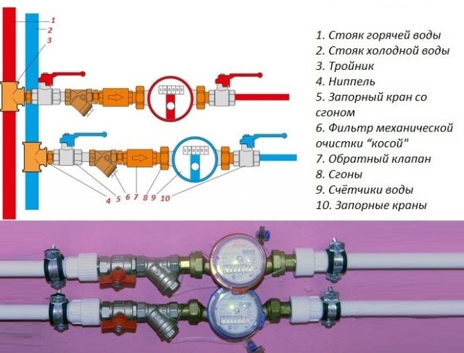
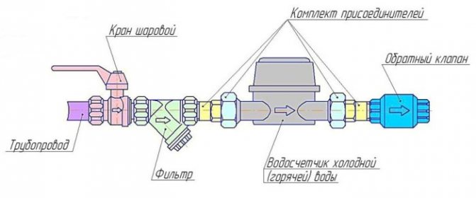
Varieties of devices and their areas of application
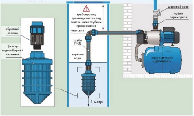
The selection of the device is dictated by the conditions in which it will be used; it depends on the type of heating networks and their internal pressure. Incorrectly selected - the mechanism can itself cause emergencies. For example, an insert part, which is offered to be placed inside a cold water meter, can completely block its current, with insufficient pressure, or significantly limit it. On the other hand, installed at the water supply inlet, it will prevent the leakage of the coolant, while maintaining the pressure, pressure and amount of water in the system.
Gravity check valve for heating
It is also called a cracker valve, it is used only in gravity systems, being installed, as a rule, at the inlet to the boiler. It consists of a metal "petal" that is tightly pressed against the edge by means of a spring.
The spring in the gravity check valve is rather weak and does not interfere with the natural circulation of the coolant.
The spring in such a device is rather weak, and does not interfere with the natural circulation of the coolant, like the next presented option.
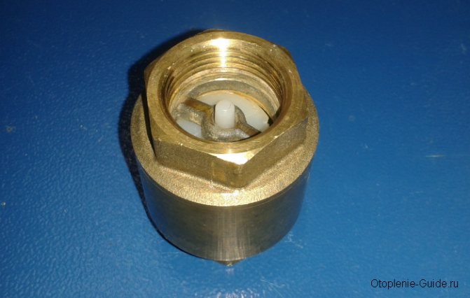
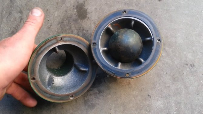
Ball valve for heating
It is used less often, since there is a danger that the ball, which moves inside the mechanism, opening and closing the flow of water, can jam in one position and then the device will not perform its work properly.
This feature was the reason that today the ball check valve is practically not used in heating networks of private houses.
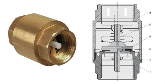
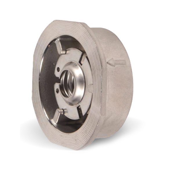
Poppet
This product is used in networks that operate with a pump and also have several active heating circuits. This is due to the fact that the spring located inside the device has a high stiffness, therefore, resistance.
Inside there is a metal or plastic disc (metal is always used for heating), combined with a bushing on which a spring is fixed. Thus, when a proper pressure occurs in the pipe, the plate rises and does not interfere with the flow of the coolant. However, as soon as the pressure drops, the opening closes, preventing the outflow of water in the opposite direction.
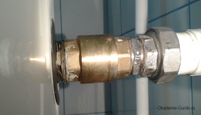
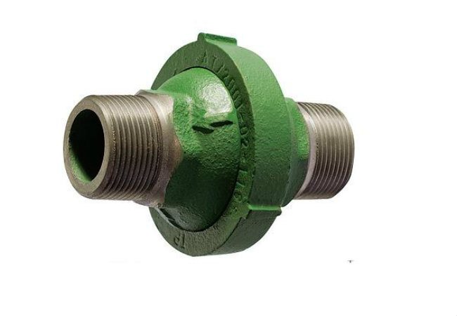
Muff
All the products discussed above were completely autonomous, and did not obey external influences, working only in one direction. But in cases where it is necessary, for example, to drain the coolant from the pipes, a device is needed that makes it possible to open the coolant current in the opposite direction - just such a device is a coupling or valve valve.
When it is necessary to drain the coolant from the pipes, a device is needed that makes it possible to open the coolant flow in the opposite direction; for this, a coupling or valve valve is used.
The choice between a coupling and a valve is most often due to the internal working pressure of the network, if it is high, a valve is used, if it is medium, the coupling will be sufficient.
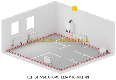
Types of one-pipe system wiring
In a one-pipe system, there is no separation between a forward and a return pipe.The radiators are connected in series, and the coolant passing through them gradually cools down and returns to the boiler. This feature makes the system economical and simple, but requires setting the temperature regime and correct calculation of the power of the radiators.
A simplified version of a one-pipe system is only suitable for a small one-story house. In this case, the pipe passes through all radiators directly, without temperature control valves. As a result, the first batteries along the course of the coolant turn out to be much hotter than the last ones.
This layout is not suitable for extended systems. after all, the cooling of the coolant will be significant. For them, a single-pipe system "Leningradka" is used, in which the common pipe has adjustable branches for each radiator. As a result, the coolant in the main pipe is more evenly distributed throughout all rooms. The layout of a single-pipe system in multi-storey buildings is divided into horizontal and vertical.
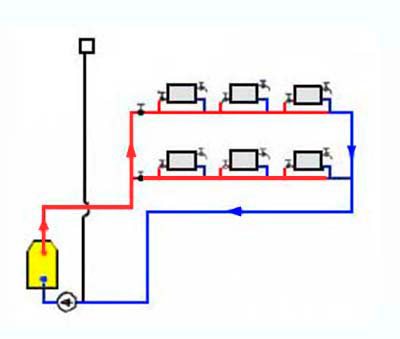
Horizontal routing
With horizontal routing, the straight pipe rises to the upper floor along the main riser. A horizontal pipe extends from it on each floor, passing sequentially along all the batteries on this floor.
They are combined into a return pipe and fed back to the boiler or boiler. Temperature control taps are located on each floor, and Mayevsky taps are on each radiator. Horizontal wiring can be performed both flow-through and according to the Leningradka system.
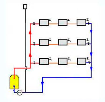
Vertical layout
With this type of wiring, the hot coolant rises to the uppermost floor or attic, and from there, along vertical risers, it passes through all floors to the lowest. There the risers are combined into a return line. A significant drawback of this system is uneven heating on different floors, which cannot be adjusted with a flow-through system.
The choice of a wiring system for a private house depends mainly on its layout. With a large area of each floor and a small number of storeys of the house, it is better to choose a vertical layout, so you can achieve a more even temperature in each room. If the area is small, it is better to choose a horizontal layout, as it is easier to regulate. In addition, with a horizontal type of routing, you do not have to make unnecessary holes in the floors.
Video: one-pipe heating system
The principle of operation of the system with natural circulation
The heating scheme of a private house with natural circulation is popular due to the following advantages:
- Simple installation and maintenance.
- No need to install additional equipment.
- Energy independence - no additional electricity costs are required during operation. In the event of a power outage, the heating system continues to work.
The principle of operation of water heating, using gravity circulation, is based on physical laws. When heated, the density and weight of the liquid decreases, and when the liquid medium cools down, the parameters return to their original state.
At the same time, there is practically no pressure in the heating system. In heat engineering formulas, a ratio of 1 atm is taken. for every 10 m of the head of the water column. The calculation of the heating system of a 2-storey building will show that the hydrostatic pressure does not exceed 1 atm. in one-story buildings 0.5-0.7 atm.
Since the liquid increases in volume during heating, an expansion tank is required for natural circulation. The water passing through the boiler water circuit heats up, which leads to an increase in volume. The expansion tank should be located on the coolant supply, at the very top of the heating system. The task of the buffer tank is to compensate for the increase in liquid volume.
A self-circulation heating system can be used in private houses, making the following connections possible:
- Connection to underfloor heating - requires the installation of a circulation pump, only on the water circuit laid in the floor. The rest of the system will continue to work with natural circulation. After a power outage, the room will continue to be heated using installed radiators.
- Working with an indirect water heating boiler - connection to a natural circulation system is possible, without the need to connect pumping equipment. For this, the boiler is installed at the top of the system, just below the closed or open air expansion tank. If this is not possible, then the pump is installed directly on the storage tank, additionally installing a check valve to avoid recirculation of the coolant.
In systems with gravitational circulation, the movement of the coolant is carried out by gravity. Due to natural expansion, the heated liquid rises up the booster section, and then, at a slope, "flows" through the pipes connected to the radiators back to the boiler.
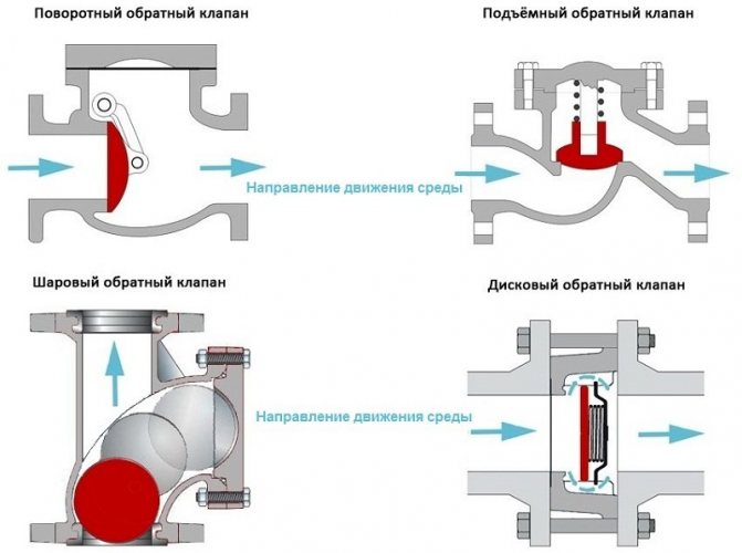
Varieties of check valves
There are valves installed using couplings and flanges. Some require special fittings, welding. Coupling mechanisms are threaded, easy to connect, such a unit is used on disc valves. Couplings are used to install fittings in an apartment or your own house.
Backlocking valves differ in design, operating conditions and purpose.
There are shutter devices:
- petal;
- disc type;
- ball varieties.
Ball
Poppet
Petal
Flange structures have additional parts with fastening holes and are connected to the line elements using bolts and nuts. The connection is robust and is used in large-diameter pipelines. Flanged devices are placed between the edges of the pipes, they are light and small in size. Welded valves are installed when the circuit is set with polypropylene pipes.
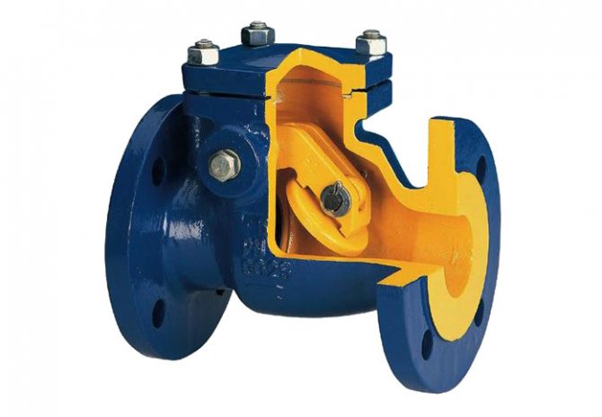
Petal
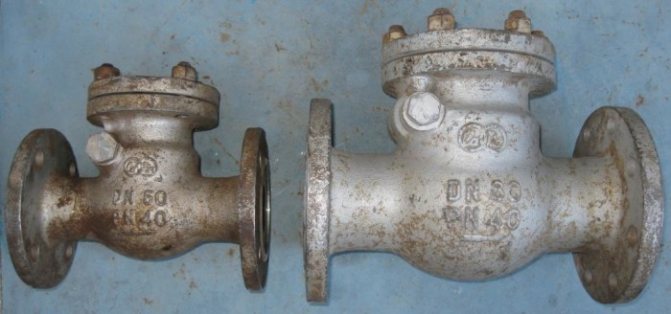
Varieties of Brass Lobe Check Valves
A thin steel plate serves as a breech block and is mounted on a hinged structure to provide a movable position.
The petal check valve for heating is available in two types:
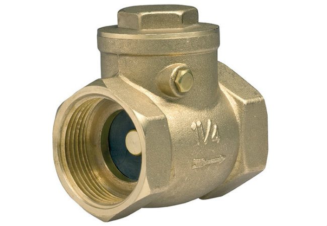
- swivel or single-leaf;
- bivalve.
In the first variety, there is one plate that revolves around the center line. The sash rises when the coolant moves in a given direction. The through hole is closed by a lowered part on a spring during reverse flow. Double-leaf devices are equipped with two locking plates fixed on the central axis and located in the opening passage.
Petal species have advantages:
- some valves do not have springs, these types are used in natural gravitational systems (gravity);
- devices are inexpensive.
The downside is that the double-leaf type impedes the flow of liquid, therefore it is used only in high-pressure lines.
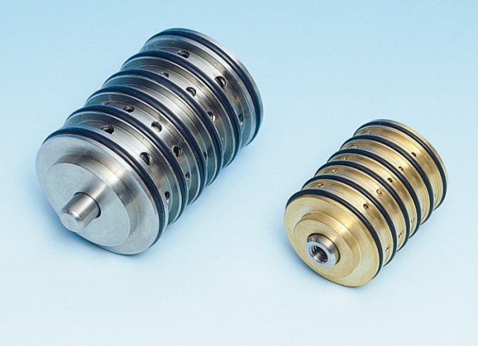
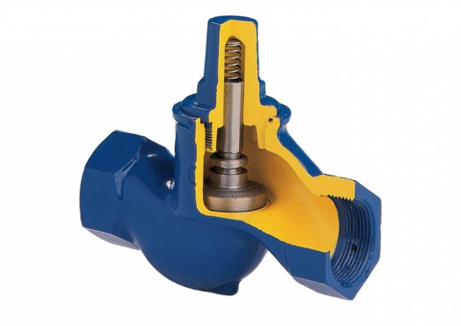
Disc type products
The principle of operation of the poppet check valve in the system
The shutter is made in the form of a disc made of metal or plastic. The element shuts off the fluid flow if the energy carrier changes direction. The disc is mounted on a spring, which is in a compressed position during forward movement. A change in direction leads to a straightening of the part and a change in the position of the locking disc. The design has a seal for a tight fit of the shutter, such a part completely eliminates leakage.
The advantages of disc valves for home heating schemes:
- small dimensions and low weight allow the use of mechanisms on contours of small diameter;
- the device does not require periodic technical inspection and repair;
- the device has a low price.
The disadvantage is the impossibility of repairing the poppet valve, so replacement is required. The mechanism creates resistance to flow and is not used in geothermal pump applications. Salt sediment is deposited on the disc, the device stops working.
When closed, a standard heating clapper valve creates a water hammer in the system. Disc valves with a soft closing mechanism have been developed, which have a higher cost.
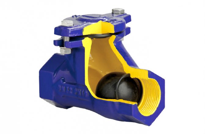
Ball valves
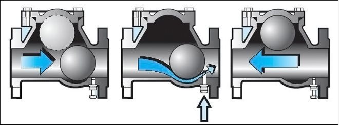
The operating principle of the ball check valve
The shutter mechanism is made in the form of a ball made of aluminum or other metals. The element is covered with rubber for a longer service life. The ball rises when the water flow moves in the correct direction and is located at the top of the valve. The energy carrier does not flow in the opposite direction, since the element goes down and blocks the hole.
Ball Valves Advantages:
- the structure works reliably, since the structure does not provide for rubbing and moving parts;
- there is a cover at the top of the mechanism for inspection or repair;
- the device does not create water hammer in the system when the ball moves.
The disadvantages include a large diameter, due to which ball valves are used in highways of significant diameters, and connection to household heating networks is not always appropriate.
Increase in temperatures
Another factor is the difference between the density of cold and hot water. Let's note the following fact - heating with natural circulation belongs to the self-regulating type. Thus, if the temperature of water heating is increased, then its flow rate changes and the circulating head becomes higher.
Strong heating of the liquid contributes to a much faster circulation. But this only happens in a cold room: when the air temperature in them reaches a certain mark, the batteries will cool down much more slowly.
The density of both the water heated in the boiler and the water that has already entered the radiators will practically be equal. The head will decrease, the rapid circulation of water will be replaced by measured circulation within the system.
As soon as the temperature of the premises of a private house drops to a certain level again, this will serve as a signal to increase the pressure. The system will try to equalize the temperature conditions. To do this, you will have to restart the fast circulation process. This is where the ability for self-regulation comes from.
In short, the rule is as follows - a one-time change in temperature and volume of water allows you to get the required heat output from batteries for heating rooms.
As a result, comfortable temperature conditions are maintained.
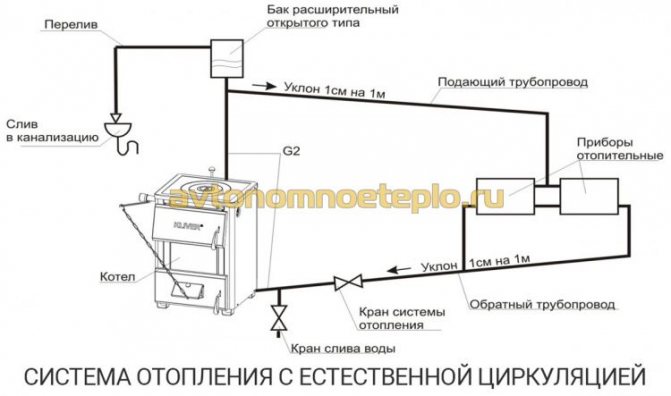
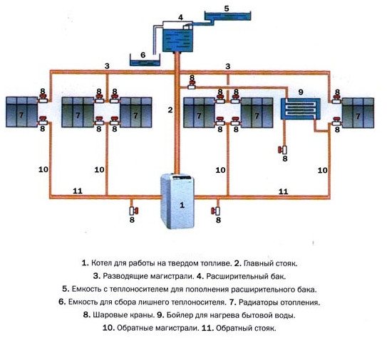
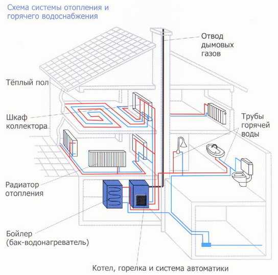
Scheme of action
The hot water heating system includes a boiler (water heater), return and supply pipelines, as well as heating equipment, an expansion tank and a safety valve. The liquid heats up to the desired temperature in the boiler and rises into the supply pipe and risers due to expansion.
From there, it goes into heating equipment - batteries and radiators, to which it gives off some of the heat. Then the return pipe directs the water to the boiler, where it heats up again to the set temperature. The cycle repeats as long as the system is operational.
It is important to remember that horizontal pipes are mounted with a slope in relation to the movement of the working environment.
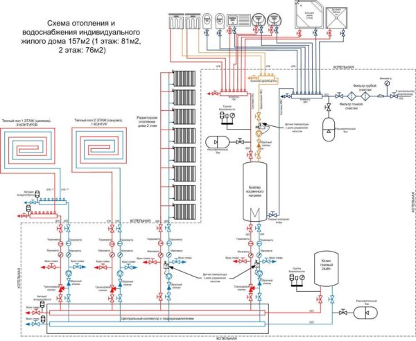
Design of forced circulation heating
Detailed home heating scheme
The primary task in the independent installation of water heating with a circulation pump is to draw up the correct diagram. To do this, you need a house plan, on which the location of pipes, radiators, valves and security groups is applied.
System calculation
At the stage of drawing up the diagrams, it is necessary to correctly calculate the pump parameters for the forced heating system of a private house. To do this, you can use special programs or do the calculations yourself. There are a number of simple formulas to help you calculate:
Where Рн is the rated power of the pump, kW, р is the density of the coolant, for water this indicator is 0.998 g / cm³, Q is the level of the coolant consumption, l, N is the required pressure, m.
Example program for calculating heating
To calculate the pressure indicator in the forced heating system of a house, it is necessary to know the total resistance of the pipeline and heat supply as a whole. Alas, it is almost impossible to do it yourself. To do this, you should use special software packages.
Having calculated the resistance of the pipeline in a hot water heating system with circulation, you can calculate the required pressure indicator using the following formula:
Where H is the calculated head, m, R is the resistance of the pipeline, L is the length of the largest straight section of the pipeline, m, ZF is the coefficient, which is usually 2.2.
Based on the results obtained, the optimal model of the circulation pump is selected.
If the calculated pump power indicators for a self-installed forced circulation heating system are large, it is recommended to purchase paired models.
Heating installation with circulation
Example of concealed installation of collector heating
Based on the calculated data, pipes of the required diameter are selected, and shut-off valves to them. However, the diagram does not show the way of installing the trunk. The pipelines can be installed in a hidden or open way. The first is recommended to be used only with full confidence in the reliability of the entire heating system of a private cottage with forced circulation.
It must be remembered that the quality of the components of the system will determine its performance and performance. This is especially true for the material of manufacture of pipes and valves. In addition, for a two-pipe heating system with forced circulation, it is recommended to heed the advice of professionals:
- Installation of an emergency power supply for the circulation pump in the event of a power outage;
- When using antifreeze as a coolant, check its compatibility with the materials for the manufacture of pipes, radiators and boiler;
- According to the heating scheme of a house with forced circulation, the boiler should be located at the lowest point of the system;
- In addition to the pump power, it is necessary to calculate the expansion tank.
Circulation heating installation technology is no different from the standard
It is important to take into account the features of the contour house - the material for making the walls, its heat losses. The latter directly affects the power of the entire system.
Analytics of the parameters of heating systems with forced circulation will help to form an objective opinion about it:
What is PVC-U?
Unplasticized solid polyvinyl chloride (PVC-U), otherwise called vinyl plastic, is labeled as PVC-U. It is produced without the use of plasticizers, therefore its density is 1.35-1.43 t / m3, and its thermal conductivity is 0.147 W / m ° C. Other technical properties of PVC-U:
- The highest level of tensile strength at 23 ° C is 53 MN / m2.
- Temporary resistance - 45 MPa.
- The elasticity index is 3060 MPa.
- The specific work of rupture is 55 MN / m2.
- The specific gravity is 1.41 g / cm3.
- Softens at 77 ° C.
- Specific heat - 0.84-2.1 J / g.
PVC-U is ideal for the manufacture of products that will be used in the transportation of liquids with temperatures from 1 to 60 ° C (strictly not recommended for use at temperatures above 65 ° C). Due to its dielectric properties, it is still actively used in insulating conductive parts of equipment.
Types of PVC-U pipes:
- For pressurized water supply. Single-layer gray products, mainly with a socket installation method.
- For external abduction. Three-layer products painted in a red shade, also with socket mounting method.
- For wells. Monolithic blue pipes with socket-threaded installation method.
Scope of pipes made of unplasticized polyvinyl chloride
The areas of use of these pipes and fittings are very versatile. They can be used not only for water supply, sewerage, water treatment and water purification, but also for the construction of greenhouses, irrigation, wells, swimming pools. They are also chosen when creating the production of acids, pulp and paper products, drinks, fertilizers. It's all about their unique resistance to salts, alkalis, acids, solvents and other chemically active substances. Due to the minimum hydraulic resistance and ease of installation, PVC-U pipes are also used in galvanic production, oil refining, metallurgical and coal industries. Because the adhesives are absolutely environmentally friendly, they are suitable for working with pipes through which potable water flows (potable water supply and water treatment systems).
Consumers choose PVC-U products for:
- Guaranteed 100% tightness.
- Compatible with other pipes.
- Resistance to any aggressive influences, including corrosion and decay.
- Service life over 50 years.
- Possibility of placement, both outdoors and indoors.
What it is
If a system with forced circulation requires a pressure difference created by a circulation pump or provided with a connection to a heating main, then the picture is different. Natural circulation heating uses a simple physical effect - the expansion of the liquid when heated.
If we ignore the technical subtleties, the basic scheme of work is as follows:
- The boiler heats up a certain amount of water. So, of course, it expands and, due to the lower density, is displaced upward by the colder mass of the coolant.
- Having risen to the top point of the heating system, the water, gradually cooling down, traces a circle around the heating system by gravity and returns to the boiler. At the same time, it gives off heat to heating devices and by the time it is again at the heat exchanger, it has a higher density than at the beginning. Then the cycle is repeated.
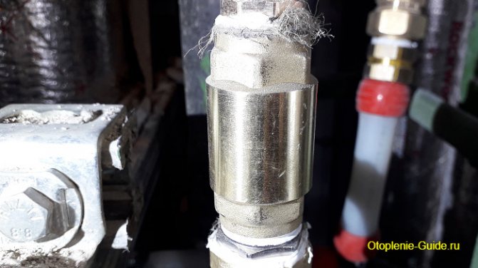
Useful: of course, nothing prevents you from including a circulation pump in the circuit. In normal mode, it will provide faster water circulation and uniform heating, and in the absence of electricity, the heating system will operate with natural circulation.
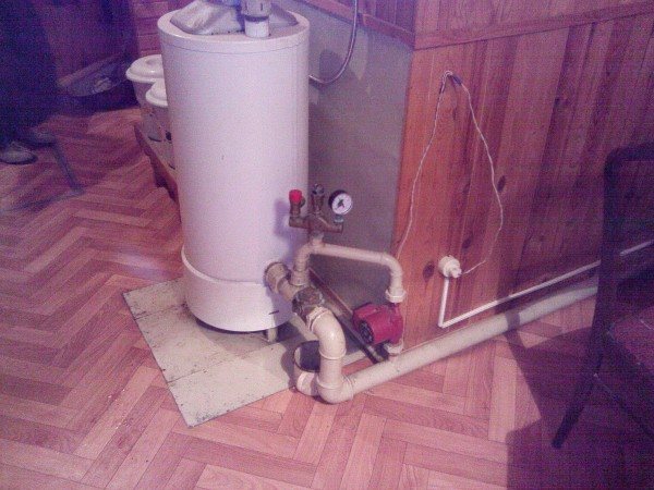
Pump operation in a natural circulation system.
The photo shows how the problem of interaction between the pump and the natural circulation system is solved. When the pump is running, the check valve is activated and all the water flows through the pump. It is worth turning it off - the valve opens, and water circulates through the thicker pipe due to thermal expansion.
Where is installed in the heating system
The general purpose of a check valve is to allow the coolant flow to flow in one direction and prevent it from moving back. No power supply or any other conditions are required for operation, they work from the movement of liquids. A check valve is installed for heating in all positions where counterflow and parasitic circuits are possible.
In a heating system with several branches, a check valve is placed on the return pipeline. This prevents the pump from "pushing" the flow in the opposite direction.
The same devices are placed in cold and hot water pipes. Designed for heating are distinguished by the fact that materials are used that tolerate long-term exposure to high temperatures. If there are rubber gaskets, then heat-resistant rubber is used. The same goes for plastic parts.
Speaking specifically about heating systems (CO), the check valve is installed:
- To a bypass with a circulation pump in the piping of a solid fuel boiler - to ensure the operation of the system in gravity mode (with natural circulation). In this case, the models with the lowest resistance are installed, which work easily and quickly - immediately when the flow from natural circulation appears. The function of the valve, in this case, is not to bypass the heating medium when the pump is running.
- On the return pipe when installing an indirect heating boiler. Why install a check valve in this case? In order to exclude the passage of the coolant in the opposite direction during operation of the circulation pump.
- With a branched heating system (for example, on several floors), on each branch. These check valves do not allow the coolant to "pull" if one of the branches is turned off (when using one circulation pump).
- On the make-up line of the system with cold water. Here, in addition to the shut-off valve, the reverse is also necessary. Since sometimes the pressure in the water supply is lower than in the heating system. Then, by opening the tap to feed the system, without a check valve, the coolant will "go" into the water supply system.
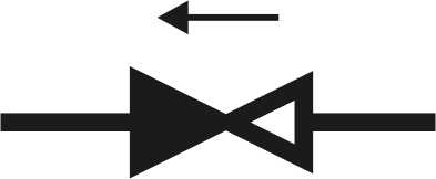
Check valve symbol in the diagram
In the diagrams, a check valve is indicated as two triangles directed with their vertices to one another. One of the triangles is filled in. The installation location in the branch is almost any. The main thing is to have it. The direction of flow is indicated by an arrow on the body. In this direction, the coolant passes. In the opposite, it overlaps. When installing, carefully follow the arrow (you can still focus on the locking element).
Boiler for gravity systems
Since such circuits are mainly needed for a heating device independent of electricity, the boilers must also operate without the use of electricity. These can be any non-automated units, except for pellet and electric ones.
Most often, solid fuel boilers work in systems with natural circulation. They are all good, but in many models the fuel burns out quickly. And if there are severe frosts outside the window, and the house is not sufficiently insulated, then in order to maintain an acceptable temperature at night, you have to get up and throw up fuel. This situation is especially common where firewood is used. The way out is to buy a long-burning boiler (non-volatile, of course). For example, in Lithuanian solid fuel boilers Stropuva, under certain conditions, firewood burns for up to 30 hours, and coal (anthracite) for up to several days. The characteristics of the Sandle boilers are slightly worse: the minimum burning time for firewood is 7 hours, for coal - 34 hours. The German company Buderus, the Czech Viadrus and the Polish-Ukrainian Wikchlach, as well as the Russian ones, Ogonyok, have boilers without automation and pumps.
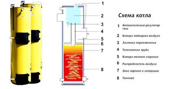
Non-volatile long-burning boiler Stropuva
There are Russian-made non-volatile gas boilers, for example, "Conord". which are produced in Rostov-on-Don. They can be used in natural circulation systems. The same plant produces non-volatile universal boilers "Don", which are also suitable for operation without electricity. Floor-standing gas boilers of the Italian company Bertta - model Novella Autonom and some other units of European and Asian manufacturers operate in systems with natural circulation.
The second way, which will help to increase the time between fireboxes, is to increase the inertia of the system. For this, heat accumulators (TA) are installed. They work well with solid fuel boilers, which do not have the ability to regulate the intensity of combustion: excess heat is diverted to a heat accumulator, in which energy is accumulated and consumed as the coolant in the main system cools.The connection of such a device has its own characteristics: it must be located on the supply pipeline at the bottom. Moreover, for efficient heat extraction and normal operation, it is as close to the boiler as possible. However, this solution is far from the best for gravitational systems. They slowly enough go to the normal circulation mode, but they are self-regulating: the colder it is in the room, the more the coolant cools down passing through the radiators. The greater the difference in temperatures, the more the density difference is obtained and the faster the coolant moves. And the installed TA makes the heating more inertial, and it takes much more time and fuel to accelerate. True, the heat is given off longer. In general, it's up to you to decide.
To stabilize the temperature in the system, a heat accumulator is installed
About the same problems with natural circulation stove heating. Here the role of the heat accumulator is played by the furnace array itself and it also requires a lot of energy (fuel) to accelerate the system. But in the case of using TA, the possibility of its exclusion is usually provided, and in the case of a furnace, this is unrealistic.
Options for working wiring diagrams
Heating systems are very diverse and the presence of a check valve is not required in all. Let's consider several cases when its installation is necessary. First of all, a check valve must be installed on each of the individual circuits in a closed circuit, provided that they are equipped with circulation pumps.
Some craftsmen strongly recommend installing a spring-type check valve in front of the inlet pipe of the only circulation pump in a single-circuit system. They motivate their advice by the fact that this way the pumping equipment can be protected from water hammer.
This is in no way true. Firstly, installing a check valve in a single-circuit system is hardly justified. Secondly, it is always installed after the circulation pump, otherwise the use of the device loses all meaning.
For multi-circuit systems, a reverse-acting shut-off device is vital. For example, when two boilers are used for heating, electric and solid fuel, or any others.
When one of the circulation pumps is turned off, the pressure in the pipeline will inevitably change and a so-called parasitic flow will appear, which will move in a small circle, which threatens trouble. It is impossible to do without shut-off valves here.
A similar situation occurs when using an indirect heating boiler. Especially if the equipment has a separate pump, if there is no buffer tank, hydraulic arrow or distributor comb.
Here, too, there is a high probability of a parasitic flow, to cut off which a check valve is needed, which is used specifically for arranging a branch with a boiler.
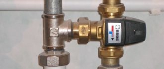
It is obligatory to use shut-off valves in systems with a bypass. Such schemes are usually used when converting a scheme from gravitational fluid circulation to forced circulation.
In this case, the valve is placed on the bypass parallel to the circulation pumping equipment. It is assumed that the main mode of operation will be forced. But when the pump is turned off due to a lack of electricity or a breakdown, the system will automatically switch to natural circulation.
This will happen as follows: the pump stops supplying the coolant, the check valve control unit stops experiencing pressure and closes.
Then the convection movement of the liquid along the main line resumes. This process will continue until the pump starts working. In addition, experts suggest installing a check valve on the make-up pipeline.This is optional, but highly desirable, since it avoids emptying the heating system for a variety of reasons.
For example, the owner opened a valve on the make-up line to increase the pressure in the system. If, by an unpleasant coincidence, at this moment the water supply is shut off, the coolant will simply squeeze out the rest of the cold water and go into the pipeline. As a result, the heating system will remain without liquid, the pressure in it will drop sharply and the boiler will stop.
In the above schemes, it is important to use the correct valves. To cut off parasitic flows between adjacent circuits, it is advisable to install disc or petal devices. In this case, the hydraulic resistance will be lower for the last option, which must be taken into account when choosing.
For the arrangement of the bypass assembly, it is preferable to choose a ball valve. This is due to the fact that it gives almost zero resistance. A disc-type valve can be installed in the make-up line. It should be a model with a fairly high working pressure.
Thus, the check valve may not be installed in all heating systems. It is necessarily used when arranging all types of bypasses for boilers and radiators, as well as at branch points of pipelines.
From the laws of physics
Suppose that in radiators and a boiler, the temperature of the liquid changes in jumps along the central axes: the upper parts contain hot liquid, and the lower ones contain cold liquid.
Hot water is less dense, which reduces its weight compared to cold water. As a result, the heating system consists of two communicating vessels, closed with each other, in which liquid moves from top to bottom.
A high pillar, formed by cooled water with a large weight, upon reaching the radiators, pushes the low pillar. As a result, the hot liquid is pushed and circulation occurs.
Types of gravity circulation heating systems
Despite the simple design of a water heating system with self-circulation of the coolant, there are at least four popular installation schemes. The choice of the type of wiring depends on the characteristics of the building itself and the expected performance.
To determine which scheme will work, in each individual case it is required to perform a hydraulic calculation of the system, take into account the characteristics of the heating unit, calculate the pipe diameter, etc. Professional help may be required when performing calculations.
Closed system with gravity circulation
In the EU countries, closed systems are the most popular among other solutions. In the Russian Federation, the scheme has not yet received widespread use. The principles of operation of a closed-type water heating system with a pumpless circulation are as follows:
- When heated, the coolant expands, water is displaced from the heating circuit.
- Under pressure, the liquid enters the closed diaphragm expansion tank. The design of the container is a cavity divided into two parts by a membrane. One half of the reservoir is filled with gas (most models use nitrogen). The second part remains empty for filling with a coolant.
- When the liquid is heated, enough pressure is created to push the membrane and compress the nitrogen. After cooling down, the reverse process takes place, and the gas squeezes the water out of the tank.
Otherwise, closed-type systems work like other natural circulation heating schemes. The disadvantages are the dependence on the volume of the expansion tank. For rooms with a large heated area, you will need to install a spacious container, which is not always advisable.
Open system with gravity circulation
The open-type heating system differs from the previous type only in the design of the expansion tank.This scheme was most often used in older buildings. The advantages of an open system are the ability to independently manufacture containers from scrap materials. The tank usually has a modest size and is installed on the roof or under the ceiling of the living room.
The main disadvantage of open structures is the ingress of air into pipes and heating radiators, which leads to increased corrosion and rapid failure of heating elements. Airing the system is also a frequent "guest" in open-type circuits. Therefore, radiators are installed at an angle; Mayevsky taps are required to bleed air.
One-pipe system with self-circulation
This solution has several advantages:
- There is no pair piping under the ceiling and above the floor level.
- Funds are saved on installation of the system.
The disadvantages of this solution are obvious. The heat transfer of heating radiators and the intensity of their heating decreases with distance from the boiler. As practice shows, a one-pipe heating system of a two-story house with natural circulation, even if all slopes are observed and the correct pipe diameter is selected, is often altered (by installing pumping equipment).
Self-circulation two-pipe system
The two-pipe heating system in a private house with natural circulation has the following design features:
- The supply and return pass through different pipes.
- The supply line is connected to each radiator through an inlet branch.
- The second line connects the battery to the return line.
As a result, a two-pipe radiator-type system offers the following advantages:
- Even distribution of heat.
- No need to add radiator sections for better heating.
- It is easier to adjust the system.
- The diameter of the water circuit is at least one size smaller than in single-pipe circuits.
- Lack of strict rules for installing a two-pipe system. Small deviations with respect to slopes are allowed.
The main advantage of a two-pipe heating system with lower and upper wiring is simplicity and, at the same time, efficiency of the design, which makes it possible to neutralize errors made in calculations or during installation work.
How the device works
An air valve (or several) is installed in the heating system, in places most likely for the accumulation of air bubbles. This prevents the formation of a large congestion, the heating works smoothly.
We recommend that you familiarize yourself with: Flange adapter for connecting PE pipes
Mayevsky crane
Such devices were named after the name of their developer. The Mayevsky crane has a thread and dimensions for a pipe with a diameter of 15 mm or 20 mm. It is arranged simply:
- In the body of the valve body, 2 through holes are made, which, in the open position of the Mayevsky crane, communicate with the heating system.
- These holes are sealed with a taper threaded screw.
- Air is discharged through a small (2 mm) opening directed upwards.
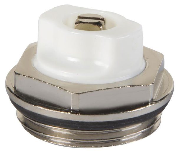
In order to bleed air from the system, unscrew the screw 1.5-2 turns. Air blows out with a whistle as communications are under pressure. The end of the airlock outlet is characterized by a drop in pressure and the appearance of water.
Note! The Mayevsky crane is a simple and reliable device for bleeding air accumulations. It does not clog or break because it has no moving parts. Its design is simple and reliable.
On the market, you can find several varieties of the Mayevsky crane, which are the same in design, but differ in the way of adjusting the locking screw. There are:
- with a comfortable handle for unscrewing by hand;
- with a regular head for a flat screwdriver;
- with a square head for a special key.
For an adult, the principle of unscrewing the locking screw does not matter.However, in a home with children, it is safer to use devices that must be unscrewed with a special device. Having unscrewed the usual tap with a comfortable handle, the child can scald with boiling water.
Automatic faucet
The automatic air relief valve is based on the principle of a float chamber, the design includes:
- vertical case with a diameter of 15 mm;
- float inside the body;
- a spring-loaded valve with a cover, which is connected and regulated by a float.
The automatic air valve for the heating system works without human intervention. Normally, when there is no air in the system, the float is pressed against the valve cover by the pressure of the liquid filler. At the same time, the lid is tightly closed.
We recommend that you familiarize yourself with: Fittings for installing a heating system
As air accumulates in the valve body, the float goes down. As soon as it drops to the critical level, the spring valve opens and bleeds out the air. Under the pressure of the carrier in the system, the space is again filled with liquid. The float rises to close the spring valve cover.
When there is no coolant in the communications, the float lies at the bottom of the valve. As the system fills, air leaves the tap in a continuous flow until the coolant reaches the float.
Note! A small amount of air is constantly present under the cover of the automatic valve. This is normal and does not affect work in any way.
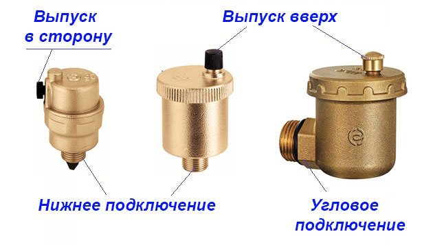
A distinction is made between the following configurations of automatic air valves for heating:
- with vertical air discharge;
- with lateral air discharge (through a special jet);
- with bottom connection;
- with corner connection.
For the layman, the design features of an automatic crane do not matter. However, for a professional, there is a difference in choosing between devices.
It's believed that:
- a device with a nozzle and a side hole is more reliable in operation than an automatic valve with a vertical air discharge;
- The bottom-connected valve is more effective at trapping air bubbles than the side-mounted valve.
If the design of the Mayevsky crane has not undergone changes for many years, then the device of automatic valves is constantly being improved and supplemented.
Manufacturers offer automatic valves with additional devices:
- with a membrane to protect against water hammer;
- with a shut-off valve, for the convenience of dismantling the device during the heating season;
- mini valves.
Note! The disadvantage of an automatic valve is that it gets dirty quickly. Limescale, debris clog the internal, moving parts of the device. This leads to a weakening of the efficiency of its work or complete failure.
Automatic air valves for heating need frequent inspection and cleaning. The undoubted advantages of these devices include the ability to install them in hard-to-reach places.
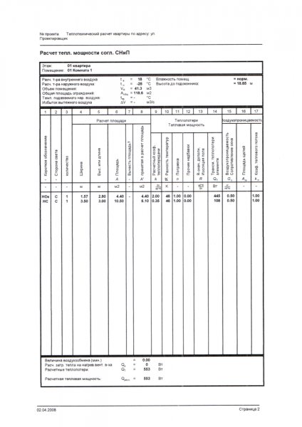
Power calculation
The effective heat output of the boiler is calculated in the same way as in all other cases.
By area
The simplest way is the calculation of the area of the room recommended by SNiP. 1 kW of thermal power should fall on 10 m2 of the area of the room. For the southern regions, a coefficient of 0.7 - 0.9 is taken, for the middle zone of the country - 1.2 - 1.3, for the regions of the Far North - 1.5-2.0.
Like any rough calculation, this method neglects many factors:
- The height of the ceilings. It is far from being the standard 2.5 meters everywhere.
- Heat leaks through the openings.
- The location of the room inside the house or against external walls.
All calculation methods give large errors, therefore, the thermal power is usually included in the project with a certain margin.
By volume, taking into account additional factors
A more accurate picture will be given by another calculation method.
- The basis is a thermal power of 40 watts per cubic meter of air volume in the room.
- Regional coefficients apply in this case as well.
- Each standard size window adds 100 watts to our estimate. Each door is 200.
- The location of the room against the outer wall will give, depending on its thickness and material, a coefficient of 1.1 - 1.3.
- A private house with a street below and above is not warm neighboring apartments, is calculated with a coefficient of 1.5.
However: this calculation will be VERY approximate. Suffice it to say that in private houses built using energy-saving technologies, a heating capacity of 50-60 watts per SQUARE meter is included in the project. Too much is determined by heat leaks through walls and ceilings.
Advantages of installing a two-pipe system
When designing water heating with forced circulation for a private house, they choose, based on the material capabilities of the owner, a one-pipe or two-pipe scheme. The one-pipe system is cheaper, easier to install, and the two-pipe system is more efficient in operation. When installing a horizontal two-pipe heating system, three pipeline layouts are possible: dead-end, associated and collector.
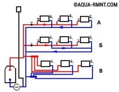
Three schemes for the device of a horizontal two-pipe heating system in a private house: A) dead-end; B) passing; B) collector (beam)
Immediately, we note that the latter has the greatest efficiency, namely, the collector piping. However, its implementation increases the consumption of materials, as well as the complexity of the installation work.
The nuances of competent installation
During the installation of valves, several rules should be strictly observed:
- The valve is installed strictly in the direction of the coolant flow. In order to avoid mistakes, there is always a marking on the product body in the form of an arrow indicating the working direction.
- Paronite gaskets can be used to seal the joints, provided they do not reduce the bore diameter. Otherwise, the valve will exert more hydraulic pressure than planned.
- The device must be installed so that other elements of the heating system do not exert additional pressure on its body.
- It is highly advisable to put a coarse mesh in front of the check valve. This will make it possible to prevent the ingress of solid particles into the locking mechanism, which, in turn, can lead to a violation of the tightness of the device when closed.
Another important point: before installation, you need to make sure once again that the valve is selected correctly.
For example, for schemes with forced circulation, any type of device is suitable, and for gravitational systems, only a rotary petal without a spring. Since the coolant moving by gravity will not be able to cope with the resistance of the spring.