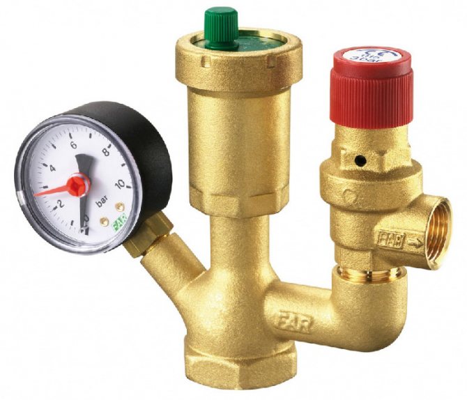
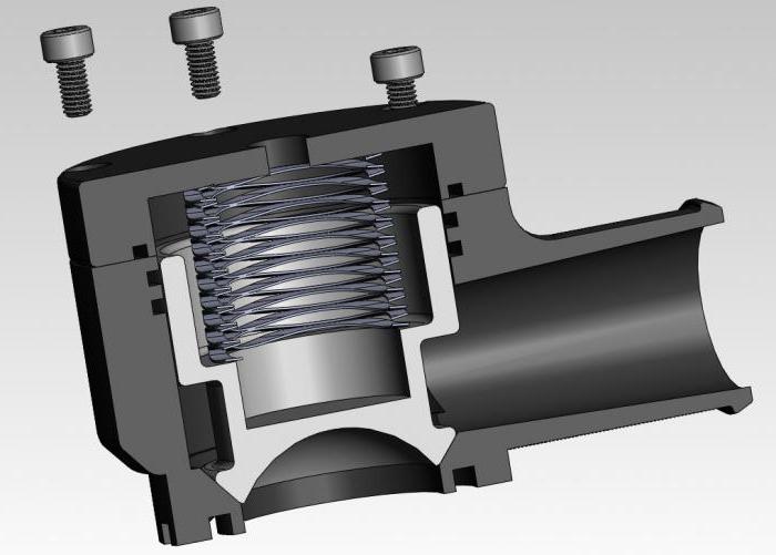
The bypass valve normalizes the pressure in the pipeline. The control valves redirect the energy carrier to an additional line circuit (bypass). The pressure of gas or liquid is maintained at the same level after the automatic release of surplus working medium. The valve plug opens when the pressure rises above the required value and closes when the pressure drops.
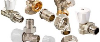
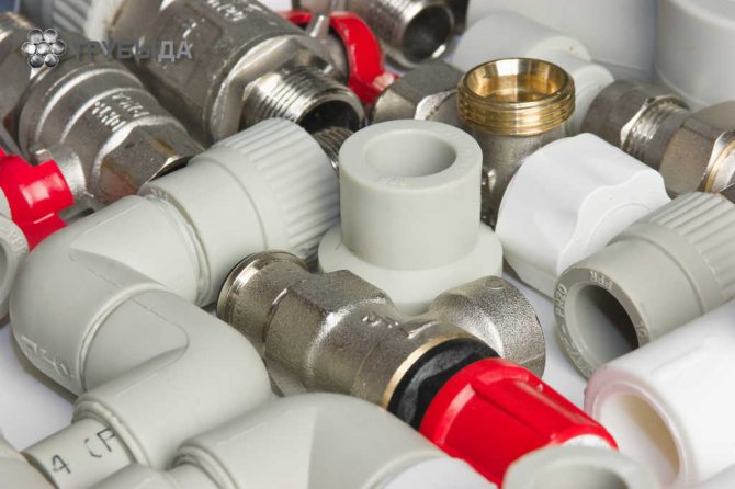
Overflow valve with fittings
What is it and what is it for
The volume of the coolant changes during operation. A change in pressure impairs the performance of the heating main. The pipes warm up unevenly, air accumulates in some areas, and the nodes become unusable. The pressure balance is maintained manually, but it is better to entrust the change in the amount of fuel to the automation, which requires a valve in the system.
Device Specifications:
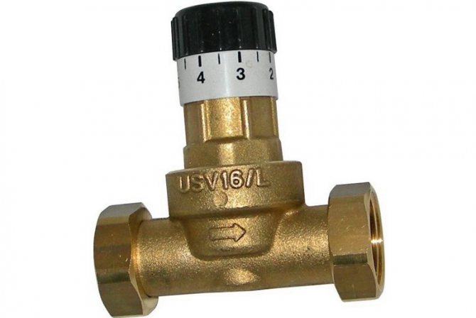
- DN is the nominal diameter of the connection nozzles. The value is used in the case of standardizing the typical sizes of manifold fittings. The actual DN may change slightly up or down. A similar characteristic was used in the post-Soviet period to designate the nominal diameter - Du.
- PN is the nominal size of the liquid or gas pressure at a temperature of + 20 ° C. The increase in pressure in the system remains within the standard limits, and the safety of operation is ensured. The characteristic was used in a similar designation Ru of automation in the post-Soviet period.
- Kvs is the coefficient of the ability to pass the volume of liquid when the heat carrier is heated to + 20 ° С. The decrease in pressure in the automation shows 1 bar. The coefficient is used in the calculations of hydraulic systems to identify pressure losses.
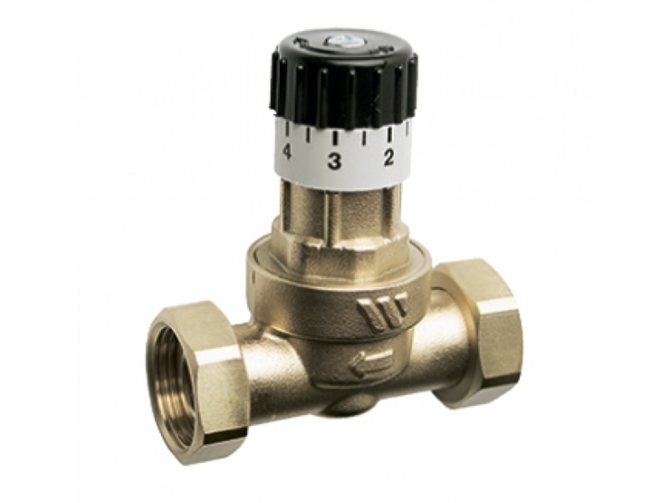
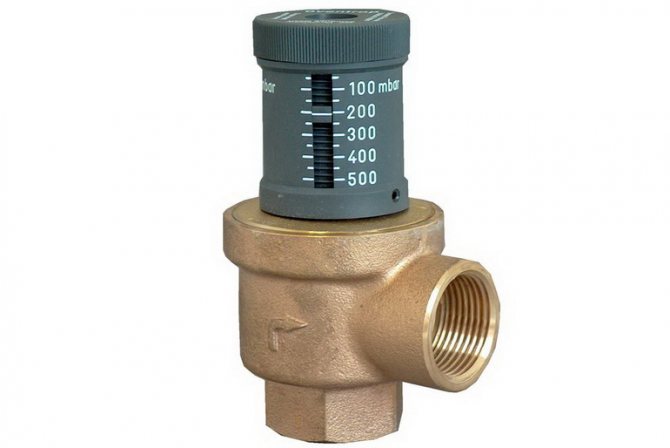
- The setting range is the difference in pressure change maintained by the automatic device. The indicator depends on the degree of spring elasticity.
Varieties of bypass valves
In order to determine the order of installation work and the selection of parts for radiators, it is necessary to be aware of the types and purpose of safety relief valves.
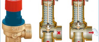
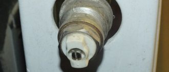
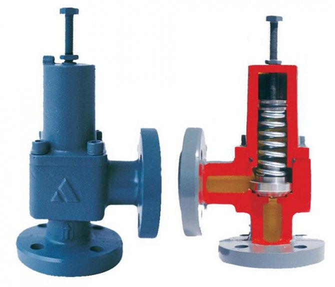
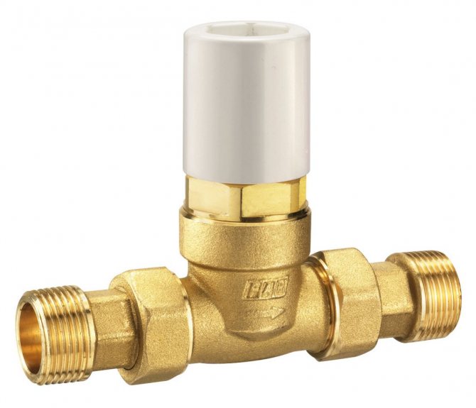
- Coupling fuses. These products are mechanisms with double-sided threads and a gasket on the outside. This part works with a spring that holds the stem. When you apply force on the rod, the passage will open. When pressure appears from the back side, due to blocking, it will increase. Such fuses are made of brass. The plate, which is located inside the stem, is made of heat-resistant plastic, and the spring is made of stainless steel. The mechanism functions due to the fact that, under pressure, water enters the flap, which rises, in turn, freeing movement for the flow. When the pressure decreases, the stem goes down, so flow back is not possible.
- Three-way valves. Such an element is designed to cool the coolant. Products with manual control, electric drive and servo drive are distinguished. Their design is quite simple, there are outgoing and incoming holes. The fluid flow is regulated by means of a special valve, which resembles a rod or a ball. When it rotates, the flow moves in the required direction. This valve is installed on circuits where the temperature regime is low. For example, in areas where batteries are adjacent to the warm floor, operating from a single heat source.
- Four-way valve. This product is usually made of bronze.It has three holes: two outlets and one inlet. A corrosion-resistant stem acts as a control element. When moving in the vertical direction, it does not completely shut off the water flow, which makes it possible to redistribute the flows.
Thus, it is not worth neglecting the installation of a bypass valve in the heating system.
Areas of use
Automation regulates the pressure in the return and supply circuits of the pipeline, intended for closed-type heating mains. The pressure is normalized when the radiator valves are closed and the heat load is reduced.
The valve provides operational advantages:
- reduces the load on the running pump;
- prevents the formation of rust inside the boiler;
- eliminates noise and hum in pipes;
- increases the degree of heating of the energy carrier in the return loop;
- reduces hydraulic losses.
Overflow valves are used in pipelines of varying complexity. An automatic valve is installed to stabilize the pressure:
- In multi-circuit heat supply systems. Energy consumption decreases when one of the pipeline branches is disconnected, which leads to an increase in the head power. Maintaining the pressure at the required level avoids collector breakthroughs and overloading the heat generating unit.
- In heating pipelines where temperature regulators are installed, and in hot water mains. The amount of heating medium increases or decreases when the liquid temperature is adjusted. It is required to restore the pressure balance in the pipeline branch.
- In water supply lines with installed storage water heaters. Volume changes from frequent hot water intake lead to imbalances. The bypass device is used to prevent breakdowns and accidents.
How is the automatic make-up valve of the heating system used
Since water is the main coolant in heating systems, during operation the liquid gradually loses its volume, that is, its amount decreases.
When the volumes of the coolant reach a critical value, the balance of the heating system is disturbed.
To prevent such deviations in the operation of the heating circuits, a special valve is used that normalizes the working pressure and ensures stability.
The operation of the heating system becomes more controlled and balanced if an automatic make-up valve for the heating system is installed. After all, it is too time-consuming to constantly use the valve to normalize the pressure in the heating system, and the user simply forgets about such types of adjustment, therefore, it would be preferable to install an automatic make-up valve.
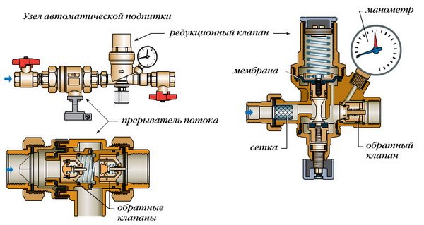
In addition, when using the valve, there is a real risk of an increase in the differential pressure, which will lead to an emergency and damage the heating equipment. And another negative phenomenon when using a manual increase in the supply of the coolant is air bubbles that seep into the heating system. Thanks to the automatic make-up valve for the heating system:
- The pressure in the circuits is constantly monitored,
- The coolant enters the system in portions, without exerting additional load on the heat exchanger,
- No air leaks into the system.
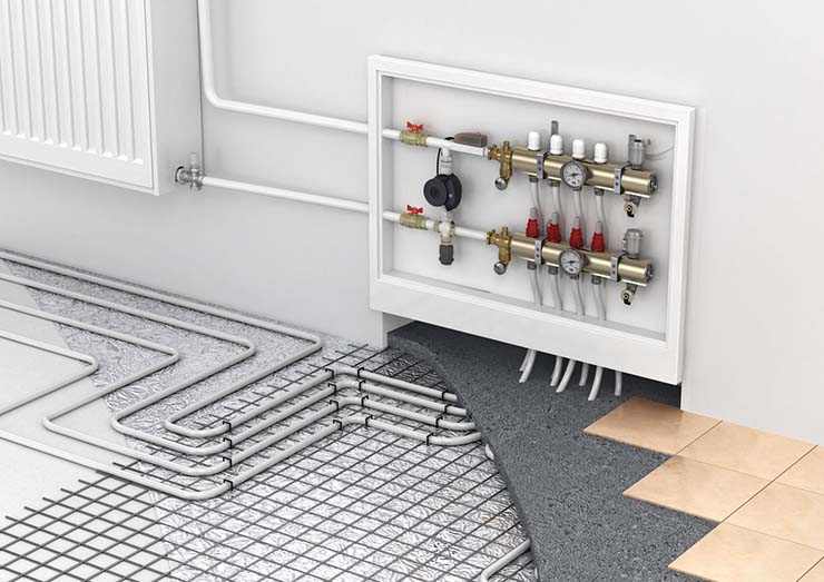
The heating system diagram should include not only heating equipment, but also additional elements that can ensure uninterrupted and stable operation.
More on this topic on our website:
- I choose floor heating radiators - water with a fan The floor design of heating equipment has its own subtleties, as well as a number of negative and positive aspects, which should be learned in more detail….
- Electric energy is actively used in the operation of the heating system, it is thanks to it that the coolant receives the required temperature and carries it along the pipelines. Designed to Significantly Improve Productivity ...
- Due to the constant changes in the temperature of the coolant in the heating circuits, an involuntary increase in the volume of water in the system occurs, and a special valve will become a reliable protection against this phenomenon. Let's try ...
- Definitely, starting with simple words, we can say something like the following - an electric boiler is extremely necessary nowadays. The reason, which is also an explanation, is very simple and consists in ...
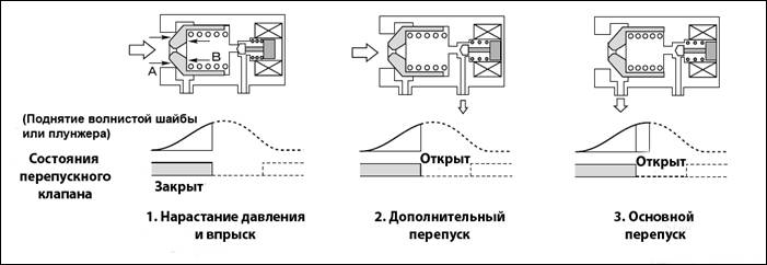
Principle of operation
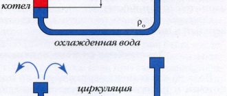
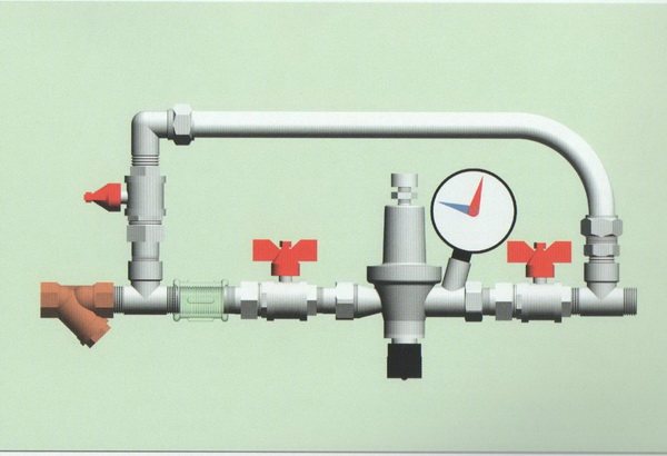
The automatic regulator is installed on an auxiliary line mounted after the pump or acceleration manifold. The bypass connects the drive circuit to the return collector. The liquid is also bypassed in the return flow if the heating boiler is part of the heating system, which is the principle of the bypass valve. Excess water is discharged to the external environment if the water heater operates in an autonomous line.
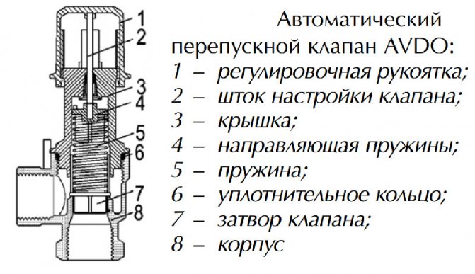
Bypass automation device:
- the damper is located in a metal case, a spring is also installed there;
- the handle is located on the body, it is designed to adjust the permissible pressure;
- temperature sensors cut in additionally, a device for replenishing and venting the energy carrier is provided.
The damper applies pressure to the spring, releasing the passage in the body. The flow is redirected from the feed to the outflow loop. The pressure is leveled, the indicators are maintained in this state. The spring expands and moves the damper in the opposite direction when the pressure decreases. The liquid does not flow into the bypass and the pressure is equalized under different operating conditions.
The straight-through valve is different from the pressure reducing device and safety automatics. The difference lies in the mechanism for reducing the pressure and the frequency of operation.
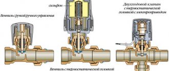
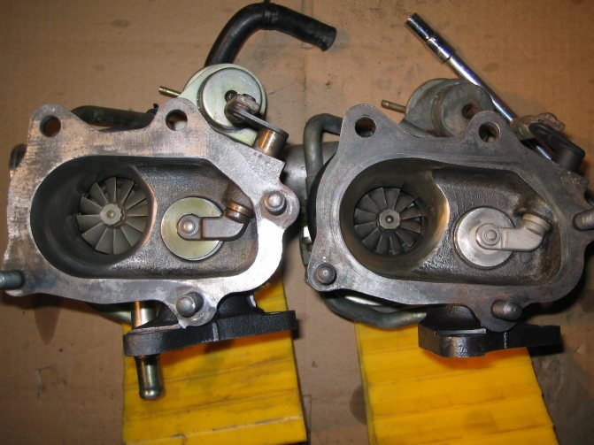
Wastegate draft adjustment
The lever itself moves freely, swinging on the mount. If it is not, and it does not move freely when disconnected from the control valve linkage, then there is some problem and something is interfering with it. This needs to be fixed.
Sometimes the lever jerks, especially when heated. The length of the actuator rod itself can be varied, thus adjusting the degree of open / close of the wastegate.
Tightening the end will shorten the pull of the control valve, relaxing it will lengthen it. If the thrust is shorter, the valve is tighter closed and the activator needs more pressure to open the valve.
The result is more pressure, faster cranking of the turbine, and the wastegate does not open as much or as quickly. And vice versa when the traction is weakened
If you are using a feedback controller that measures and controls the pressure itself (this is a common thing for electronic controllers), then adjusting the bypass valve thrust will not give the same effect as it does in the absence of feedback.
This is because the controller "takes into account" the changes that have occurred, so this adjustment will have little impact. In addition, a good electronic controller keeps the bypass valve closed (actuator pressure 0 psi) until the correct level is reached, so the pressure builds up much faster.
Types and designs
The device is produced in the form of indirect and direct mechanics.
The straight automatic machine has a simple internal structure. The damper operates from the pressure of the coolant.The device is used because of ease of use, insensitivity to dirt and reliability. Automation is characterized by reduced accuracy when setting the nominal values
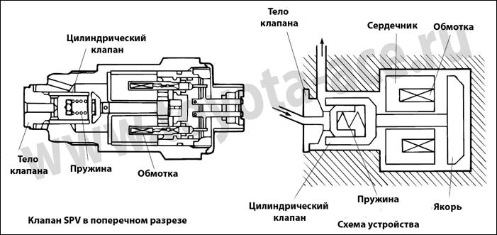
The indirect action automation contains a pressure sensor and two valves:
- main, moving from a piston drive;
- pulse, having a small diameter.
When the pressure in the line decreases, the smaller valve puts pressure on the piston, which causes the main flap to move. The throughput of the automatic device is regulated by an indirect method. The valves are more precise, but unreliable due to the many operating elements.
The systems use different heating devices. Each type requires a different overflow valve design:
- The direct valve is installed in electrical systems running on diesel or gas.
- Solid fuel units do not turn off quickly, smooth adjustment does not work. Valves are used that respond to changes in the temperature of the energy carrier and an increase in pressure. Automation is connected to the cold pipeline and external sewerage.
- The regulating handle is used in homes where the owner can independently set the allowable pressure.
- The auto valve is not used on open lines. The expansion vessel regulates the pressure in the network by compensation.
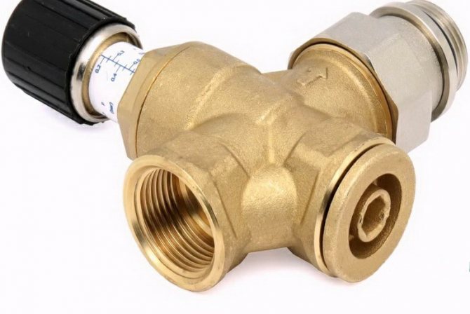
Specifications
The main values that determine the capabilities of the bypass devices in the system:
- Passage diameter. Internal section of the carrier passage through the valve. May differ from the diameter of the main circuit of the system.
- Bandwidth. It characterizes the volume of the working medium that can pass through the valve per unit of time at a nominal pressure of 1 atm. Measured in cubic meters / hour.
- Ultimate pressure. The maximum value of the excess head for which the operation of the device is designed. Exceeding this parameter in the system leads to displacement of the valve stem and the beginning of the media bypass. Determined at a carrier temperature of 20 ° C.
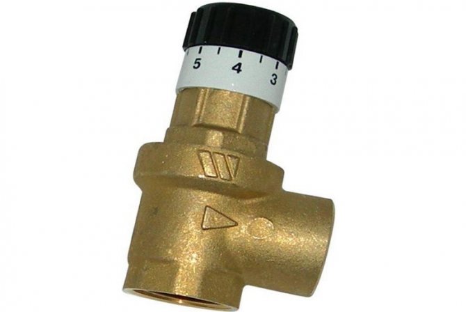
- Setting range. The limits of the possibilities of regulating the overpressure at which the valve begins to open. The unit of measurement is bar.

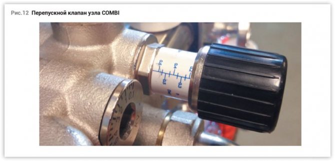
Adjustment scale with adjustment slide
Selection Tips
The overflow valves correspond to the performance of heat generators, have the appropriate capacity and allowable pressure. The branch pipes are connected without fittings; for this, their diameter is selected so as not to increase the vulnerability of the pipeline.
Overflow valves are sometimes sold complete with a water heater or heating unit, or the device is purchased separately, depending on the type of fuel and technical characteristics. The ability of the user to set up automation and set operating parameters is taken into account. The price plays a role only when choosing a model of the same type of devices with equal parameters, but differing in cost.
Installation
The valve is installed according to the inset guide. Tips for the correct installation of different types of automation:
- a strainer is installed in front of the overflow valve;
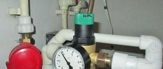
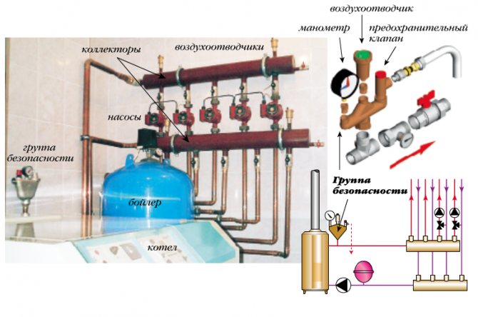
- manometers are mounted before and after the valve;
- the device is cut so that its body does not experience mechanical torsion, compression or tension loads associated with the operation of the connected circuit;
- it is better to choose and install automation with the organization of straight sections in front of the valve (5DN) and after it (10DN);
- the overflow device is mounted on pipes located horizontally, obliquely or vertically, if there are no other instructions on this in the instructions.
Automation is set up after starting water into the line during the adjustment of the entire unit. It is allowed to adjust the valve in an empty pipeline if there is a permissible value.
The auto valve is regulated by creating the required differential at the location of the device, the screw is rotated until the valve opens. The difference is reduced and the closing moment of the damper is monitored, and the device is additionally adjusted. The pressure changes smoothly due to the fact that each turn of the screw corresponds to a clear range of pressure change.
The operation of the valve is checked by varying the differential pressure at the installation site. The accuracy of regulation and the opening speed of the damper are checked. The error is allowed within 10% at the boundary values. The set pressure corresponds to the opening moment, full expansion is achieved at values of a higher differential head.
Maintenance is done once a month, the setting pressure is checked, the speed at which the damper starts to open. The function of the bypass valve is checked by changing the pressure at its location. The filter is cleaned depending on the degree of contamination, as evidenced by the readings of the manometers.
Where to mount and why
Defective vvti valve. Where is the VVTI valve and how to check it
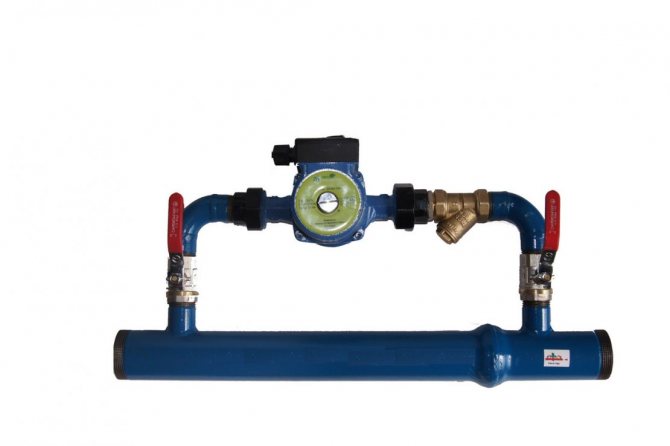
The thermostatic valve is mounted by tapping it into the system at a short distance from the pump supplying liquid, between the return line and the supply circuit. The mode of setting the maximum allowable pressure limit of the working medium allows the owner to make adjustments manually.
Currently, the range of these products offered by the retail network is quite large.
But as practice shows, it is better to pay attention to such well-known brands as Mankenberg, Valtec, DANFOSS. They have proven in practice efficiency, reliability and durability in work
Appointment
Thermostatic control bypass valves are designed to ensure a stable pressure difference between the return and supply pipes in closed heating systems. If the heat load is reduced, the thermostatic radiator valves are closed. This leads to an increase in the pressure drop between the return and supply lines.
The use of a bypass valve has the following advantages:
- reduces the load on the pump;
- protects the boiler from rust;
- prevents the occurrence of unnatural noises for normal operation;
- increases the temperature of the working medium in the return pipeline.
By closing the thermostatic valves on the radiators, we will get an increase in the resistance of our heating system (an increase in the pressure difference between the return and supply pipelines). This will increase the load on the pump and cause noise.
If the pressure reaches a maximum level that matches the setting of the bypass valve, it opens to form a regulated bypass. Also, the bypass valve is installed behind the circulation pump between the return and supply pipelines.