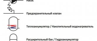
The device of boilers Vilant
Electrical diagram
Consider the design of the Vilant boiler using pictures and diagrams from the installation manual. For correct setup during installation and troubleshooting, a circuit diagram is required. It shows exactly where all the nodes of the device are connected to the electrical control board.
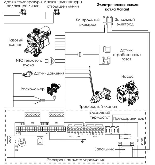
The wiring diagram for a specific model of a gas heater may differ slightly from the standard one. To make repairs and adjust a specific model, you need to use the instruction manual that comes with each device.
Hydraulic circuit
On the hydraulic diagram of the boiler operation, all the nodes that pass the liquid during the heating process are indicated. Below there are five pipes, two for hot water supply and heating and one for supplying gas.
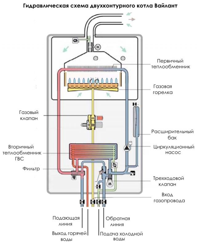
The cooled heat carrier from the heating system enters the rightmost branch pipe. The liquid passes through a three-way valve, a circulation pump and enters the primary heat exchanger. There it heats up and goes out through the filter from the leftmost branch pipe into the heating system. If hot water priority is set, then it passes through the secondary heat exchanger, while heating the water for domestic use. A three-way valve controls the flow direction of the heating medium.
Cold clean water enters the second pipe on the right side, goes to the secondary heat exchanger and from there, the already heated one goes into the second pipe from the left.
Page 60
EloBLOCK Installation and Maintenance Manual 0020094388_02
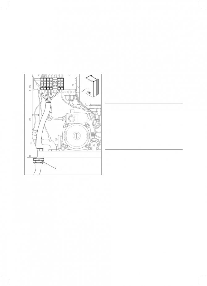
Electrical connection
Wall-mounted electric boilers Vaillant eloBLOCK are designed to be connected to a 3 x 230/400 V power supply. The VE 6 and VE 9 devices can be connected to 1 x 230 V by means of a jumper. The nominal voltage of each phase of the network must be 230 V; if the mains voltage is above 253 V and below 190 V, operational malfunctions are possible.
5.1 Mains connection (here: eloBLOCK VE 24, VE 28)
> Remove the front casing of the device.
> Fit the supplied bracket for the mains cable gland.
> Route the mains supply line through the cable gland (1)
left on the underside of the machine.
> Remove the sheathing from the mains supply line approx. on the
2 - 3 cm and strip the core insulation.
> Connect the connecting cable to the appropriate screw
terminals (¬
Fig. 5.2 - 5.4).
The conductors must be mechanically firmly anchored in
screw terminals of the cable entry.
> Refit the front casing.
Operation with a two-tariff electricity meter
Regular rate power supply may be interrupted during peak hours. In this case, heating mode is only possible during the low tariff period. The duration and frequency of energy supply at a low tariff is determined by the energy supplying organization or negotiated with it.
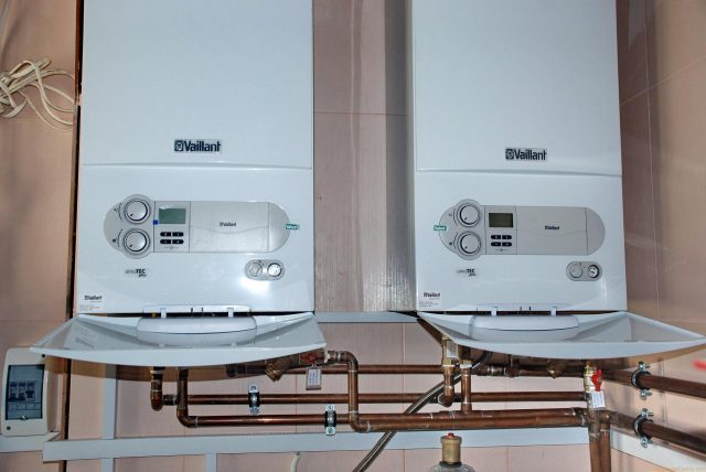
Features of one and two-circuit models
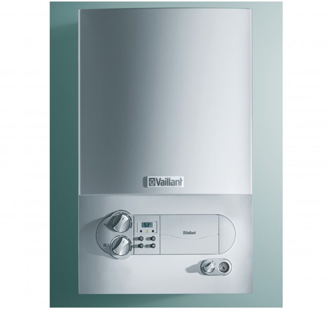
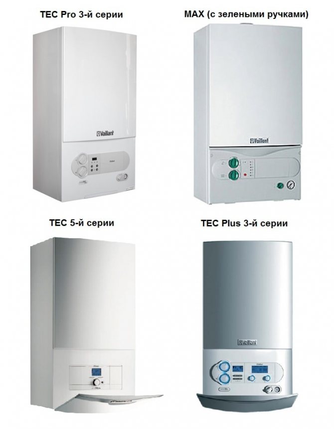
Single-circuit wall-hung boilers such as the Vaillant Turbotec plus VU are distinguished by their simple design and compactness. Their main disadvantage is that they do not provide the user with hot water supply. In order to use it to heat running water, you will have to additionally purchase and install an indirect heating boiler.
Vaillant Turbotec plus VU boilers
Dual circuit models such as the Vaillant 240 are equipped with a thin-walled steel secondary heat exchanger to transfer heat from the heating medium to the running water.
Also available are two-circuit devices with a built-in boiler. They are large in size. The water tank is located at the bottom of the case. This is how Vilant models such as AtmoCompact and AtmoVit Combi are arranged. Let's take a look at how a typical two-circuit boiler works.
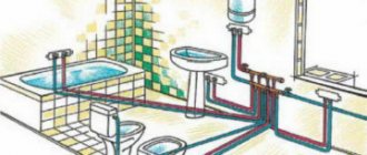
Connecting communications
The supply to the gas main and the installation of connections are carried out by representatives of the relevant services, since the norms for connecting a gas boiler provide for the performance of these works by organizations or persons with a special permit. It is not allowed to do this work with your own hands, you just need to purchase and legalize the meter, as well as buy a gas filter.
Another important step is to properly connect the gas boiler to the chimney. Units, the operation of which depends on natural draft, must be cut into a vertical shaft or attached to a vertical chimney with a height of at least 5-6 m. When installing the horizontal section of the chimney from individual elements, it is necessary to ensure that they enter one another in the direction of travel combustion products, and not vice versa. The tie-in into the vertical channel is carefully sealed with materials resistant to high temperatures.
Since the automation equipment, electric drives and the circulation pump that supply the vast majority of heaters are powered by electricity, it will be necessary to connect the gas boilers to the mains. There are no big difficulties here, it is important to correctly and safely supply electricity to the furnace room and install several sockets there. The requirements are simple:
- The sockets must be grounded, that is, 3 wires must be brought into the room, one of which is ground.
- Do not locate outlets near shut-off valves or safety valves.
- The insulation degree of the wires must be observed in accordance with the operating instructions for the heating equipment.
- Plugs or other sockets must be installed so that the plugged wires do not hang down and do not touch hot surfaces or equipment.
Do not forget about the dependence of the gas installation on electricity, especially when there are frequent outages in your area. In this connection, we recommend purchasing an uninterruptible power supply for the boiler. Otherwise, you run the risk of being left not only without light, but also without heat in the house.
Principle of operation
Consider the principle of operation of Vilant gas boilers. They are designed for space heating and domestic hot water heating. They are connected to a heating system with radiators located throughout the house. When the coolant inside cools down to a certain temperature, the thermostat is triggered. It sends a signal to the control board.
From there, a signal goes to turn on the circulation pump, open the gas valve and supply electricity to the ignition electrodes. Gas begins to burn in the burner, above which the main tubular heat exchanger is located. In it, heat is transferred from the combustion of the gas to the coolant in the tubes.
When the water in the heating system heats up to the temperature set in the settings, the thermostat is triggered again and the boiler stops working. When the hot water tap is turned on, a three-way valve is triggered, which directs the heated coolant to the secondary heat exchanger. There, through the thin walls, heat is transferred to the tap liquid.
In some series, for example, Vailllant Turbo, it is possible to connect an external room thermostat. In this case, you can adjust the heating to the desired room temperature.
Vailllant Turbo boilers
Condensing models such as Vilant ecoTEC have a specially designed heat exchanger that allows additional use of the heat of the volatile combustion products during their condensation.
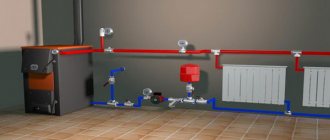
Forced circulation schemes
If there is a forced induction of the movement of the coolant in the network, then the previous piping scheme for a floor-standing gas boiler is supplemented with a circulation pump. As a rule, in networks with 1-2 branches, the pump is installed on the return line in front of the heater entrance, and it is recommended to install a mesh filter before it. In this case, the pipe diameters will be smaller, as well as the slopes (at least 2 mm per 1 m of the line). The expansion tank can be used closed and also connected to the return:
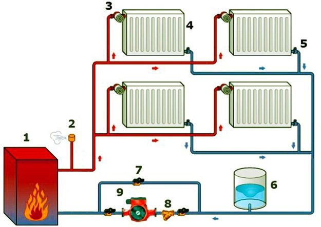
1 - floor gas heater; 2- safety relief valve; 3 - radiator thermostatic regulator; 4 - radiator; 5 - balancing valve; 6 - expansion tank; 7 - bypass with a ball valve; 8 - filter - mud collector; 9 - circulation pump.
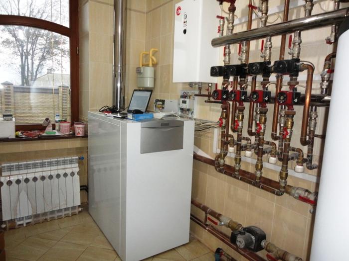
Many models of modern heating boilers are equipped with a built-in circulation pump, which simplifies their connection. In a situation where there are several different heating systems in the house (radiators, underfloor heating, an indirect water heating boiler), a piping scheme for a gas heating boiler with hydraulic division into circuits (hydraulic arrow) is recommended.
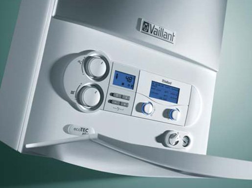
Scope of use and technical characteristics
Vailant gas boilers are designed for heating domestic and industrial premises. Depending on the model, they have a different power range. From small appliances like the 4 kW Eco Compact to higher power devices like the Eco Craft VKK 294 kW. Also, if necessary, a number of models can be connected in a cascade to fold the generated heat energy.
Both wall-mounted and floor-standing devices are available. Depending on the type of combustion chamber, atmospheric and turbocharged series are produced. For example, Vilant T3 and T4, where T3 is equipped with atmospheric, and T4 is equipped with a closed combustion chamber. The heat exchanger is made of copper, stainless steel or cast iron.
All devices are equipped with modern protection devices: from freezing, overheating, extinguishing the flame and lack of draft. Individual devices can operate on both natural and liquefied gas. All boilers have an electronic control system and automatic ignition. Modulating burners allow you to smoothly change the required intensity of work.


Operating diagrams and control of Vaillant Turbotec / Atmotec boilers
___________________________________________________________________________
- Vaillant turbotec 242 - Design and installation
- Errors and malfunctions of Vilant boilers
Controls and maintenance of gas boilers Vaillant Turbotec / Atmotec The control panel of Vilant turbo tek / atmosphere boilers consists of two temperature potentiometers, a display of the DIA system, with a panel of buttons located below (4 buttons), a place for installing a regulator and a power supply.
A pressure gauge is available as an option. If the device does not have an analog pressure gauge, then the pressure indication on a digital display is standard. The setting of the corresponding set temperatures is carried out smoothly. When setting the temperature, the corresponding setpoint is shown on the DIA display. After about 5 seconds, this reading is cleared and the display returns to the standard robot display. New is that on instruments with an analog gauge, both temperature and pressure readings appear as the standard display. Switching from pressure indication to temperature is done by pressing the "-" - "button. Short press - the reading is reset, long press - the symbol - ° C starts flashing. At the end of the blinking, the readings switch to a permanent display. Summer mode setting Summer mode B i.e. only water heating, it is activated by turning off the heating, and the heating temperature regulator is set to the extreme left position, the same position is the setting of the boiler frost protection. Setting the maximum flow temperature The maximum desired flow temperature (rightmost position of the controller) is set via the DIA system in diagnostic point d.71. The setting range is 40 to 85 ° C.Factory setting 75 ° C. Activating the Aqua Comfort system of Vaillant Turbotec / Atmotec plus boilers The hot start function is activated by turning the hot water temperature knob to the maximum position, deactivated by turning it to the minimum position. Hot start B is the start-up of the boiler from a hot position. When hot start is activated, the C symbol appears on the display. Display of boilers Vilant turbo tek / atmosphere tek The DIA display shows three-digit codes: temperature, status, diagnostics or faults. The DIA system has three service buttons and one reset button. Pressing the "Reset" reset results in restarting the device from the locked state to the operating position or restarting during operation. Fig. 2. Boiler display Vaillant Turbotec / Atmotec Pro The display has three fields for different readings. There are three colored diodes at the bottom. They show the working condition. Red B alarm, green B hot water analysis, yellow flame control.
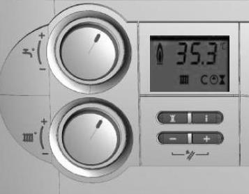
Fig. 3. Boiler display Vaillant Turbotec / Atmotec Plus The symbols on the display indicate the operating status. Wide service buttons with Click function. Functional diagram of the boiler Vaillant Atmotec plus / pro Vaillant boilers of the Atmotec series are devices operating on a flow-through principle for heating and heating hot water. These incinerators use the air of the room in which they are installed, therefore supply ventilation must always be provided for the proper functioning of the appliance. Exhaust gases are led out through the chimney under natural draft. The new flue gas sensors detect, in addition to the flue gas escaping into the room, the return flow of gases!
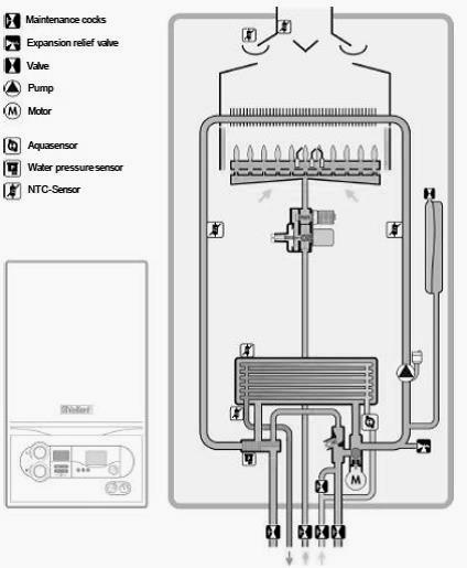
Fig. 4. Functional diagram of the Vaillant Atmotec plus boiler Draft stabilizer and flue gas sensors Air flow control is a safety unit that separates combustion processes from external influences. Boilers with an atmospheric combustion chamber in apartments can only be installed in cases where it is precisely known that carbon monoxide gases cannot accumulate in a dangerous concentration. Therefore, Vaillant Atmotec boilers, like all open chamber boilers, are equipped with flue gas sensors, which switch off the appliance after about 2 minutes when flue gases appear. Flue gas sensor, AtmoGuard system The Vaillant Atmotec plus wall-hung gas boiler is equipped with an AtmoGuard sensor. Unlike earlier solutions, AtmoGuard distinguishes not only the accumulation of gases, but also their reverse flow. Improved sensitivity is achieved by a new positioning of the sensor on the flue gas side. Now it is located on the side at the upper outlet of the traction stabilizer, and the second is inside and controls the gas flow. When flue gases escape into the room, hot flue gases flow past this temperature sensor; an increase in its temperature is detected, which leads to an automatic shutdown of the burner. The device is automatically switched on again approximately 15 B 20 minutes after switching off. If the switch-off is repeated twice during the interrupted heat consumption, the device is blocked permanently. The display shows the error message "F.36". Unlocking and restarting follows after pressing the reset button. If the device has been turned off three times in succession, then it is prohibited to turn it on without further monitoring of the gas path. Functional check of flue gas sensors - block the flue gas path with a Vaillant fan. - start the device. The device should turn off automatically within 2 minutes. The device is automatically switched on again approximately 15 B 20 minutes after switching off. The burner is blocked the whole time. By pressing the reset button, the device can be restarted again. Functional diagram of the boiler Vilant turbo tech Gas boilers Vaillant Turbotec series are independent of the room air and are used for heating and hot water production on a flow-through basis. These combustion devices draw in fresh air through the chimney systems, and the flue gases are discharged outside by a built-in fan. All appliances are certified with original Vaillant flue gas evacuation and combustion air systems only.
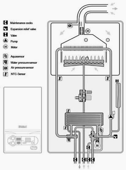
Fig. 5. Functional diagram of Vaillant Turbotec boilers Exhaust manifold - functional diagram The accumulator catches the flue gases appearing in the combustion chamber during fuel combustion and removes them from the device with a fan through the chimney.
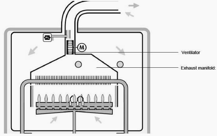
Fig. 6. Exhaust manifold - block diagram: Fan, exhaust manifold Fan / Air pressure sensor / Pitot tube The air pressure sensor (pressure switch) and the Pitot tube monitor the flow of gas-air masses. The pitot tube is located at the outlet of the fan, along the path of the flue gases. The pitot tube forms a pressure difference depending on the flowing air flow. A differential pressure appears between the outlet of the pitot tube (vacuum) and the low pressure chamber. Differential pressure only occurs when the combustion air intake is sufficiently dense and closes the microswitch of the air pressure sensor. This information goes on to electronics. The switch-on pressure of the pressure switch is between 80 Pa and 68 Pa. During servicing, the pitot tube should be checked for contamination that could significantly impair its function (e.g. insects) Flue gas diaphragms During the operation of the apparatus, the fan must be created with a pressure to overcome the resistance arising from the movement of gases along the entire path (combustion chamber, air inlet, outlet of combustion products). The maximum possible length of the flue gas and air removal systems is determined by the fan power and the cross-section of the flue systems. Adjustment of the air volume to different lengths and cross-sections of pipes is carried out with the help of exhaust gas diaphragms. The pressure transmission solution is new, since in previous models, there was a danger of water entering the pressure switch through the connecting hoses. In the new generation of boilers, a more reliable system (differential pressure: Venturi - UDK) should reduce the occurrence of faults, resulting in a weaker pressure signal than before. To increase the low pressure signal, Vaillant Turbotec boilers are supplied with new, pre-assembled flue gas diaphragms. These diaphragms are made of a special plastic reinforced with fiberglass. They amplify the pressure signal of the pitot tube. As a result, there is no need for one of the two tubes to the presostat. The built-in blower from the hose has further reduced the sensitivity to condensation. Wiring of boilers Vilant turbo tek / atmo tek The nominal voltage in the network must be 220 V; at voltages above 253 V and below 190 V, functional disturbances may appear. The Vaillant Turbotec / Atmotec boiler is equipped with a cable with a plug with a protective corner contact. The cable is connected to the device at the factory. The socket must be accessible to the user to be able to disconnect the plug at any time. The socket must not be located in protection zone I or II. Connecting regulators, accessories and external system components
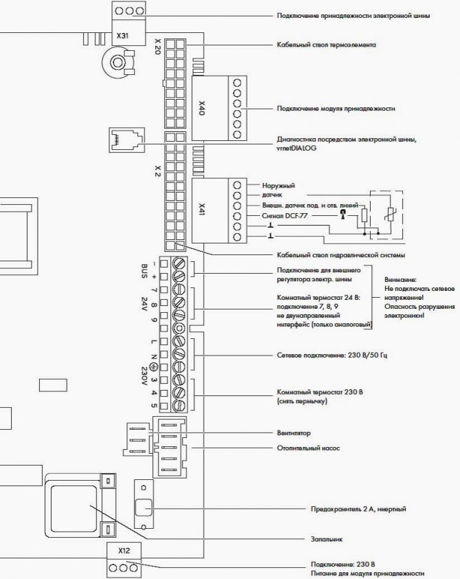
Fig. 7. Diagram of connections of boilers Vilant turbo tech
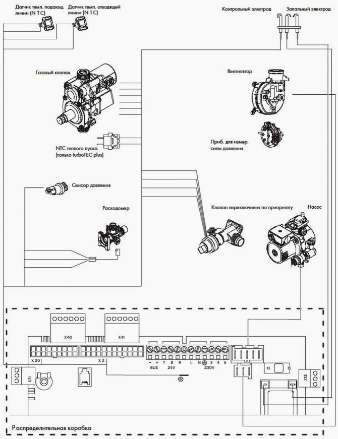
Fig. 8. Vaillant Turbotec pro / plus boiler wiring diagram
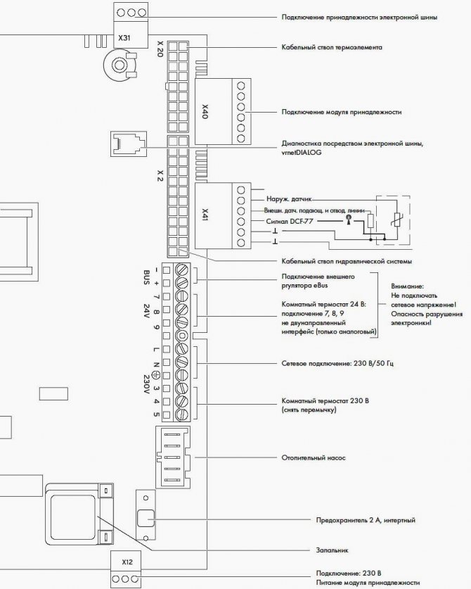
Fig. 9. Diagram of connections of boilers Vilant atmo tek
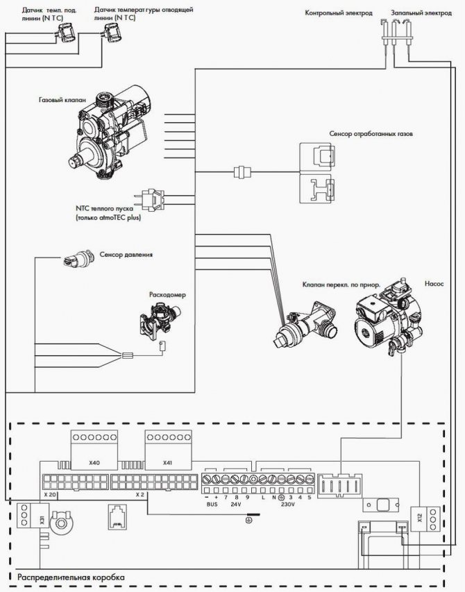
Fig. 10. Vaillant Atmotec pro / plus boiler wiring diagram Functional principle of the PTC flue gas sensors Since the boilers operate between full load (100%) and ignition mode (40%), the flue gas temperature can vary. Therefore, two sensors are installed in Vaillant Atmotec boilers. One of them is located directly in the flue gas stream in order to measure the actual temperature of the flue gases, and the second sensor is located on the outside of the draft stabilizer, from where flue gases can enter the room. If the temperature difference between the internal and external sensors is large enough, then the device works in normal mode.If the combustion products escape into the room, the temperature difference becomes smaller, and the electronics of the device recognizes this phenomenon as the release of combustion products into the room. If combustion products enter the room within 115 seconds, the device is turned off for 20 minutes. After the third 20B minute switch-off, the electronics checks the flue gas conditions again. If this time, too, the release of combustion products into the room is noted, the device is turned off and blocked. Within a 20B minute time delay when polling the status, the status message "S.52" appears. After the third attempt with the release of combustion products, the display shows the error message "F.36".
___________________________________________________________________________
___________________________________________________________________________
- Malfunctions of the AOGV-23 ZhMZ boiler
- Parameters and device of gas boilers AOGV and AKGV
- Boiler automation Baxi Luna-3 Comfort
- Installation and assembly of the Baksi Slim boiler
- Adjustments and maintenance of the boiler Beretta Chao
- Determination of error codes and malfunctions of Rinnai boilers
- Errors and malfunctions of the gas boiler Termet
- The meaning of the error code and malfunctions of Vilant boilers
- Determination of faults and errors of Wisman boilers
- Questions about the maintenance of boilers Navien
- Questions on malfunctions of Kiturami diesel boilers
- Junkers boilers - Masters answer user questions
- Experts answer questions about Electrolux boilers
- Expert answers for the repair of Nova boilers
- Questions about the service of Hermann boilers
- Answers from Daewoo boiler maintenance masters
- Questions about the maintenance of boilers Ferroli
- User questions on the repair of electric boilers Evan
- Because of what the gas boiler AKGV lights up and immediately goes out
- What is the malfunction of the Alpha Color boiler, if it shows the error code E01
- Because of what the AOGV boiler ignites and quickly goes out
- How to eliminate error E01 on the Baltgaz boiler
- What is the breakdown if Dani's boiler ignites, but immediately goes out
- Why does the Danko boiler light up, but quickly goes out?
- The Demrad boiler stopped holding pressure, what is the problem
- Because of what the Gazlux boiler began to warm up and make noise
- What is the reason if the Keber gas boiler lights up, but quickly goes out
- How to fix error code 01 on the Kiturami boiler
- Because of what the Conord boiler ignites, but immediately goes out
- What is the reason if the Lemax boiler ignites and quickly goes out
- Why does the Mimax boiler ignite, but it goes out sharply?
- Why the boiler The hearth ignites, but immediately goes out
- Why the Ross gas boiler lights up, but goes out quickly
- What is the malfunction if the Siberia boiler lights up and goes out sharply
- Why does the boiler Signal light up and go out sharply?
- Because of what the Termet boiler can make noise and heat
- Why does the gas boiler Thermotechnician ignite, but suddenly goes out?
- How can I fix the E01 error on the Thermon boiler
- For this reason, the Electrolux double-circuit boiler began to hum and heat up
- For what reasons the Ferroli gas boiler gives an error with the A01 code
- For some reason, the Immergaz boiler does not function on hot water supply
- Why does the Navien gas boiler constantly turn off and turn on immediately when heated
___________________________________________________________________________
___________________________________________________________________________
___________________________________________________________________________
- Heating boilers piping
- STS boilers
- Solid fuel boilers KBT
- Pellet boiler Peresvet
- Steel floor boiler Raton
- Solid fuel boiler Thermology
- Errors and malfunctions of the gas boiler Termet
- Repair of Thermon boilers
- Repair of boilers Nova
- Boiler service Hermann
- Comparison of gas boilers Lemax Premium-20 and Danko-20s
___________________________________________________________________________
- Maintenance of Daewoo boilers
- Boiler malfunctions Demrad
- Mora boiler malfunctions
- Boiler repair Westen
- Immergaz boilers malfunctions
- Types of solid fuel boilers
- Combined boiler models and designs
- Oil and double-circuit boilers
- Cast iron boilers for coal
- Boilers with simulating burners
- Imported boilers for heating systems
Features of use
Modern Valliant boilers are high-tech devices equipped with automation, which guarantees the autonomous operation of the equipment. By purchasing a device of this brand, the owner receives a unit that has everything necessary for simple and safe use.
Many of the models are equipped with a gas leakage warning system and a self-diagnosis system. But first of all, these "helpers" are designed to detect and eliminate the problem. At the same time, no one canceled the rules for the operation of boilers manufactured by the Vilant company.
In addition, routine inspections and maintenance must be carried out once a year. This significantly extends the life of any equipment, and boilers of this brand are no exception to the rule.
Another important factor that is relevant for the Vilant boiler is the correct installation. It must be carried out in accordance with existing standards and requirements, so this important matter should be entrusted to specialists. They have the appropriate skills, experience and license to perform such work.
The operation of any gas boiler largely depends on what type of equipment is installed. In any case, the instructions for the equipment contain a diagram of its installation, as well as the basic rules of use. For example, when buying a device with an open combustion chamber, you should constantly ventilate the room. Indeed, for their work, such boilers use oxygen circulating inside the house or apartment. Otherwise, the residents will have nothing to breathe, and the boiler will not work at full capacity.
Before using the boiler, you must carefully study the instructions and make sure that the heating system contains the right amount of liquid, as well as check the safety valve and the combustion field. If necessary, recharge the system with water or other heat carrier. This is done by adding fluid to the expansion tank or through an appropriate hole specially designed for this purpose. By the way, this should be indicated in the attached instructions.
Another important factor is boiler overheating, which is a rather unpleasant incident. The latest generation models have a special system that protects against such troubles. But if there is no such protection, then the air entering it should be removed from the system using a special valve.
Decoding the error
Code f28 appears on the display after several unsuccessful ignition attempts. The reasons can be divided into four groups:
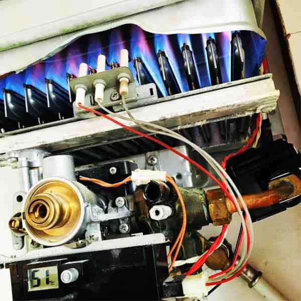
Successful attempt to ignite the vaillant boiler
- Blue fuel does not reach Vilant;
- the pressure in the pipe is below a critical value, the gas valve of the boiler does not work, and the electronics gives an error f28;
- problems with the supply voltage or grounding elements;
- malfunctions in the Vaillant boiler.
Understanding this and knowing the features of the gas supply to the facility, it is easy to develop an action plan for troubleshooting. In order to reduce the time spent on fixing the f28 error, Vilant should start with testing the most problematic sections of the circuit.
Video on how the F28 error code is displayed on the Vilant boiler.
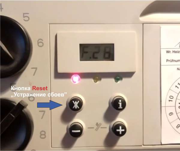
"Troubleshoot" button for clearing certain faults. Click it.
The first steps
- Reset. On the panel of Vaillant gas boilers there is a corresponding button (crossed out flame tongue symbol or REZET designation). If the f28 error is caused by an electrical failure, the problem is leveled.
- Check power supply. It is enough to turn on the lighting in order to understand by the light bulbs in the house, the voltage is normal or "subsided". In the absence of a stabilizer for the Vilant boiler at facilities in areas of mass development, this is one of the probable reasons for the appearance of error f28.
- Make sure the grounding is secure. Loose contact or broken wire: it won't take much time to check and fix the defect.
On a note!
The recommendation to "turn the plug" and re-insert it into the outlet in order to eliminate the error is not suitable for Vaillant boilers - the experiment will lead to the shutdown of the circuit breaker or the burnout of the electronic board.