- 1 Design of baking ovens
- 2 Types of devices for baking bread
- 3 DIY bread maker
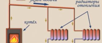
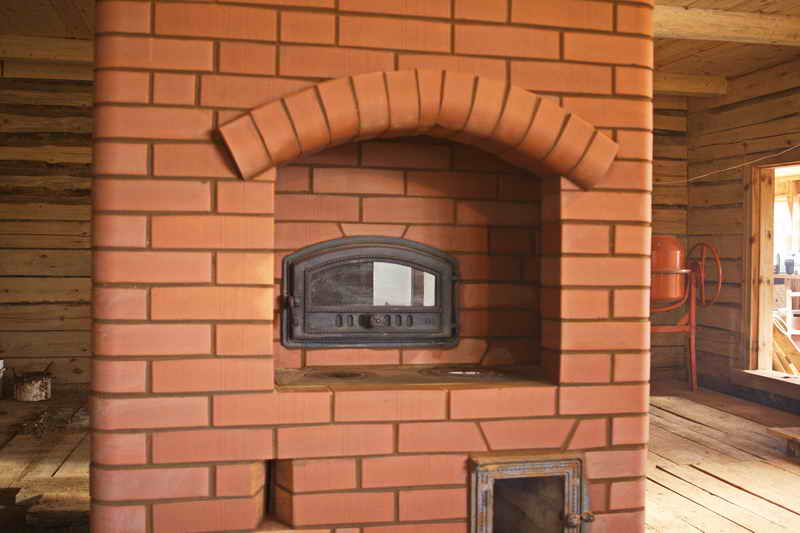
The stove has long been considered a multifunctional device. In almost every country house or dacha, you can see a stove device. With the help of a stove, a home is heated, they cook food on itbaking baked goods. Today, progress has reached the point that you can have your own bakery at home. Let's take a closer look at the features of all devices, which are used for baking bread, and also we will study the construction of a fireplace-oven with a bakery with our own hands.
Requirements for ovens for baking bread
Basic requirements for devices intended for baking:
- fire resistance;
- tightness;
- thermal insulation;
- mechanical strength;
- profitability;
- hygiene;
- cooking speed products;
- ergonomics;
- aesthetics.
Materials for the construction of a fireplace stove with a baking chamber:
- 1 - Kiln brick - about 1100 pcs. If you use fireclay bricks, then it will take about 150 units. (The number of bricks is given without taking into account the costs of the foundation and chimney).
- 2 - Knitting wire
- 3 - Doors-cleaning - 3 pieces
- 4 - Blower furnace with air regulation
- 5 - Fireplace door for the firebox 500x500 mm
- 6 - Basalt cord - 2 sets
- 7 - Pipe gate valve into brick - 3 pieces
- 8 - Grate with a working area of one or two bricks
Types of ovens for baking. Why is wood burning preferred?
The range of devices is quite wide:
- Deck bakery. It is used to make ordinary bread and other baked goods, most often from rye and wheat flour. Its structure consists of several tiers to which heat is supplied.
- Hearth. It is used for the preparation of pastry and yeast dough products. It is most often found in restaurants or in manufacturing. The design feature is the presence of hearths on which the workpieces move, which ensures uniform baking.
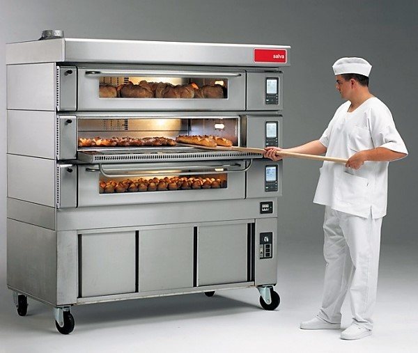
Photo 1. Hearth modular bread oven of the E series from the manufacturer Salva. Equipped with three cameras.
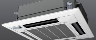
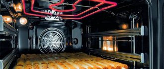
- Convection. It cooks not only traditional bread products, but also fish and meat. The device works on the principle of convection. It is used for both industrial and household purposes. Quite easy to operate.
- Tunnel. They are widely used in large continuous production. Cookies, buns, bread. Equipped with self-cleaning and oil supply systems.
- Electric bakery oven. It is the most cost-effective and economical. Designed for baking a huge range of products and cooking fish and meat dishes. Automatically maintains the optimal baking temperature.
- Rotary. Designed exclusively for confectionery. The main types of dough for such constructions are yeast, frozen and butter. The principle of operation is based on rotary circulation of hot air.
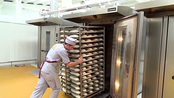
Photo 2. The process of loading a batch of bread into a large rotary oven from the manufacturer ENKOMAK.
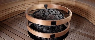
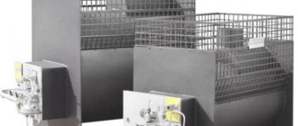
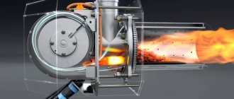
- Wood burning. Products in it are impregnated with the aroma of firewood, which increases the cost of finished products. The most economical, withstands the highest temperatures. It is considered environmentally friendly. It runs on wood and has many advantages.
Benefits wood-fired ovens:
- giving natural aroma smoke to the finished product;
- preservation of performance in the field in the absence of electricity;
- energetic competitiveness.
At home, ordinary electrical devices or wood-burning ones are most often used.
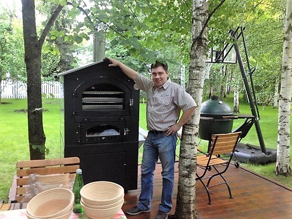
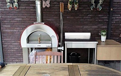
Photo 3. A wood-burning oven for baking bread can be installed in the yard, it is more mobile than an electric one.
Choice of the furnace door and the door of the baking chamber.
Usually, when I meet with a customer for laying a fireplace stove, one of the main questions I ask him is what size of the furnace door do you want to see, what size the hearth of the breadmaker should be, i.e. whether he is going to cook food directly on the hearth, in a frying pan, barbecue grill or on a baking sheet, as well as how much of the house should the stove heat. The main element of the furnace on which most of the dimensions depend is the furnace door, the larger it is, the larger the section of the chimney should be, the volume and height of the smoke collector on the firebox from here and the height of the entire furnace. If you decide to make a stove with the largest possible door, such as the LK 300 with landing dimensions of 500x500mm and external dimensions of 600x600 mm and a weight of 25 kg, be prepared to treat the masonry with maximum responsibility, insufficiently squeezed chimney channels or pipes, narrowing of summer smoke channels when passing through a bread maker and the connection of a chimney sandwich to a brick pipe all this can cause puffing of the stove when the firebox is open with the door open in fireplace mode. Also, do not forget that the volume of the smoke box above the firebox must be at least 2/3 of the volume of the firebox itself and the pipe section must be at least 250x120 mm with its length from the colossus at least 5 meters, which corresponds Swedish pipe calculation formula for open fireplaces. If you do not have much experience in laying brick ovens, I recommend choosing a smaller furnace door, for example DE-424-1A (external size 424 (w) x395 (h) mm, internal size 370x341) or DV544-2A (490x291 mm). For the door of the baking chamber, the size is less important, since in a fully open mode it does not heat up (it is completely closed during flow heating from the firebox, and the slack is slightly open by 10-20 mm during hearth heating), while this door, unlike the furnace, must be sealed, for example LK 322 or LK 324. Regarding the presence or absence of glass in these doors, this is a purely customer's choice, but I can say that if you do not constantly clean the doors from soot, it will be quite difficult to achieve full transparency of the glasses, i.e. speaking in simple terms, the glass will smoke a little.
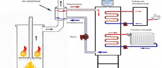
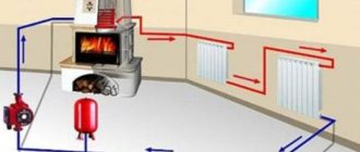
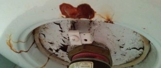
Wood-burning stove device
The wood-burning stove must have chimney, which will ensure the removal of gases. Her power depends on size and power consumption. The fire affects the coating of the device itself, which gives off heat to the food.
Important! It is convenient not only for creating baked goods, but also for heating premises.
The main elements of the device:
- heating element;
- window;
- belt or conveyor for products;
- steam humidifier;
- chimney.
Fuel
Mainly woodpressed pallets, fuel briquettes or peat... The advantage of firewood is its long-term preservation of heat, long-term support of the combustion process and environmental friendliness.
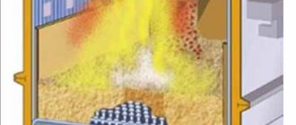
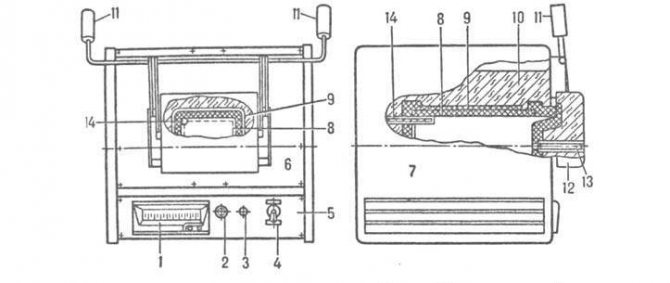
Standard diagram of an electric muffle furnace
As you can see in the photo below, the electric muffle furnace circuit provides for both the injection of high temperatures and their maintenance. For the safe operation of the heating device, excess moisture and steam are removed. Insulation of working elements is also performed. Equipment consists of:
- Regulating millivoltmeter (No. 1).
- Indicators (No. 2).
- Fuse (no. 3).
- Switch (No. 4).
- Control block (No. 5).
- Heating box (no. 6).
- Buildings (no. 7).
- Ceramic muffle (No. 8).
- Heating element (no. 9).
- Thermal insulation layer (No. 10).
- Counterweight (no. 11).
- Doors (no. 12).
- Control thermocouple compartment (# 13).
- Opening for the thermostat (no. 14).
Detailed diagram of an electric furnace with a rectangular muffle
Basic recommendations for choosing
When choosing a wood stove, you need to understand purposes of exploitationand appliance: industrial or home.
Go for a leaner and more compact version if you're cooking for the family... It is unlikely that you need the amount of products that, for example, a tunnel oven produces.
Pay attention to kitchen area... Some devices take up a lot of space due to their size and the possibility of connecting a chimney.
Depending on the type of oven, it can cook not only bread, pizza, pies and pastries, but also first, second courses, fish or meat.
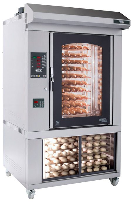
Types of bread makers
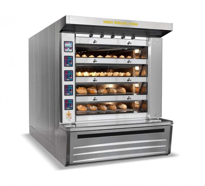
Photo of a baking oven
Bakery ovens are divided into a fairly large number of models, each of which has its own characteristics.
In this case, the main classification of baking ovens is carried out according to several criteria.
- Furnace heating system. Depending on the type of working surface heating system used, baking ovens are:
- With direct recoil on the surface. These are wood-burning stoves;
- Devices that do not have a direct kickback on the heating surface of the furnace. This category includes thermal oil oven models.
- The principle of heat transfer in the oven. To create baked goods, a different principle of heat delivery to work surfaces can be used:
- Through radiation and heating tubes;
- Through fuel gases or hot air that circulates inside the oven. These are convection ovens.
- Furnace channel designs. Bread makers are also classified according to the type of channels. They can be:
- With high thermal resistance. These bread ovens have brick or ceramic walls. During their construction, a certain order is observed;
- With little resistance. This category includes furnaces whose walls are made of steel sheets. This feature differs in the basic electric bread maker.
- The fuel used for the bread machine. The widest range of baking oven options is presented here, as the fuel for creating baked goods can be used in different ways:

Photo of a baking oven
- Liquid fuel;
- Gas;
- Electricity;
- Firewood;
- Coal, etc.
- Method of loading baked goods. All ovens are equipped with a chamber for placing baked goods inside it. At the same time, the loading into the chambers of the oven for making bread is different:
- Floor stove. This oven has several floors, on each of which there is a tray with blanks for bread and pastries. Storey ones can have stationary or sliding pallets. The latter option is more convenient if the unloading of the finished bread is done by hand;
- Tunnel stove. These are long enough chambers for baking, through which the workpieces pass. Designed for a large amount of loaded bread, which allows for quick preparation of impressive portions of baked goods. Loading methods like this are relevant for large bakeries;
- Rotary ovens. Based on the rotation of pallets with baked goods. The rotary ovens have a large usable area, which allows you to cook large quantities of bread at the same time.
Requirements for bread makers
A bakery oven must meet certain requirements in order to meet the needs of the manufacturer.
- Stove capacity. If this is an oven for a bakery that provides baked goods to an entire district or city, the equipment must provide the ability to simultaneously load a large number of bread blanks. The Russian traditional oven allows you to bake several loaves at a time, which is quite enough for home consumption.
- Camera height. An electric, gas or wood-fired stove must be equipped with sufficiently high chambers. This is due to the fact that most types of bread begin to grow when baked.If the chamber is low, the bread will simply bump into the ceiling, burn, or take on an irregular shape.
- Autonomous heating elements for stoves. Moreover, for better baking with your own hands, it is better to equip the oven with two independent heating elements - above and below. So the baking will take place evenly, and the user will be able to control the degree of roasting of the products.
- Steam generation function. When baking at home with your own hands, for which a Russian oven or an ordinary oven is often used, the issue of steam generation does not play a big role. But in production workshops, the absence of such a function leads to the fact that the upper crust dries up, becomes covered with cracks, and burns out. From this, the presentation is lost, baked goods can be rejected, and therefore the manufacturer will lose money. To prevent this, it is necessary to purchase bread makers with a steam function.
- Heating temperature - at least 300 degrees. Modern household ovens are equipped with thermostats that allow you to cook food at different temperature conditions. The requirements for bread makers are slightly higher. Most of the baked goods are cooked at temperatures from 300 degrees Celsius. But for certain recipes and types of bread, a temperature of 400-500 degrees may be required. Not all bread makers are capable of providing such heating, but without it, baking simply will not work. Therefore, when buying equipment, check what temperature range it has and whether it will be able to implement the recipes that you plan to use in the production of baked goods.
[1] Convection - the phenomenon of heat transfer in liquids or gases by flows of matter. It arises under the influence of gravity due to the difference in the density of matter in areas with different temperatures.
Heating the elements
Spiral or zigzag heating elements are made of wire, and zigzag heating elements are made of tape (Fig. 1-5). Zigzag heating elements with a large cross-section and mechanical strength are installed on the walls and vault using special fasteners made of heat-resistant materials, the bottom heating elements are laid directly on the hearth stone or bricks. Also, heating elements are made on ceramic frames of various shapes (2) or fit into the grooves of the lining (3). In furnaces with electric heaters and salt baths with an operating temperature of up to 600C, tubular heating elements - heating elements are used (Fig. 1-6). The tubular heating element consists of a nichrome spiral (2), which is located in a tube made of heat-resistant alloy (1). In the space between the inner wall of the tube and the coil is crushed crystalline magnesium oxide (periclase), or powdered quartz (3), which have poor electrical and good thermal conductivity. The tubular heating element is equipped with leads (5) and insulators (4). In furnaces with operating temperatures above 1100 - 1150C, non-metallic heating elements are used, which are made, for example, of silicon carbide (carborundum). Graphite, carbon, molybdenum and tungsten heating elements are also used. The use of molybdenum and tungsten heating elements is only possible in a protective atmosphere.
Approximate power consumption of electric furnaces:
- from 8 to 160 kW chamber furnaces;
- from 25 to 160 kW shaft furnaces;
- from 20 to 1000 kW chamber furnaces for drying electrical products;
- from 10 to 150 kW drum furnaces;
- from 90 to 270 kW pusher furnaces;
- from 750 to 1100 kW pusher furnaces with cooling chambers;
- from 6 to 800 kW conveyor furnaces;
- up to 1400 kW conveyor furnaces with cooling chambers.
Simplified electrical diagram of the resistance furnace (Fig. 1-11):
List of elements of the electrical circuit of the resistance furnace:
F1 - automatic circuit breaker for furnace heating elements KM1 - contactor for furnace heating elements T - furnace autotransformer B - temperature sensor F2 - automatic switch for the electric drive of the furnace door KM2 - contactor for the electric drive of the furnace door (opening) KM3 - contactor for the electric drive of the furnace door (closing) Y - electromagnetic brake F3 - furnace control circuit breaker S1 - stove door electric drive button (stop) S2 - stove door electric drive button (opening) S3 - stove door electric drive button (closing) S4 - stove door limit switch (triggered when the door is fully opened) S5 - final oven door switch (triggered when the door is fully closed) M - oven door drive motor TRS - temperature control device S6 - operating mode switch (automatic-off-manual) KA - heating element contactor relay H1 - signal lamp (temperature exceeded, or n controlled temperature rise) H2 - signal lamp (heating elements on) H3 - signal lamp (heating elements off) R1, R2, R3 - additional resistors of signal lamps
Electric diagram of arc furnaces, equipment elements
Figure 1.7 shows the power supply diagram of an electric arc furnace.
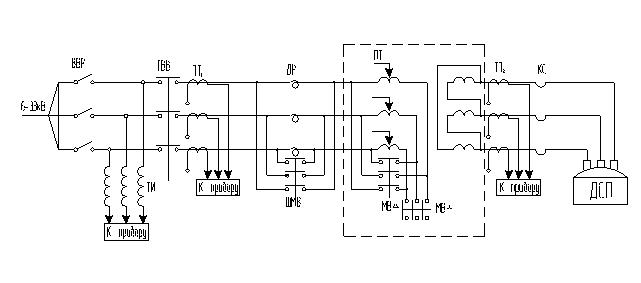
Chipboard power supply diagram
PT - furnace transformer; VVR - high-voltage disconnector; GVV - main high-voltage switch; ТН - voltage transformer; TT1 and TT2 - current transformers; ShMV - shunt oil switch; MVΔ, MV - oil circuit breakers; KS is a short network.
High-voltage disconnector (VVR) - serves to disconnect the electric furnace from the high voltage buses for the period of repair of the furnace, mechanical and electrical equipment.
The voltage from the high-voltage switchgear through the line (power supply circuit) is supplied to the furnace substation, which houses the furnace step-down transformer and auxiliary electrical equipment.
The electric furnace switching circuit provides:
- metering of active and reactive electricity from the high side of the furnace transformer;
- active power measurement;
- voltage measurement on the high and low side of the furnace transformer;
d) signaling the position of the high-voltage switch and warning signaling about the temperature rise of the furnace transformer oil and the activation of the gas relay. DC power supply of signaling circuits and control is carried out from a power supply unit of the BPN-1002 type, installed separately.
The current reduced to 407 V is supplied directly to the electric furnace. The current strength in this section of the electric furnace is up to 28.4 kA, as a result of which significant power losses take place in the section from the furnace transformer to the electrodes. To reduce these losses, the furnace substation is brought as close as possible to the furnace, and the section of the circuit from the transformer to the electrodes is made as short as possible (short network).
Thus, the EAF electrical circuit includes the following equipment:
- step-down transformers with built-in chokes, which serve to increase the inductive resistance of the network and improve the arcing conditions.
- a short network connecting the secondary terminals of the transformer with the furnace electrodes.
- switching, measuring and protective equipment, high and low voltage wires.
Furnace transformer. Serves for converting high voltage electricity into low voltage energy. Step-down furnace transformers, due to special operating conditions, are characterized by a number of features:
- high rated current on the low voltage side;
- increased inductive resistance of the windings, necessary to limit the strength of short-circuit currents no more than 3.5 A / mm2 multiples in relation to the nominal current strength, since steel-making furnaces operate with frequent short-circuit of electrodes to the charge when the arc is ignited and the charge collapses during the melting period;
- increased mechanical strength of fastening of windings and branches, designed for frequent surges of currents and short circuits;
- the ability to regulate the voltage under load over a wide range.
The transformer consists of three high-voltage windings made of copper wire of relatively small cross-section and three low-voltage windings made of large-cross-section busbars.
The primary winding has a number of taps of different numbers of turns, which allows you to change the ratio of the number of turns of the primary and secondary windings and the value of the secondary voltage. All six windings are mounted on three interconnected cores (magnetic circuits). The transformer magnetic core (transformer skeleton) is charged from cold-rolled steel plates with a thickness of 0.35 mm. The transformer winding is concentric. The first on the rod is the LV winding, made of a two-way screw made of copper conductors with paper insulation. The HV winding taps from the reactor are made of a flexible copper cable. To prevent kinks and breaks at the point of connection to the switch, the bends are terminated with flexible connections (dampers).
The transformer core with windings is placed in a tightly closed casing filled with transformer oil. The oil is a good electrical insulator and has great thermal conductivity, which allows heat to be removed from the coils and core of the transformer. The transformer heats up due to power losses due to the active resistance of the copper windings and to the magnetization reversal of the core.
Above the transformer there is an expansion tank connected to it, which contains a reserve of oil. This ensures that the entire volume of the transformer is constantly filled with oil and the contact surface of the oil with air is reduced. In case of damage or exposure of the windings, the oil decomposes with the release of gas. The appearance of gases in the transformer is signaled by a gas relay installed in the upper part of the transformer tank. The gas relay gives a warning signal when a small amount of gases appears - oil decomposition products. To limit the strength of short-circuit currents, a choke is built into the transformer, which is switched on and off by a special bypass contactor.
A current transformer is installed to power the protection, control and measurement circuit, as well as the arc power regulator. The furnace transformer is also equipped with oil level and temperature control devices. To protect the working windings and the switching device from overvoltages induced from the side of the high voltage winding, valve arresters are installed on the transformer.
Device for switching voltage steps. Designed for a stepwise change in the power released in the arcs. Power regulation is carried out by switching the connection circuit of the primary windings of the transformer (from "star" to "delta" and vice versa).
The switching of the voltage steps of the transformer (PSN) is carried out remotely. PSN must be performed with the high-voltage switch off, for which the PSN control circuit provides for a blocking, which excludes the possibility of the switch operation when the switch is on.
PSN control can also be carried out manually using a handle located on the drive mechanism.
Throttle. Serves to limit operational short-circuit current surges and stabilize arc burning during the melting of the charge.During the rest of the melting periods, when the furnace is running on liquid metal, the electric mode is relatively quiet. The choke is bridged with an oil shunt switch. The value of the relative inductive resistance is 10%. So that the inductance of the choke does not drop with increasing current, the choke is made with low induction in the steel core and is built into the transformer. The choke winding, together with the core and the transformer winding, is immersed in oil.
Shunt oil switch. Disconnectors, a power switch and a high-voltage cable are applicable for the supply from the high-voltage switchgear to the furnace transformer. In addition to the disconnectors installed in the supply circuit, for safety reasons, the installation of earthing disconnectors is provided.
Power switch. In the power supply circuit of the electric furnace, two three-phase power switches are installed. One switch is located in the high voltage switchgear on the outgoing line supplying the furnace. It serves to turn off the furnace in emergency modes, i.e. in case of short circuits, when the current strength exceeds the permissible values, with overheating of the transformer, violent gas evolution in the transformer (turn circuit) and other such cases.
The second operating switch, located in the immediate vicinity of the furnace, serves for its remote shutdown when switching from the "triangle" to the "star" circuit, at the end of melting, removing slag, loading materials with a loading crane. While high reliability is required from the switch that turns off the furnace in emergency modes, high durability is required from the operating switch along with reliability.
Overcurrent protection is performed on three current relays and a time relay. With such a protection setting, in the event of operational short circuits (SC), after the current relays operate with a time delay of 7–8 seconds, a sound signal is given, then after 10 seconds the operating switch is turned off.
Emergency shutdowns of the circuit breaker, in addition to shutdown during long-term operational short circuits, also occur when the gas relay of the PT is triggered, when the furnace is tilted, when the PSN PT is operated and when the steelmaker's key is turned off, which allows the high-voltage switch to be turned on.
The switch in the complex distribution device allows frequent operations and serves both for operational switching on and off of the electric furnace, and for switching off the electric furnace during prolonged overloads of the furnace transformer by current and other emergency conditions of the installation. When a complex distribution device with an operating switch is located near the electric furnace, protection against emergency short-circuits on the high voltage side of the PT is provided by another switch located at the workshop substation on the feeder supplying the electric furnace. When the complex switchgear is located at the workshop substation, the operational switch simultaneously protects against emergency short-circuits on the high voltage side of the electric furnace feeder, provided that the complex switchgear is checked for dynamic, thermal stability and permissible shutdown power.
Grounding of the electric furnace. The earthing device is made as a common one for high and low voltage installations. Natural ground electrodes of metal structures and other structures that have a reliable connection to the ground, as well as cable sheaths and their zero conductors are used as grounding devices.
Air disconnectors. They serve to disconnect and ground an electric furnace, on the line of which repair work is to be carried out. Disconnection of disconnectors and earthing of the unit is carried out when the power switch is off.In the on and off positions, the knives are locked with a special hook, which excludes spontaneous opening or closing