Register Login
Date of publication: October 25, 2013
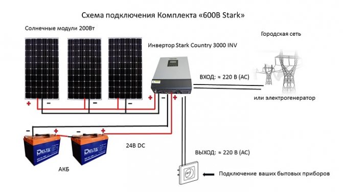
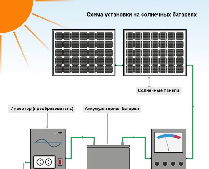
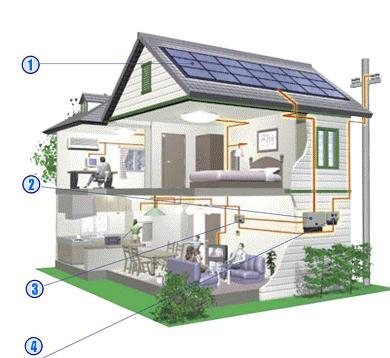
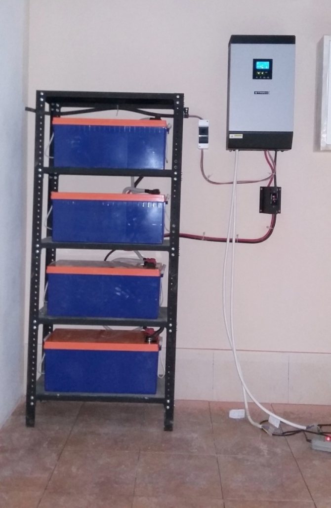
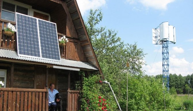
Any autonomous power supply system powered by solar energy includes several essential elements: solar panels or batteries, an inverter, a charge and discharge controller and, of course, a battery. This is what will be discussed in our today's article. As you know, solar panels are designed to generate energy from solar radiation, and so solar batteries perform a different function. Their primary task is the accumulation of electricity and its subsequent return.
The main technical characteristic of a battery is its capacity. By this indicator, you can determine the maximum operating time of the power supply system in autonomous mode. In addition to capacity, one should take into account the service life, the maximum number of charge-discharge cycles, the operating temperature range and other indicators. The average battery life is 5-10 years. This figure depends on the type of battery and the conditions of use.
What is a household solar panel
Solar energy is a real find for obtaining cheap electricity. However, even one solar battery is quite expensive, and in order to organize an effective system, a considerable number of them are needed. Therefore, many decide to assemble a solar panel with their own hands. To do this, you need to be able to solder a little, since all the elements of the system are assembled into tracks, and then attached to the base.
To understand whether a solar station is suitable for your needs, you need to understand what a household solar battery is. The device itself consists of:
- solar panels
- controller
- battery
- inverter
If the device is intended for home heating, the kit will also include:
- tank
- pump
- automation kit
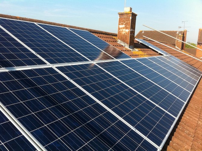
Solar panels are rectangles 1x2 m or 1.8x1.9 m. To provide electricity to a private house with 4 residents, 8 panels (1x2 m) or 5 panels (1.8x1.9 m) are needed. Install the modules on the roof from the sunny side. The angle of the roof is 45 ° with the horizon. There are rotating solar modules. The principle of operation of a solar panel with a rotating mechanism is similar to a stationary one, but the panels rotate after the sun thanks to photosensitive sensors. Their cost is higher, but the efficiency reaches 40%.
The construction of standard solar cells is as follows. The photovoltaic converter consists of 2 layers of n and p type. The n-layer is made on the basis of silicon and phosphorus, which leads to an excess of electrons. The p-layer is made of silicon and boron, resulting in an excess of positive charges ("holes"). The layers are placed between the electrodes in this order:
- anti-glare coating
- cathode (electrode with negative charge)
- n-layer
- thin separation layer that prevents free passage of charged particles between layers
- p-layer
- anode (electrode with a positive charge)
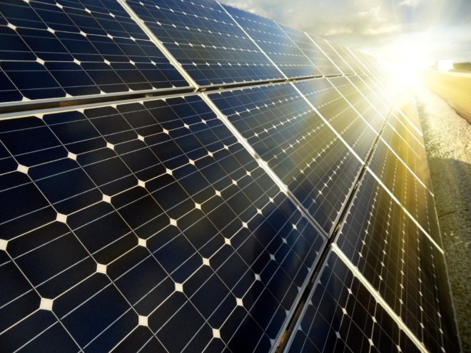
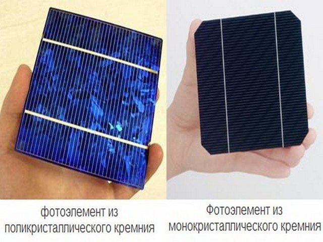
Photovoltaic modules are produced with polycrystalline and monocrystalline structures. The former are distinguished by their high efficiency and high cost. The latter are cheaper, but less effective. The capacity of the polycrystalline is sufficient for lighting / heating the house. Monocrystalline ones are used to generate small portions of electricity (as a backup energy source). There are flexible solar cells based on amorphous silicon. The technology is in the process of modernization, as The efficiency of an amorphous battery does not exceed 5%.
Three Phase Solar Inverter System
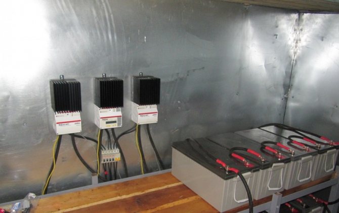
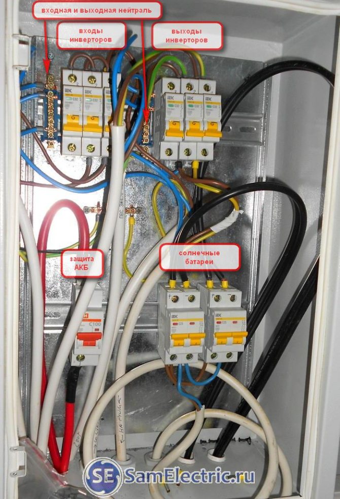
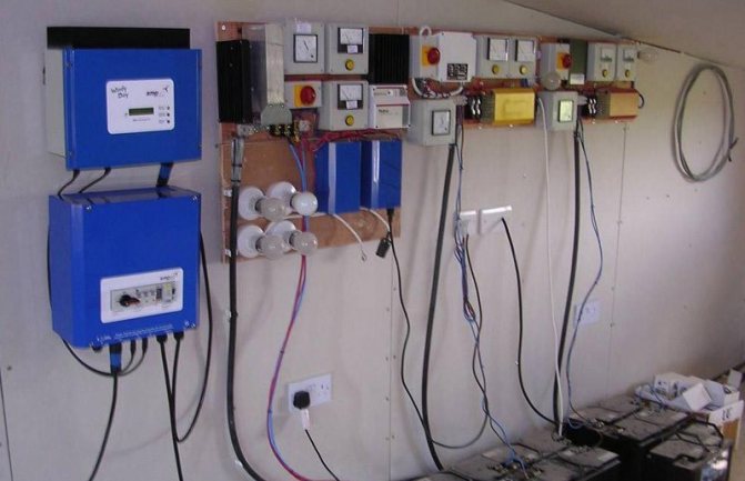
I will not bore the reader, I will give a few photos from the installation of solar inverters in a three-phase power system. The connection diagram is as follows:
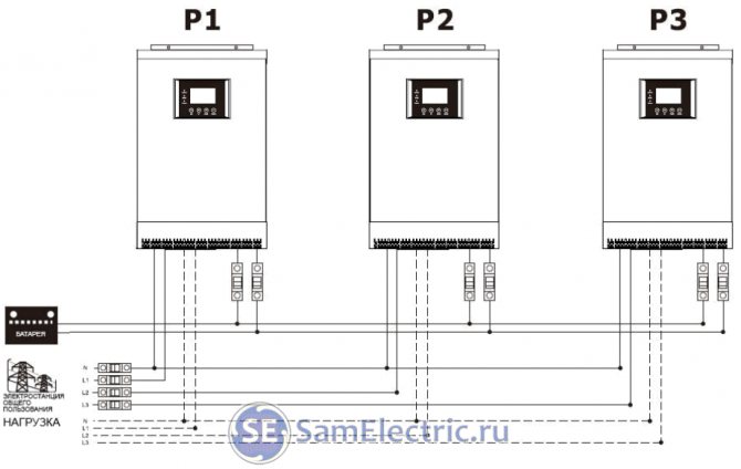
Three phases - connection diagram of solar inverters
In this scheme, three Ecovolt inverters are used, each for its own phase. For communication, they are equipped with parallel boards, which are connected via parallel cables:
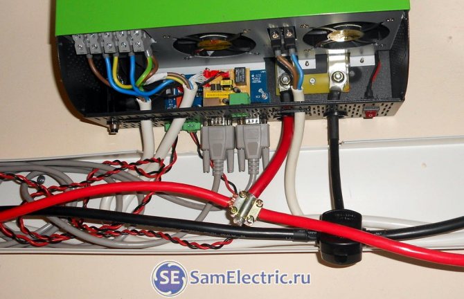
Three-phase power system for the home. Inverter connection. Working moment, installation process
For all connections, one more shield is needed, where all voltages come:
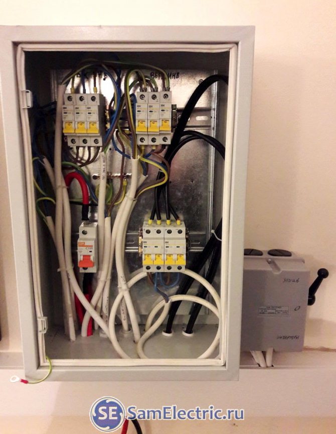
Electrical panel for connecting inverters
To increase the reliability of the system, a rocker switch is needed, since in case of an accident (and any electronic device has the right to breakdown)) even one of the inverters will turn off the entire system. And then you can apply voltage directly from the street.
This is similar to the simplest ATS, when the house can be powered from the city network or from a generator through such a switch. I wrote about this in detail in the article on the Huter generator.
Here's a closer look at the failover switch:
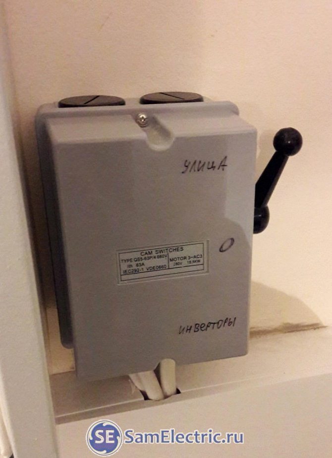
A switch for selecting power at home - through inverters or from the street, as before
And here is a closer look and with explanations of the internal diagram of the electrical panel for connecting the inverters:
Connecting solar inverters in a three-phase network
Solar panels in this configuration are connected to one of the inverters, which will be the main one. It will control the charge on solar batteries.
This is how the solar panels are fixed on the roof, there is only such a way to install solar panels for the house.
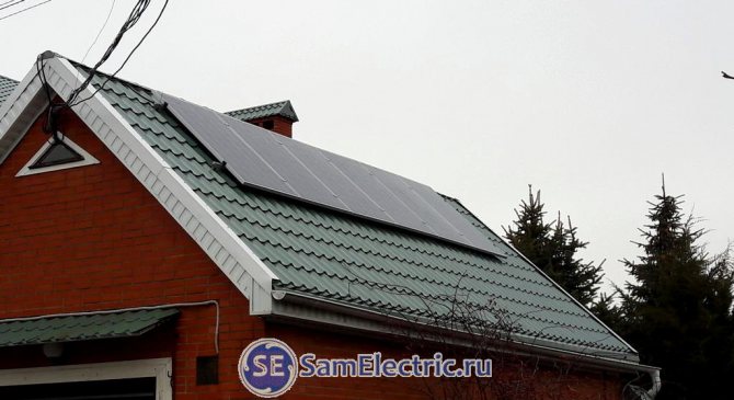
Mounting the solar array on the roof
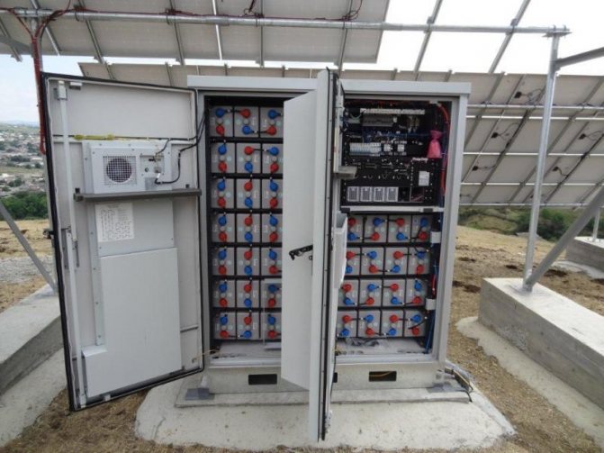
This is one half, the other is on the other slope. In total - 12 solar panels, each with 24 Volts, power 260 W. Each such half contains three batteries connected in series, these triplets are connected in parallel. As a result, in theory, all 12 batteries will give 3100 watts. But this is if the sun's rays fall perpendicularly on all the batteries, which cannot be the case.
As a result, the three-phase power system looks like this:
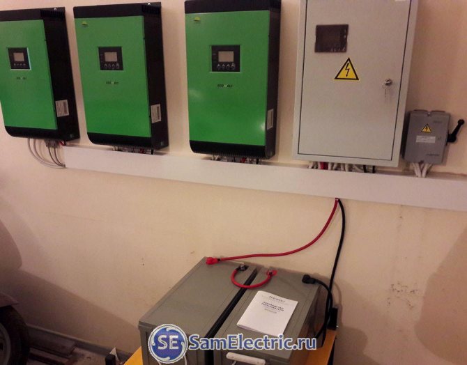
Three-phase solar inverter system for home power supply
Solar cell device
When planning to connect solar panels with your own hands, you need to have an idea of what elements the system consists of.
Solar panels consist of a set of photovoltaic batteries, the main purpose of which is to convert solar energy into electrical energy. The current strength of the system depends on the intensity of the light: the brighter the radiation, the more current is generated.
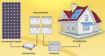
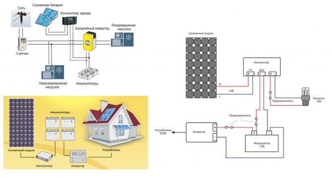
In addition to the solar module, the device of such a power plant includes photovoltaic converters - a controller and an inverter, as well as batteries connected to them.
The main structural elements of the system are:
- Solar Cell - Converts sunlight into electrical energy.
- A battery is a chemical current source that stores generated electricity.
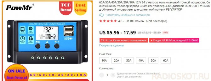
- Charge controller - monitors battery voltage.
- An inverter that converts the constant electric voltage of the battery into an alternating voltage of 220V, which is necessary for the functioning of the lighting system and the operation of household appliances.
- Fuses installed between all elements of the system and protecting the system from short circuits.
- A set of connectors standard MC4.
In addition to the main purpose of the controller - to monitor the voltage of the batteries, the device turns off certain elements as necessary. If the reading at the battery terminals during the daytime reaches 14 volts, which indicates that they are overcharging, the controller interrupts charging.
At night, when the battery voltage reaches an extremely low level of 11 Volts, the controller stops the operation of the power plant.
Add a link to the discussion of an article on the forum
RadioKot> Circuits> Power supply> Chargers>
| Article tags: | Add tag |
Solar battery charging
Author: SSMix Published 09/17/2013 Created with KotoRed.
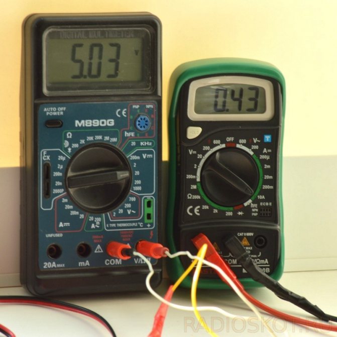
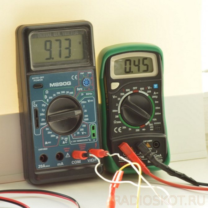
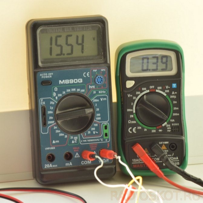
Somehow, for the standby recharging of 3-finger NiMH batteries, 3 solar batteries made of polycrystalline silicon of the type YH40 * 40-4A / B40-P dimensions 40 × 40 mm each. In the datasheet, they indicated the current Isc = 44 mA and the voltage Uхх = 2.4 V. It was also indicated that, unlike monocrystalline silicon, these elements slightly reduce the power in case of cloudiness or partial shading. By connecting three of these solar cells in series and applying three NiMH batteries to the series-connected three NiMH batteries through a Schottky diode, the simplest charger was obtained. The simplest, since with such a switching scheme, the batteries were charged only in bright sunlight. In cloudy weather and under artificial lighting, the output voltage of the solar cells dropped significantly, as a result of which there was not enough voltage for charging.
First, a 5V pulse boost converter on the NCP1450ASN50T1G with standard piping was simply added to the solar panel,
but the result was unsatisfactory.
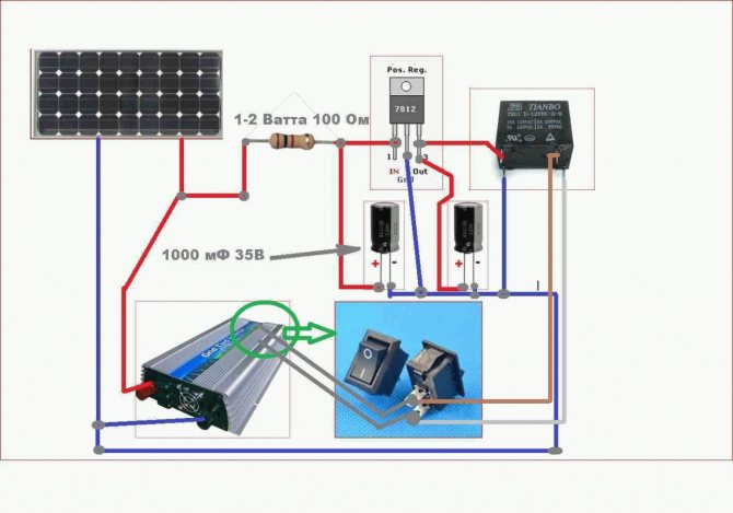
After starting the converter, the voltage at the output of the solar battery sagged significantly, and even in good sunlight did not exceed 2V. In this case, the charging current of the batteries was several times lower than when the solar battery was directly connected to them. Connecting the work enable pin 1 (CE) DA1 through a voltage divider to increase the converter start-up threshold also did not significantly improve the situation. It became clear that in low light, the operating mode of the circuit should be completely different. First, you need to accumulate the charge from the solar cells on an additional capacitor, and then upon reaching a certain threshold voltage on it, "throw out" this charge to the step-up converter. In bright light, when the voltage at the output of the solar battery is sufficient to directly charge the batteries, the boost converter should automatically shut down. As a result, the following scheme was developed, providing an automatic transition from one to another operating mode:
The device works as follows. At the initial turn on (lighting), all the transistors are closed and the capacitor C1, connected in parallel with the solar battery, is charged. The voltage from C1 through the choke L1 and the Schottky diode VD3 also goes to the power input of the DA1 NCP1450ASN50T1G boost converter microcircuit, to the capacitor C4 and to the positive terminal of the GB1 battery. The negative terminal of GB1 is connected to the common bus of the circuit through the VD4 diode to exclude the battery discharge current through the circuit in the absence of external lighting. Upon reaching the threshold voltage for opening VT3 (about 1.8V) on the capacitor C1, the latter also opens the transistor VT4. At the same time, an unlocking voltage (> 0.9V) is applied to the control input CE DA1 and a pulse boost converter (DA1, R10, C3, VT5, L1, VD3, C4) is started, recharging the capacitor C4. Simultaneously with the operation of the converter, the red LED HL2 starts to light up. If the illumination of the solar battery is insufficient to maintain the operating current of the load, the voltage on the capacitor C1 will decrease, VT3, VT4 will close, the control voltage at the CE DA1 pin will fall below 0.3 V and the converter will turn off, and the HL2 LED will turn off. Since the load for the solar battery has been disconnected, the process of charging the capacitor C1 to the opening threshold voltage VT3 will start again.The converter will start again and the next portion of the charge will enter the capacitor C4. After a series of such cycles, the voltage across C4 will increase to the opening voltage of VD4 plus the total voltage across the batteries. Battery charging current will flow through GB1, VD4. A current of several mA will be enough to drop the voltage across VD4, at which the transistor VT2 begins to open. The VD4 diode is used as a current sensor. The pulsating voltage from the solar battery and C1 is supplied to the rectifier VD1 (BAS70), C2, R1. From the resistor R1, the rectified voltage is supplied to the series-connected З-И VT1 and К-Э VT2. If the energy generated by the solar battery becomes enough for the simultaneous opening of VT1 (voltage on C2, R1) and VT2 (battery charging current), then the lower arm of the divider R4 will be bypassed, which will lead to an increase in the opening threshold of VT3, VT4 to start the boost converter. Thus, the more energy is generated by the solar battery, the higher the converter start-up threshold becomes, i.e. an increasing charge of energy is removed from the storage capacitor C1. With sufficient lighting, when the voltage of the solar battery under load is sufficient to directly charge three batteries (through L1, VD3, VD4), open VT1, VT2 shunt R4 so that the boost converter is in the off state. In this case, the red LED HL2 stops flashing. The green LED HL1 is constantly on when the voltage on C1 is more than 2V to indicate that the device is working. The process of automatic switching of the operating mode is smooth, adapting to the ambient light. In low light, the red LED flashes occasionally. With increasing illumination, the blinking frequency increases, and the green LED also starts blinking in antiphase. With a further increase in illumination, when there is no need for a step-up converter, only the green LED remains on. In clear sunny weather, the battery charging current reaches 25 mA. To limit the output voltage of the solar battery at 5.5 V, the Zener diode VD2 is intended, since according to the datasheet on the NCP1450A, the maximum input voltage for it should not exceed 6 V.
The device is assembled on a printed circuit board made of one-sided foil-clad fiberglass with dimensions 132x24mm.
All elements, except for the power connector for connecting batteries, are in SMD design. LEDs HL1, HL2 - ultra bright 1206 standard size. The type of LEDs purchased remained unknown, but they are quite bright, and begin to glow already at microampere currents. Resistors and ceramic capacitors - standard size 0805 (C3 and R10 - 0603, but you can also solder 0805 in two floors). Capacitors C1, C4 - tantalum, standard size C. Choke L1 - type CDRH6D28 15μH, 1.4A. Transistors are widely used, SOT-23-3 package. The power connector is standard. Attention! The board is wired for the external positive contact of the plug.
Device setup is practically not required. If necessary, by selecting the resistance of the resistors R2, R7, you can set the required brightness of the available LEDs. By selecting the resistor R4, you can achieve the most optimal operating mode of the converter (to the maximum efficiency) with a reduced illumination brightness.
Files:
Project files
All questions in the Forum.
| How do you like this article? | Did this device work for you? | |
| 6 | 0 | 0 |
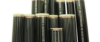
Types of photocells
The main and rather difficult task is to find and buy photovoltaic converters. They are silicon wafers that convert solar energy into electricity. Photovoltaic cells are divided into two types: monocrystalline and polycrystalline. The former are more efficient and have a high efficiency - 20-25%, and the latter are only up to 20%. Polycrystalline solar cells are bright blue and less expensive.And mono can be distinguished by its shape - it is not square, but octagonal, and the price for them is higher.
If the soldering does not work very well, then it is recommended to purchase ready-made photocells with conductors to connect the solar battery with your own hands. If you are confident that you will be able to solder the elements yourself without damaging the converter, you can purchase a set in which the conductors are attached separately.
Growing crystals for solar cells on your own is a rather specific job, and it is almost impossible to do it at home. Therefore, it is better to buy ready-made solar cells.
Connection options
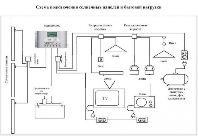
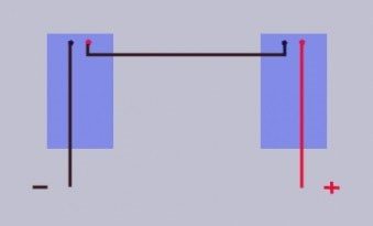
There are no questions when connecting one panel: minus and plus are connected to the corresponding connectors of the controller. If there are many panels, they can be connected:
- in parallel, i.e. we connect the terminals of the same name and, having received a voltage of 12V at the output;
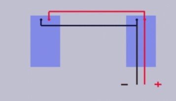
- sequentially, i.e. connect the plus of the first with the minus of the second, and the remaining minus of the first and plus of the second to the controller. The output will be 24 V.
- serial-parallel, i.e. use a mixed connection. It implies such a scheme that several groups of batteries are interconnected. Inside each of them, the panels are connected in parallel, and the groups are connected in series. This output circuit provides the most optimal performance.
To understand in more detail with the connection of alternative sources in the house, the video will help:
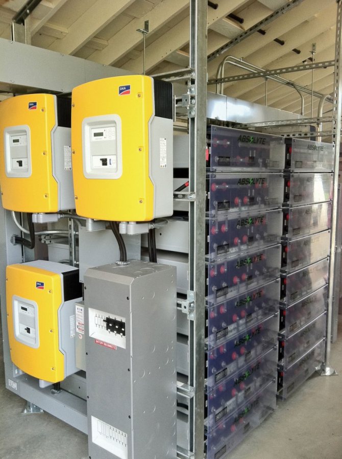
Such power plants with the help of rechargeable batteries accumulate the charge of the Sun for the house and store it, reserving it in battery banks. In America, Japan, European countries, hybrid power supply is often used.
That is, two circuits work, one of which serves low-voltage equipment powered by 12 V, the other circuit is responsible for the uninterrupted supply of energy to high-voltage equipment operating from 230 V.
How to connect solar panels to the maximum using the capabilities of all elements
Mixed backup connection scheme. They will depend on the dimensions of the panels themselves and their number.
Now there is little to do.
With the same characteristics, the next type of panels - thin-film, will require a larger area for installation in the house. Of course, at your own peril and risk, you can connect the panel directly and the battery will be charged, but such a system should be supervised.
If the house is in the shadow of other buildings, then the installation of solar panels is advisable unless only polycrystalline, and then the efficiency will be reduced. In all cases, there should be no shading. Natural blowing of the battery will help to solve this problem. All these factors must be taken into account when choosing an installation site and install panels according to the most convenient option.
Of course, at your own peril and risk, you can connect the panel directly and the battery will be charged, but such a system should be supervised. This is interesting: Many of the standard radio components can also generate electricity when exposed to bright light.
At this stage, it is important not to confuse the back of the panel with the front. This is the most important point, since their productivity, and therefore the amount of electricity generated, will depend on whether the panels are in the shade of other buildings or trees.
When several panels are connected in series, the voltage of all panels will add up. The frame is assembled using bolts with a diameter of 6 and 8 mm. There will be no voltage change in this case.
A mixed connection scheme is often used. It turns out that correctly installed solar panels will work with the same performance both in winter and in summer, but under one condition - in clear weather, when the sun gives off the maximum amount of heat. It is recommended to mount the photocells on the long side to avoid damage, individually choosing the method: the bolts are fastened through the frame holes, clamps, etc. It can be fixed with a thin layer of silicone sealant, but it is better not to use epoxy for these purposes, since it will be extremely difficult to remove the glass in case of repair work and not damage the panels.
Solar panels. How to make a cheap and efficient solar power plant.
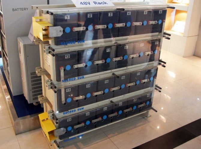
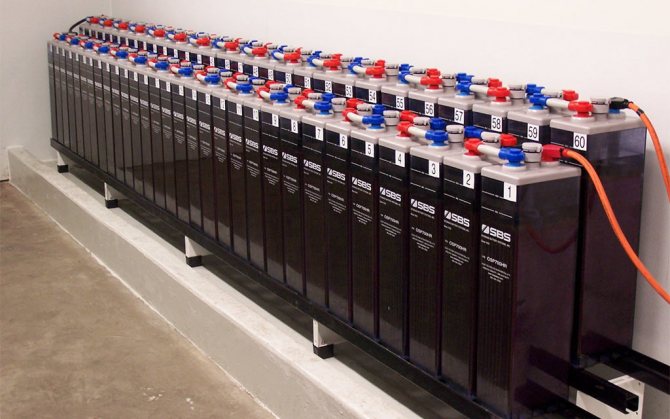
What does the battery give
Storage batteries, abbreviated as accumulators, are capable of fulfilling the deficit of the electricity generated by the installation when the sun's rays are insufficient for its full functioning. This becomes possible due to continuous chemical and physical processes that provide multiple charging cycles.
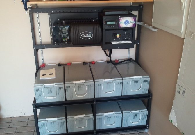
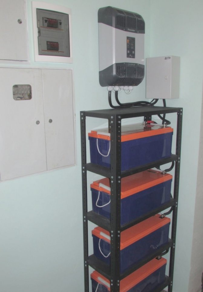
The photo shows that solar batteries do not differ from standard models outwardly, but they have more power and improved performance.
Stages of connecting panels to SES equipment
Connecting solar panels is a step-by-step process that can be performed in different order. Usually, the modules are connected to each other, then a set of equipment and batteries are assembled, after which the panels are connected to the devices. This is a convenient and safe option that allows you to check the correct connection of all elements before energizing. Let's take a closer look at these stages:
To battery
Let's figure out how to connect a solar battery to a battery.
Attention! First of all, it is necessary to clarify - they do not use direct connection of panels to the battery. Uncontrolled energy generation is dangerous for the batteries and can cause both over-consumption and over-charging. Both situations are fatal, as they can permanently disable the battery.
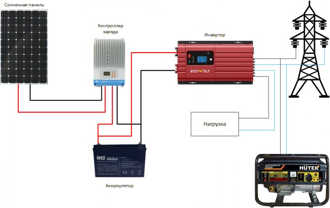
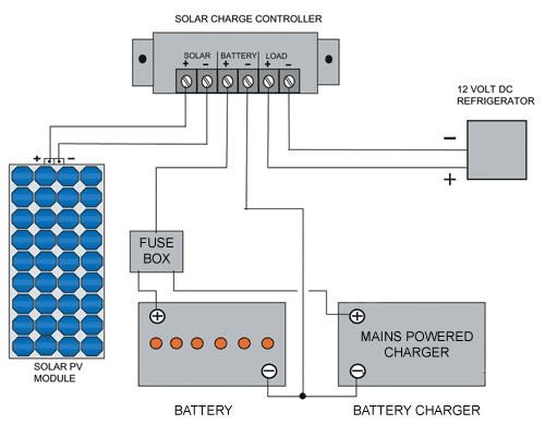
Therefore, between the photovoltaic cells and batteries, a controller must be installed, which provides a regular mode of charging and energy output. In addition, an inverter is usually installed at the output of the controller in order to be able to convert the stored energy into a standard voltage of 220 V 50 Hz. This is the most successful and efficient scheme, which allows the batteries to give or receive a charge in the optimal mode and not exceed their capacity.
Before connecting the solar panel to the battery, it is necessary to check the parameters of all system components and make sure they match. Failure to do so could result in the loss of one or more instruments.
Sometimes a simplified scheme for connecting modules without a controller is used. This option is used in conditions when the current from the panels will certainly not be able to create an overcharge of the batteries. Usually this method is used:
- in regions with short daylight hours
- low position of the sun above the horizon
- low-power solar panels that are not able to provide an excess charge of the battery
When using this method, it is necessary to secure the complex by installing a protective diode. It is placed as close to the batteries as possible and protects them from short circuits. It is not scary for the panels, but for the battery it is very dangerous. In addition, if the wires melt, a fire can start, which poses a danger to the whole house and people. Therefore, providing reliable protection is the primary task of the owner, the solution of which must be completed before the kit is put into operation.
To the controller
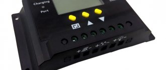
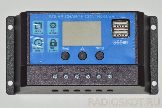
The second method is often used by owners of private or country houses to create a low-voltage lighting network. They purchase an inexpensive controller and connect solar panels to it. The device is compact, comparable in size to a medium-sized book. It is equipped with three pairs of pins on the front panel. Solar modules are connected to the first pair of contacts, a battery is connected to the other, and lighting or other low-voltage consumption devices are connected to the third pair.
First, the first pair of terminals is supplied with a voltage of 12 or 24 V from the batteries. This is a test stage, it is needed to determine the operability of the controller. If the device has correctly determined the amount of battery charge, proceed to the connection.
Important! The solar modules are connected to the second (central) pair of contacts. It is important not to reverse the polarity, otherwise the system will not work.
Low-voltage lamps or other consumption devices powered by 12 (24) V DC are connected to the third pair of contacts. You cannot connect such a kit with anything else. If you need to provide power to household appliances, you need to assemble a fully functional set of equipment - a private SES.
To inverter
Let's take a look at how to connect a solar panel to an inverter.
It is only used to power standard consumers requiring 220 VAC. The specificity of using the device is such that it has to be connected in the last turn - between the battery pack and the end consumers of energy.
The process itself does not constitute any complexity. The inverter comes with two wires, usually black and red ("-" and "+"). There is a special plug at one end of each wire, and at the other end there is a crocodile clip for connecting to the battery terminals. The wires are connected to the inverter according to the color indication, then connected to the battery.
What is the battery
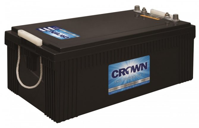
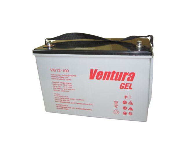
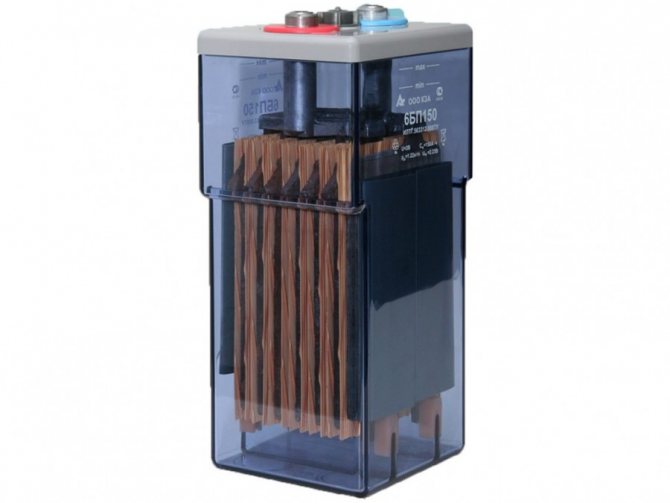
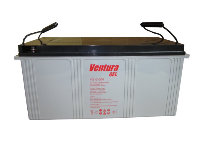
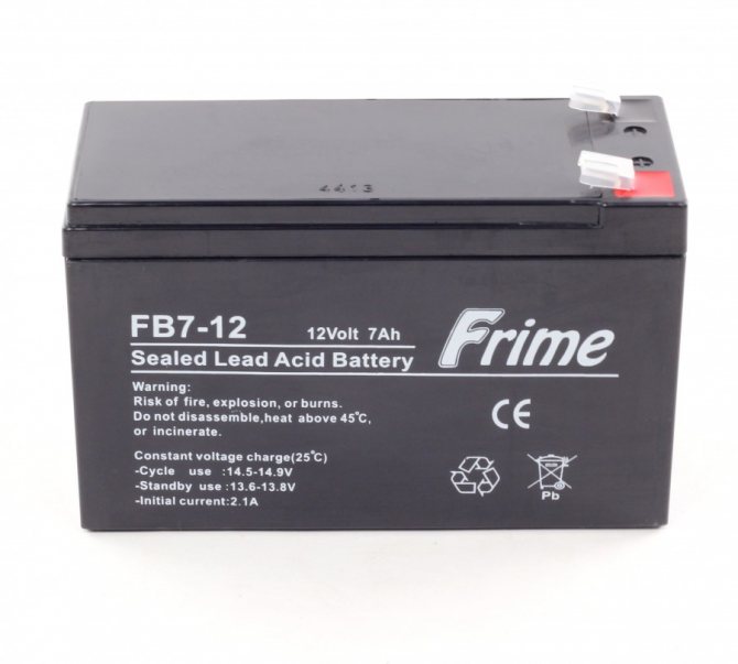
Rechargeable devices are presented in a wide range, so it is not surprising that a logical question arises: which solar batteries are considered more efficient?
In fact, any equipment can be connected to the ultraviolet panel, the main thing is that the accumulated energy supply can provide all connected devices and lighting in a critical situation. For this, it is important to take into account the technical parameters depending on the type, model and brand of the battery.
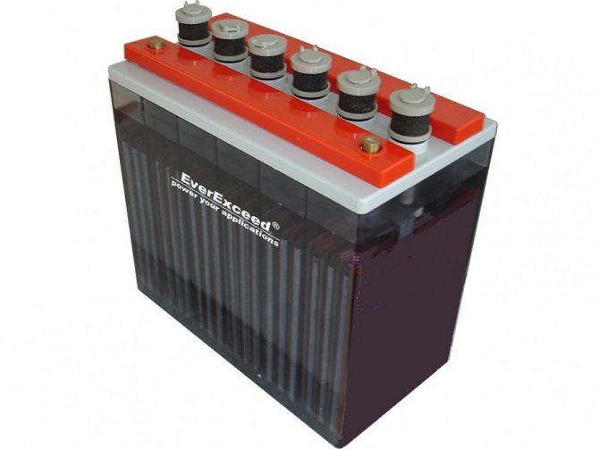
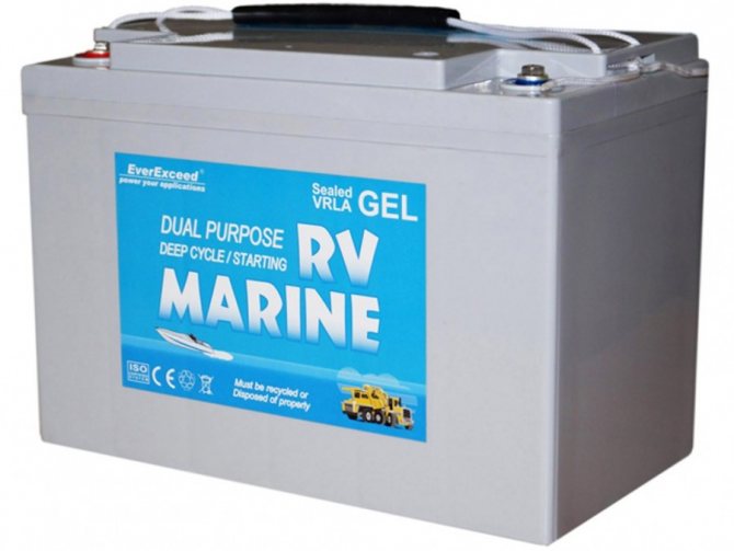
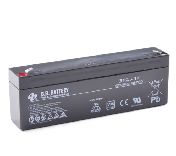
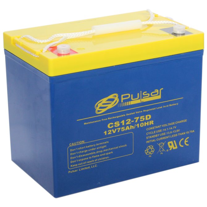
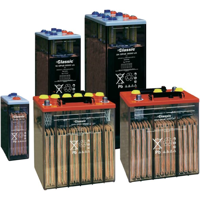
The most popular use of the following types of solar batteries, which have both strengths and weaknesses:
Starter motors are considered the most reliable and durable option, with high efficiency and low self-maintenance costs. Such a battery does not need regular maintenance, so they are often used at stations operating remotely from settlements or in harsh conditions. Of the "minuses" - the need to provide good ventilation at the installation site.
Batteries with spreading plates also do not require constant maintenance, do not need ventilation and are able to deliver the accumulated current for a long time. However, there are also negative aspects: high cost, short service life.
AGM systems are one of the best options because they are economical, compact, have a high charge level, five years of operation, fast replenishment and the ability to withstand up to eight hundred recharge cycles. True, the device does not tolerate an incomplete charge.
Gel also have excellent characteristics: resistance to discharge, autonomous operation, low cost and low energy losses during operation.
Filling devices require an annual check of the electrolyte level, but they have the highest indicators of energy reserves, resistance to charging cycles, but their high cost is justified only at large power plants.
Car batteries are also often installed in self-made units, their main advantages are economy and the ability to work at any charge level. Used devices are often used, which often fail and require replacement.
Economic feasibility
The payback period for solar panels is easy to calculate.Multiply the daily amount of energy produced per day by the number of days per year and by the service life of the panels without derating - 30 years. The electrical installation considered above is capable of generating an average of 52 to 100 kWh per day, depending on the length of daylight hours. The average value is about 64 kWh. Thus, in 30 years, the power plant, in theory, should generate 700 thousand kWh. With a one-part rate of 3.87 rubles. and the cost of one panel is about 15,000 rubles, the costs will pay off in 4-5 years. But the reality is more prosaic.
The fact is that the December values of solar radiation are less than the average annual by about an order of magnitude. Therefore, fully autonomous operation of a power plant in winter requires 7-8 times more panels than in summer. This significantly increases investment, but reduces the payback period. The prospect of introducing a “green tariff” looks quite encouraging, but even today it is possible to conclude an agreement for the supply of electricity to the grid at a wholesale price that is three times lower than the retail tariff. And even this is enough to profitably sell 7-8 times the surplus of generated electricity in the summer.