Calculation of performance for heating air of a certain volume
Determine the mass flow rate of heated air
G
(kg / h) =
L
x
R
Where:
L
- volumetric amount of heated air, m3 / hour
p
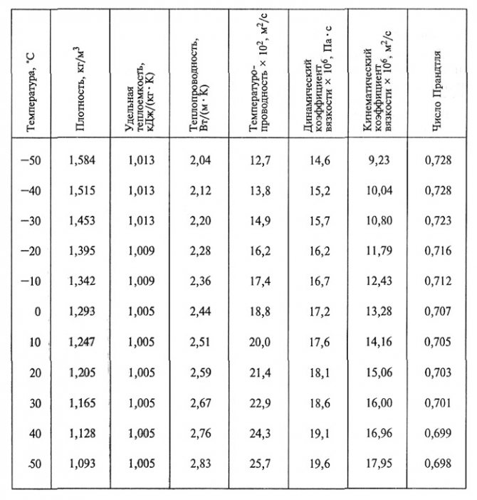
- air density at average temperature (the sum of the air temperature at the inlet and outlet from the heater is divided by two) - the table of density indicators is presented above, kg / m3
Determine the heat consumption for heating air
Q
(W) =
G
x
c
x (
t
con -
t
beginning)
Where:
G
- mass air flow rate, kg / h s - specific heat capacity of air, J / (kg • K), (the indicator is taken from the temperature of the incoming air from the table)
t
start - air temperature at the inlet to the heat exchanger, ° С
t
con is the temperature of the heated air at the outlet of the heat exchanger, ° С

The initial data for the selection of air heaters are the consumption of heated air G
, kg / h, air temperature at the inlet to the heater
t1
, ° С, and at the exit from it
t2,
° С, as well as the water temperature at the inlet to the heater
T1,
° С, and at the exit from it
T2, ° C.
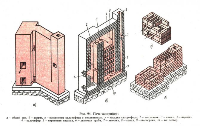
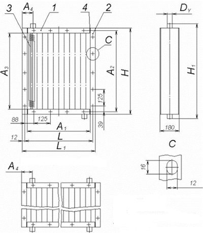
The purpose of the selection of heaters is to determine their number and size in the installation, aerodynamic and hydraulic resistance. The heaters KVS-P, KVB-P, KSk-3, KSk-4 [14] and VNV.243 are recommended for installation. These guidelines provide the necessary data for VNV.243 heaters from VEZA Co LTD (Fig. 10.1 and Table 10.1).
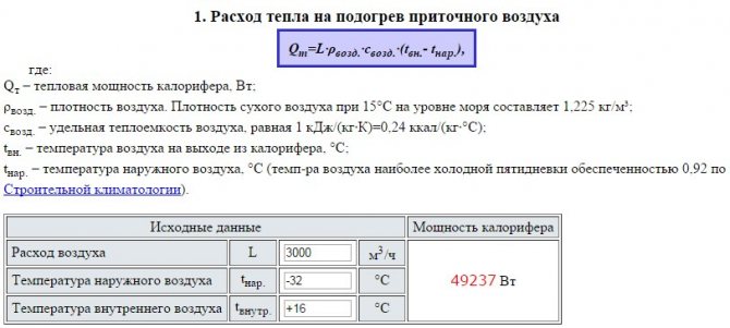
The selection of the installation is carried out in the following order.
1. Determine the heat consumption for heating the air, W:
(10.1)
where is the mass heat capacity of air, taken equal to 1.005 kJ / (kg · K).
2. The approximate mass velocity of air movement through the air heater is taken from the range.
3. In accordance with the accepted value of the mass velocity, the approximate area of the free cross-section of the air heater for the passage of air is determined, m2:
(10.2)
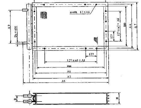
Fig. 10.1 Overall and connecting dimensions of VNV heaters
4. The type and number of the heater is adopted. For the accepted standard size of the air heater according to the reference literature [14], the following parameters are selected:
- heating surface area, Fн, m2
Is the area of the free cross-section through the air, fzh, s. , m2
-area of the free cross-section for the coolant, ftr, m2
For heaters VNV technical characteristics are given in tables 10.2; 10.3; 10.4 and 10.5.
5.The number of air heaters installed in parallel is calculated:
(10.3)
Table 10.1
Overall and connecting dimensions of VNV heaters
| Air heater number | Dimensions, mm | number | ||||||||||
| but | BUT, | A2 | Az | A4 | b | A6 | A7 | A8 | A9 | n | n1 | n2 |
6.The actual mass air velocity through the heater is determined:
(10.4)
7. Determine the amount of heat carrier passing through the heating installation, kg / h:
(10.5)
where w is the heat capacity of water, taken as 4.19 kJ / (kg · K).
8. The method of piping the heaters by the heat carrier in the heater installation is selected and the speed of movement of the heat carrier in the tubes of the heater is calculated, m / s:
(10.6)
where ρw is the density of water taken 1000 kg / m3;
n is the number of heaters installed in parallel on the water.
Table 10.2
Technical data of VNV heaters with one row of tubes
| Air heater designation | Air heater number | Heat exchange surface area on the air side, m2 | Frontal section area, m2 | Sectional area for the passage of the coolant, m2 | Tube length in one stroke | Weight, kg |
| VNV243-053-037- 1-1.8-6 VNV243-053-037-1-2.5-6 VNV243-053-037- 1-4.0-6 | 4,390 3,190 2,040 | 0,210 0,210 0,210 | 0,000095 0,000095 0,000095 | 3,498 3,498 3,498 | 4,27 3,78 3,51 | |
| VNV243-065-037-1-1.8-6 VNV243-065-037- 1-2.5-6 VNV243-065-037-1-4.0-6 | 5,420 2,520 | 0,245 0,245 0,245 | 0,000095 0,000095 0,000095 | 4,323 4,323 4,323 | 4,81 4,27 3,89 | |
| VNV243-078-037-1-1.8-6 VNV243-078-037-1 -2.5-6 VNV243-078-037-1-4.0-6 | 6,470 4,700 3,010 | 0,295 0,295 0,295 | 0,000095 0,000095 0,000095 | 5,148 5,148 5,148 | 5,29 4,70 4,32 | |
| VNV243-090-037-1-1.8-2 VNV243-090-037-1-2.5-2 VNV243-090-037-1-4.0-2 | 7,500 5,450 3,490 | 0,342 0,342 0,342 | 0,00019 0,00019 0,00019 | 1,991 1,991 1,991 | 5,78 5,18 4,75 | |
| Continuation of table 10.2 | ||||||
| VNV243-115-037-1-1.8-2 VNV243-115-037-1-2.5-2 VNV243-115-037-1-4.0-2 | 9,580 6,980 4,450 | 0,436 0,436 0,436 | 0,00019 0,00019 0,00019 | 2,541 2,541 2,541 | 6,97 5,99 5,40 | |
| VNV243-053-050- 1-1.8-4 VNV243-053-050- 1-2.5-4 VNV243-053-050- 1-4.0-4 | 7,290 5,290 3,390 | 0,267 0,267 0,267 | 0,00019 0,00019 0,00019 | 2,332 2,332 2,332 | 6,37 5,83 5,35 | |
| VNV243-065-050-1-1.8-4 VNV243-065-050-1-2.5-4 VNV243-065-050- 1-4.0-4 | 9,000 6,540 4,180 | 0,329 0,329 0,329 | 0,00019 0,00019 0,00019 | 2,882 2,882 2,882 | 7,45 6,59 5,99 | |
| VNV243-078-050- 1-1.8-4 VNV243-078-050- 1-2.5-4 VNV243-078-050- 1-4.0-4 | 10,740 7,800 5,000 | 0,392 0,392 0,392 | 0,00019 0,00019 0,00019 | 3,432 3,432 3,432 | 8,05 7,18 6,53 | |
| IBHB243-090-050- 1-1.8-4 VNV243-090-050-1-2.5-4 VNV243-090-050-1-4.0-4 | 12,450 9,050 5,800 | 0,455 0,455 0,455 | 0,00019 0,00019 0,00019 | 3,982 3,982 3,982 | 9,07 7,94 7,18 | |
| VNV243-116-050-1-1.8-2 VNV243-116-050-1-2.5-2 VNV243-116-050-1-4.0-2 | 15,890 11,580 7,390 | 0,581 0,581 0,581 | 0,000475 0,000475 0,000475 | 2,541 2,541 2,541 | 10,64 9,23 8,32 | |
| End of Table 10.2 | ||||||
| VNV243-116-100-1-1.8-2 VNV243-116-100- 1-2.5-2 VNV243-116-100-1-4.0-2 | 45,42 33,03 21,12 | 1,660 1,660 1,660 | 0,00095 0,00095 0,00095 | 3,641 3,641 3,641 | 38,88 34,72 31,81 | |
| VNV243-116-150-1-1.8-2 VNV243-116-150-1-2.5-2 VNV243-116-150-1-4.0-2 | 68,06 49,5 31,65 | 2,487 2,487 2,487 | 0,001425 0,001425 0,001425 | 3,641 3,641 3,641 | 57,78 51,95 47,57 |
Note. In Fig. 10.1 H = 55
m,
IN
= 55 mm.
Table 10.3
Technical data of VNV heaters with two rows of tubes
| Air heater designation | Air heater number | Heat exchange surface area on the air side, m2 | Frontal section area, m2 | Sectional area for the passage of the coolant, m2 | Tube length in one stroke | Weight, kg |
| VNV243-053-037-2 -1.8-6 VNV243-053-037-2-2.5-6 | 8,820 6,400 | 0,210 0,210 | 0,00019 0,00019 | 3,498 3,498 | 7,900 7,000 | |
| VNV243-065-037-2-1.8-6 VNV243-065-037-2 -2.5-6 | 10,890 7,920 | 0,245 0,245 | 0,00019 0,00019 | 4,323 4,323 | 8,900 7,900 | |
| VNV243-078-037-2-1.8-6 VNV243-078-037-2 -2.5-6 | 12,990 9,440 | 0,295 0,295 | 0,00019 0,00019 | 5,148 5,148 | 9,800 8,700 | |
| VNV243-090-037-2-1.8-2 VNV243-090-037-2-2.5-2 | 15,060 10,950 | 0,342 0,342 | 0,000285 0,000285 | 3,982 3,982 | 10,700 9,600 | |
| VNV243-115-037-2-1.8-2 VNV243-115-037-2-2.5-2 | 19,240 14,010 | 0,436 0,436 | 0,000285 0,000285 | 5,082 5,082 | 12,900 11,100 | |
| VNV243-053-050-2 -1.8-4 VNV243-053-050-2 -2.5-4 | 14,640 10,620 | 0,267 0,267 | 0,000285 0,000285 | 3,498 3,498 | 11,800 10,800 | |
| End of Table 10.3 | ||||||
| VNV243-065-050-2-1.8-4 VNV243-065-050-2-2.5-4 | 18,080 13,140 | 0,329 0,329 | 0,000285 0,000285 | 4,323 4,323 | 13,800 12,200 | |
| VNV243-078-050-2 -1.8-4 VNV243-078-050-2 -2.5-4 | 21,560 15,660 | 0,392 0,392 | 0,000285 0,000285 | 5,148 5,148 | 14,900 13,300 | |
| BHB243-090-050-2 -1.8-4 VNV243-090-050-2-2.5-6 | 25,000 18,180 | 0,455 0,455 | 0,000475 0,000285 | 3,982 5,973 | 16,800 14,700 | |
| VNV243-116-050-2-1.8-4 VNV243-116-050-2-2.5-4 | 31,920 23,260 | 0,581 0,581 | 0,000475 0,000475 | 5,082 5,082 | 19,700 17,100 | |
| VNV243-116-100-2-1.8-2 VNV243-116-100-2 -2.5-2 | 91,240 66,350 | 1,660 1,660 | 0,001901 0,001901 | 3,641 3,641 | 72,000 64,300 | |
| VNV243-116-150-2-1.8-2 VNV243-116-150-2-2.5-2 | 136,710 99,420 | 2,487 2,487 | 0,002851 0,002851 | 3,641 3,641 | 107,000 96,200 |
Note. In Fig. 10.1 H
= 55 m,
B =
55 mm.
Table 10.4
Technical data of VNV heaters with three rows of tubes
| Air heater designation | Air heater number | Heat exchange surface area on the air side, m2 | Frontal section area, m2 | Sectional area for the passage of the coolant, m2 | Tube length in one stroke | Weight, kg |
| VNV243-053-053-3-1.8-6 | 13,250 | 0,210 | 0,0002850 | 3,498 | 1,10 | |
| VNV243-065-037-3-1.8-6 | 16,360 | 0.245 | 0,0002850 | 4,323 | 13,70 | |
| VNV243-078-037-3-1.8-6 | 19,520 | 0,295 | 0,0002850 | 5,148 | 14,80 | |
| VNV243-090-037-3-1.8-4 | 22,630 | 0,342 | 0,0003800 | 3,982 | 16,20 | |
| VNV243-115-037-3-1.8-4 | 28,890 | 0,436 | 0,0003800 | 5,082 | 19,30 | |
| VNV243-053-050-3-1.8-6 | 21,990 | 0,267 | 0,0004750 | 3,498 | 17,10 | |
| VNV243-065-050-3-1.8-6 | 27,160 | 0,329 | 0,0004750 | 4,323 | 19,50 | |
| VNV243-078-050-3-1.8-6 | 32,390 | 0,92 | 0,0004750 | 5,148 | 22,10 | |
| VNV243-090-050-3-1.8-6 | 37,550 | 0,455 | 0,0004750 | 5,973 | 24,10 | |
| VNV243-116-050-3-1.8-4 | 47,950 | 0,581 | 0,0006650 | 5,082 | 28,80 | |
| VNV243-165-100-3-1.8-2 | 137,060 | 1,660 | 0,0028510 | 3,641 | 102,50 | |
| VNV243-165-150-3-1.8-2 | 205,370 | 2,487 | 0,0042760 | 3,641 | 152,1 |
Note. In Fig. 10.1 H = 80
mm ,,
IN
= 75 mm.
Table 10.5
Technical data of VNV heaters with four rows of tubes
| Air heater designation | Air heater number | Heat exchange surface area on the air side, m2 | Frontal section area, m2 | Sectional area for the passage of the coolant, m2 | Tube length in one stroke | Weight, kg |
| VNV243-053-053-4-1.8-6 | 17,68 | 0,210 | 0,00038 | 3,498 | 15,10 | |
| VNV243-065-037-4-1-8-6 | 21,83 | 0.245 | 0,00038 | 4,323 | 17,50 | |
| VNV243-078-037-4-1-8-6 | 26,04 | 0,295 | 0,00038 | 5,148 | 19,10 | |
| VNV243-090-037-4-1-8-4 | 30,19 | 0,342 | 0,00057 | 3,982 | 21,50 | |
| BHB243-115-037-4-1-8-4 | 38,55 | 0,436 | 0,00057 | 5,082 | 24,80 | |
| VNV243-053-050-4-1-8-6 | 29,35 | 0,267 | 0,000665 | 3,498 | 22,40 | |
| VNV243-065-050-4-1-8-6 | 36,23 | 0,329 | 0,000665 | 4,323 | 26,20 | |
| VNV243-078-050-4-1-8-6 | 43,22 | 0,92 | 0,000665 | 5,148 | 31,00 | |
| VNV243-090-050-4-1-8-6 | 50,11 | 0,455 | 0,000665 | 5,973 | 32,50 | |
| VNV243-116-050-4-1-8-4 | 63,98 | 0,581 | 0,00095 | 5,082 | 37,20 | |
| VNV243-165-100-4-1-8-6 | 182,87 | 1,660 | 0,003801 | 3,641 | 142,1 | |
| VNV243-165-150-3-1-8-2 | 274,02 | 2,487 | 0,005702 | 3,641 | 210,5 |
Note. In Fig. 10.1 H
= 110 m,
B =
100 mm.
9. The heat transfer coefficient of heaters is determined, W / (m2.K):
For KVS-p (10.7)
| for KVB-p | (10.8) |
for KSK-3 (10.9)
| for KSK -4 | (10.10) |
for VNV 243 (10.11)
Where but
- empirical coefficient (see table. 10.6).
Table 10.6
Values of calculated coefficients for VNV air heaters
| Number of rows of tubes | |||||||
| Plate pitch | 1,8 | 2,5 | 1,8 | 2,5 | 1,8 | 1,8 | |
| but | 20,94 | 21,68 | 23,11 | 20,94 | 21,68 | 20,94 | 20,94 |
| b | 2,104 | 1,574 | 1,034 | 4,093 | 3,055 | 6,044 | 7,962 |
| t | 1,64 | 1,74 | 1,81 | 1,65 | 1,72 | 1,66 | 1,59 |
10.The required heating surface of the air heater is determined, m2:
(10.12)
11. The reserve of the heating surface area is determined:
(10.13)
12. According to the table. 4.38 [14] and the formulas corresponding to a certain type of air heater determine the air resistance of the air heater, Pa, and the resistance when water passes through the installation [14].
Calculation of the frontal section of the device required for the passage of the air flow
Having decided on the required thermal power for heating the required volume, we find the frontal section for the air passage.
Frontal section - working inner section with heat-transfer tubes, through which flows of the forced cold air pass directly.
f
(sq.m.) =
G
/
v
Where:
G
- mass air consumption, kg / h
v
- air mass velocity - for finned air heaters it is taken in the range 3 - 5 (kg / m.kv • s). Allowable values - up to 7 - 8 kg / m.kv • s
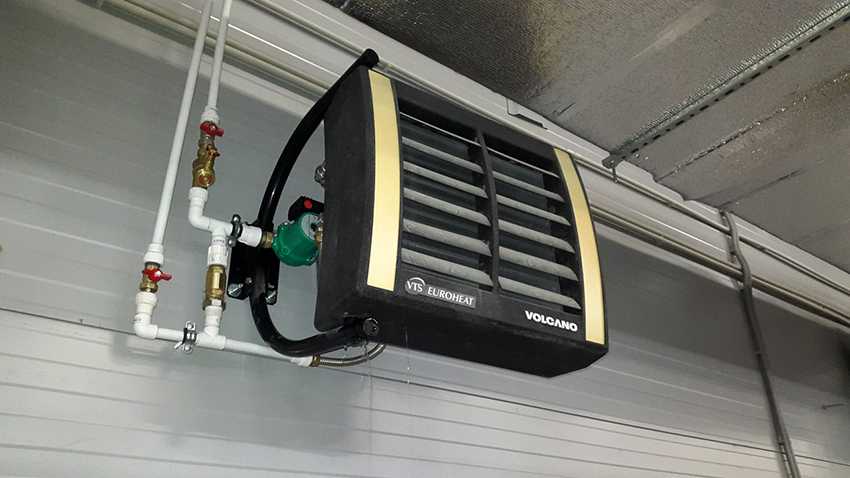
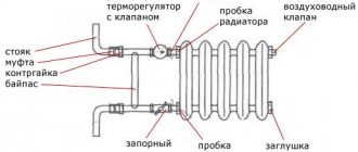
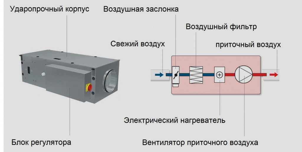
What is a heater and what is it for
It is a kind of heat exchanger, in which the heat source is air flows in contact with heating elements. The device warms up the supply air in ventilation systems and drying equipment.
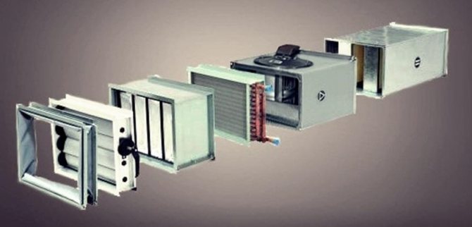
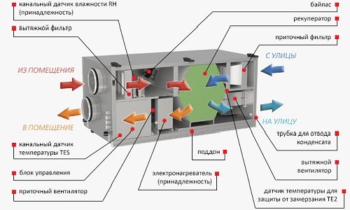
The diagram shows the place of the heater in the duct ventilation unit
The mounted device can be presented as a separate module or be part of a monoblock ventilation unit. The scope of application is presented:
- initial heating of air in supply ventilation systems with air flow from the street;
- secondary heating of air masses during recuperation in supply and exhaust systems that recover heat;
- secondary heating of air masses inside individual rooms to ensure an individual temperature regime;
- heating the air to supply it to the air conditioner in winter;
- backup or additional heating.
The energy efficiency of a duct air heater of any design is determined by the coefficient of heat output under conditions of certain energy costs, therefore, with significant indicators of heat output, the device is considered to be highly efficient.
The piping in the supply ventilation system of the regulating reinforcement cage is carried out by means of two-way valves in the city network, as well as three-way valves when using a boiler room or boiler. With the installed strapping unit, the performance of the equipment used is easily controlled, and the risk of freezing in winter is minimized.
Calculating Mass Velocity Values
Find the actual mass velocity for the air heater
V
(kg / m.kv • s) =
G
/
f
Where:
G
- mass air consumption, kg / h
f
- the area of the actual frontal section taken into account, sq.
Expert opinion
Important!
Can't handle the calculations yourself? Send us the existing parameters of your room and the requirements for the heater. We will help you with the calculation. Alternatively, look at existing questions from users on this topic.
Calculation of room ventilation depending on the number of people
The second relatively simple way to calculate the performance of a ventilation system is by the number of people in the room. In this case, it is enough to enter the number of users into the ventilation calculator and indicate the degree of their activity.
Calculations are carried out according to the formula
L = N x Lnorm
Where L is the required capacity of the ventilation system, m3 / h;
N is the number of people;
Lnorm - the consumption of the air mixture per person, according to the standards (volume).
The last indicator is taken in accordance with sanitary and hygienic standards:
- calmness (rest, sleep) - 20 m3 / h;
- moderate activity - 40 m3 / h;
- active activity (physical work, training) - 60 m3 / h.
Thus, for a room with the same dimensions as in the previous example of ventilation calculation (20 square meters) with simultaneous moderate activity of 5 people (office work), system power will be required
L = 5 x 40 = 200 cbm.
If we are not talking about a private house, but about a public institution, you should be guided by other indicators.
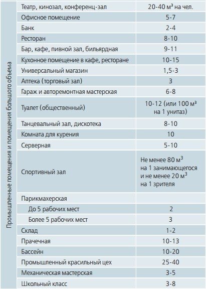
However, for such premises, the ventilation performance is calculated individually, during the design of the system (or the building as a whole), and the air exchange rate is considered only an additional, test indicator.
Calculation of the thermal performance of the air heater
Calculation of the actual heat output:
q
(W) =
K
x
F
x ((
t
in +
t
out) / 2 - (
t
start +
t
con) / 2))
or, if the temperature head is calculated, then:
q
(W) =
K
x
F
x
average temperature head
Where:
K
- heat transfer coefficient, W / (m.kv • ° C)
F
- heating surface area of the selected heater (taken according to the selection table), sq.
t
in - water temperature at the inlet to the heat exchanger, ° С
t
out - water temperature at the outlet of the heat exchanger, ° С
t
start - air temperature at the inlet to the heat exchanger, ° С
t
con is the temperature of the heated air at the outlet of the heat exchanger, ° С
Online calculator for calculating the power of the heater
The effective operation of ventilation depends on the correct calculation and selection of equipment, since these two points are interconnected. To simplify this procedure, we have prepared for you an online calculator for calculating the power of the heater.
The selection of the power of the heater is impossible without determining the type of fan, and the calculation of the internal air temperature is useless without the selection of the heater, recuperator and air conditioner. Determining the parameters of the duct is impossible without calculating the aerodynamic characteristics.The calculation of the capacity of the ventilation heater is carried out according to the standard parameters of the air temperature, and mistakes at the design stage lead to an increase in costs, as well as the inability to maintain the microclimate at the required level.
Air heater (more professional name "duct heater") is a universal device used in internal ventilation systems to transfer heat energy from heating elements to air passing through a system of hollow tubes.
Duct heaters differ in the way of energy transfer and are divided into:
- Water - energy is transmitted through pipes with hot water, steam.
- Electric - heating elements, receiving energy from the central power supply network.
There are also heaters that work on the recuperation principle: this is the recovery of heat from the room by transferring it to the supply air. The recovery is carried out without contact between the two air media.
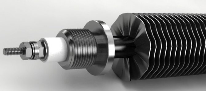
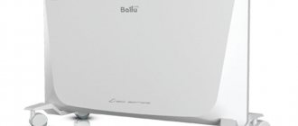
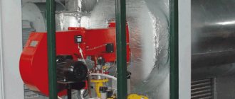
Electric heater
The basis is a heating element made of wire or spirals, an electric current passes through it. Cold street air is passed between the spirals, it heats up and is supplied to the room.
The electric air heater is suitable for servicing low-power ventilation systems, since no special calculation is required for its operation, since all the necessary parameters are specified by the manufacturer.
The main disadvantage of this unit is the inertia between the heating threads, which leads to constant overheating, and, as a consequence, the failure of the device. The problem is solved by installing additional expansion joints.
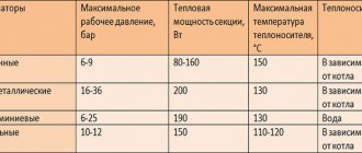
Views
Heating and ventilation technology is represented mainly by water and steam appliances.
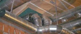
Air flows pass through several system nodes
The preference is most often given to water air heaters, which differ:
- surface shape. They can be smooth-tube and ribbed, plate and spiral-wound;
- the nature of the movement of the heat carrier. Single-pass and multi-pass air heaters.
Depending on the size of the heating surface, all devices of the water and steam type are presented in four models: the smallest (SM), small (M), medium (C) and large (B).
Water
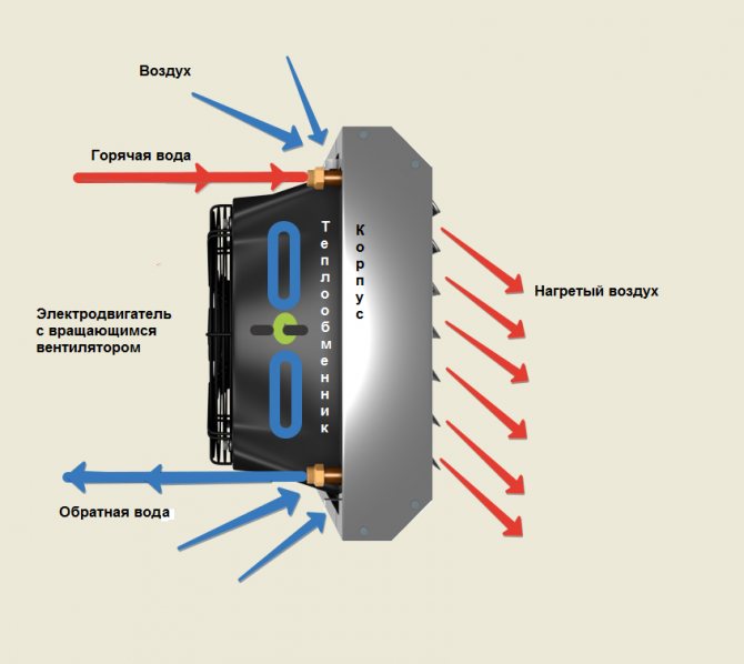
Water-type air heaters provide heating of the air inside the ventilation duct to comfortable temperature indicators by means of the energy of the heat carrier constantly circulating in the radiator part of the equipment. Liquid coolants are not inferior in their basic characteristics to analogs of the electric type, but they differ in increased energy consumption and some complexity of installation, therefore, their installation should be carried out by specialists.
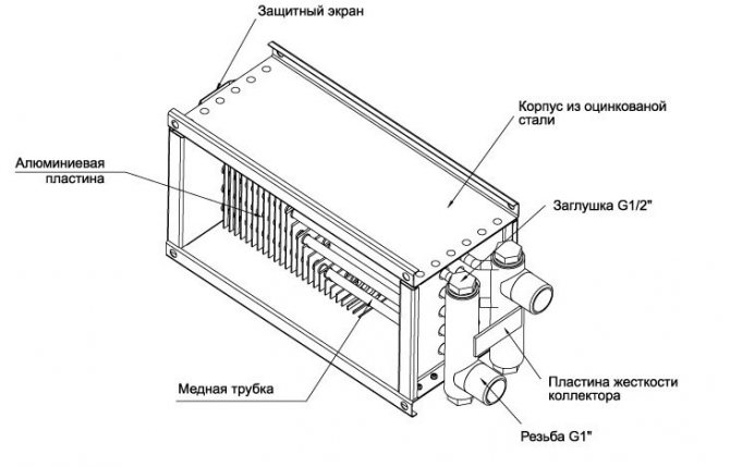
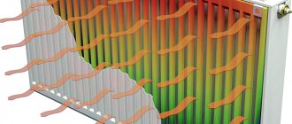
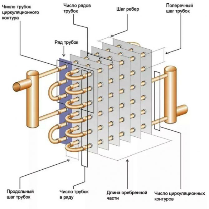
The principle of operation is based on the presence in the structure of the links of an empty copper or copper alloy-based coil, arranged in a checkerboard pattern. Also, the device has aluminum plates designed for heat transfer. A heated liquid, represented by water or glycol solution, moves inside the copper coil, as a result of which heat is transferred to the air flows from the supply system.
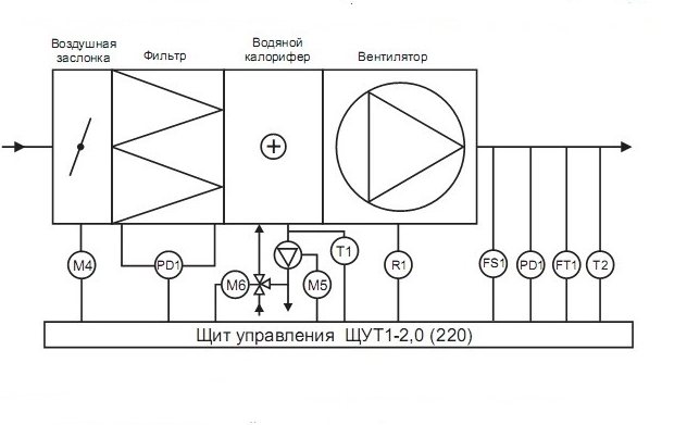
The diagram shows ventilation units with a water filter
The main advantages of water air heaters in ventilation systems can be attributed to the high heating efficiency of large premises, which is due to its design features.
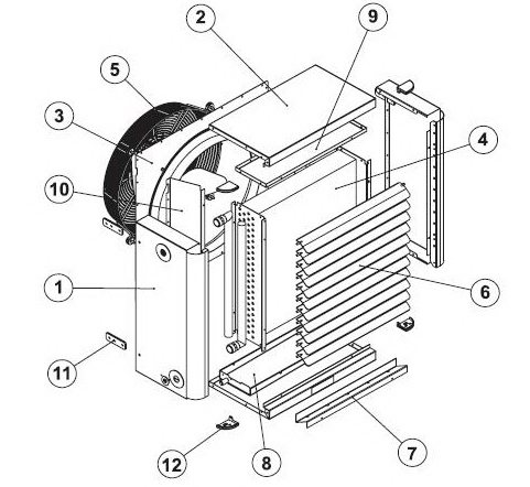
Housing and internal parts of the water heater
- side of the body;
- top and bottom panels of the case;
- ventilation duct on the rear panel;
- heat exchanger;
- motor support grill;
- oriented blades;
- additional tank for condensate;
- main tank for condensate;
- the upper part of the heat exchanger body;
- air duct;
- brackets fixing the device;
- plastic squares.
The main disadvantage is the high risk of freezing of the device in conditions of sharply negative temperatures, which is explained by the presence of water in the system and requires mandatory protection against icing.
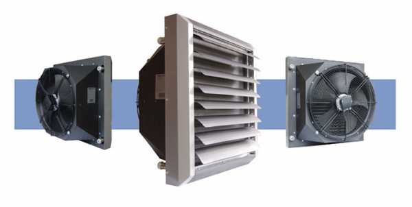
They are represented by metal tubes with a ribbed outer part, which increases the efficiency of heat transfer. Duct heaters, through the pipes of which the heated heat carrier moves, and outside the air masses move and heat up, it is advisable to mount in rectangular ventilation systems.
Steam
They are in demand by industrial enterprises with an excess of steam, which makes it possible to meet the technological needs of the device. The heat carrier in such a device is represented by steam supplied from above, and in the process of its passage through the working elements of the heat exchanger, condensate is formed.
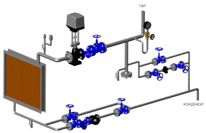
The heat carrier in this type of heater is steam
All currently produced steam heat exchangers are obligatory tested for tightness by means of dry air supplied with a pressure within 30 bar when the device is immersed in a tank filled with warm water.
The advantages of devices in the air conditioning and ventilation system include quick warming up of the room, which is explained by the design of such a device.
Schematic representation of the main components of a steam heater
- board with pipes;
- lateral flap part;
- heating element;
- gasket.
A tangible disadvantage of a steam channel heater is the mandatory presence of equipment that continuously generates steam.
Electric
It is economically feasible to equip the least powerful ventilation systems with conventional electric heaters. The principle of operation of the device is based on the passage of air flows supplied through the supply ventilation system through heating elements that release part of the thermal energy. Heated air is supplied to the room, and protection against any overheating is realized by bimetallic thermal switches.
Such devices do not need at all the connection of too complex or professional communication systems, therefore they are connected to the existing electrical supply lines, which is an undoubted advantage.
It is recommended to equip more powerful ventilation systems with electric heaters
The internal structure is represented by electric tube-type heaters, which ensures the most efficient heat exchange with the surrounding air flows.
- IV - ventilation element for exhaust air;
- PV - ventilation element for supply air;
- PR - plate type heat exchanger;
- KE - electric heating element;
- PF - filtering system for fresh air;
- IF - filtering system for extract air;
- TJ - temperature sensor for supply air;
- TL - temperature sensor for fresh air;
- TA - temperature sensor for extract air;
- M1 - air bypass valve motor;
- M2 - valve for fresh air flows;
- M3 - valve for exhaust air flows;
- PS1 - differential pressure switch for supply air flows;
- PS2 - exhaust type differential pressure switch for air flows.
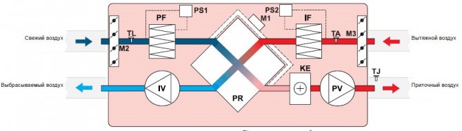
Electric heater includes 14 elements
The use of electrical appliances can only be justified in a ventilated room, the area of which is less than 100–150 m2. Otherwise, the level of electrical energy consumption will be too high.
High-quality ventilation in the house will get rid of dampness and stagnant air. In the next article, you will learn in more detail about the installation of a supply and exhaust type system:.