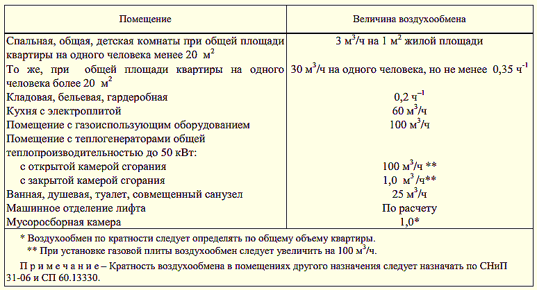
Recommended rates of air exchange rate
During the design of the building, the calculation of each individual section is performed. In production, these are workshops, in residential buildings - apartments, in a private house - floor blocks or separate rooms.
Before installing the ventilation system, it is known what the routes and dimensions of the main lines are, what geometry ventilation ducts are needed, what pipe size is optimal.
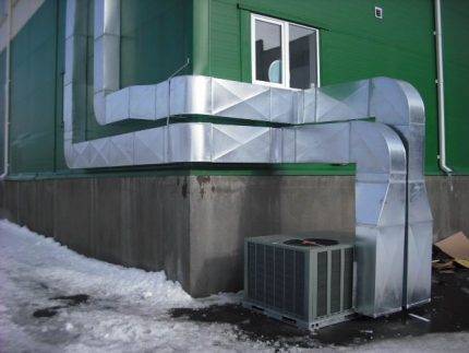
Do not be surprised by the overall dimensions of the air ducts in catering establishments or other institutions - they are designed to remove a large amount of used air
Calculations associated with the movement of air flows inside residential and industrial buildings are classified as the most difficult, therefore, experienced qualified specialists are required to deal with them.
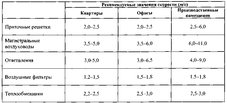
The recommended air speed in the ducts is indicated in SNiP - regulatory state documentation, and when designing or commissioning objects, they are guided by it.
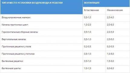
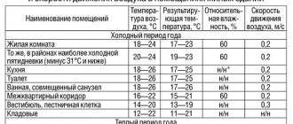
The table shows the parameters that should be adhered to when installing a ventilation system. The numbers indicate the speed of movement of air masses in the places of installation of channels and gratings in generally accepted units - m / s
It is believed that indoor air speed should not exceed 0.3 m / s.
Exceptions are temporary technical circumstances (for example, repair work, installation of construction equipment, etc.), during which the parameters can exceed the standards by a maximum of 30%.
In large rooms (garages, production halls, warehouses, hangars), instead of one ventilation system, two often operate.
The load is divided in half, therefore, the air speed is selected so that it provides 50% of the total estimated volume of air movement (removal of contaminated or supply of clean air).
In the event of force majeure circumstances, it becomes necessary to abruptly change the air speed or to completely stop the operation of the ventilation system.
For example, according to fire safety requirements, the speed of air movement is reduced to a minimum in order to prevent the spread of fire and smoke in adjacent rooms during a fire.
For this purpose, cut-off devices and valves are mounted in the air ducts and in the transition sections.
Calculation method
Initially, it is necessary to calculate the required cross-sectional area of the duct based on the data on its consumption.
- The cross-sectional area of the duct is calculated by the formula
FP = LP / VT
Where
LP
- data on the movement of the required volume of air in a specific area.
VT
- the recommended or permissible air speed in the duct for a certain purpose.
- Having received the required data, the air duct size close to the calculated value is selected. Having new data, the calculation of the real speed of movement of gases in the section of the ventilation system is made, according to the formula:
VФ = LP / FФ
Where
LP
- consumption of the gas mixture.
FF
- the actual cross-sectional area of the selected air duct.
Similar calculations must be carried out for each individual ventilation section.
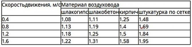
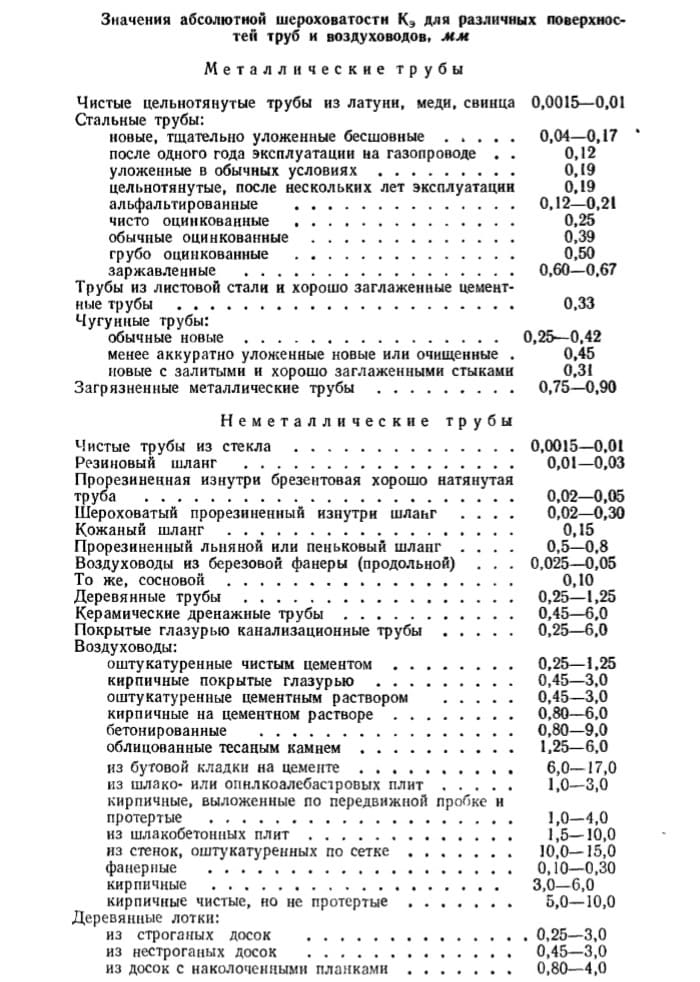
For the correct calculation of the air velocity in the duct, it is necessary to take into account the friction losses and local resistances. One of the parameters affecting the amount of losses is friction resistance, which depends on the roughness of the air duct material.Data on the coefficient of friction can be found in the reference literature.
The subtleties of choosing an air duct
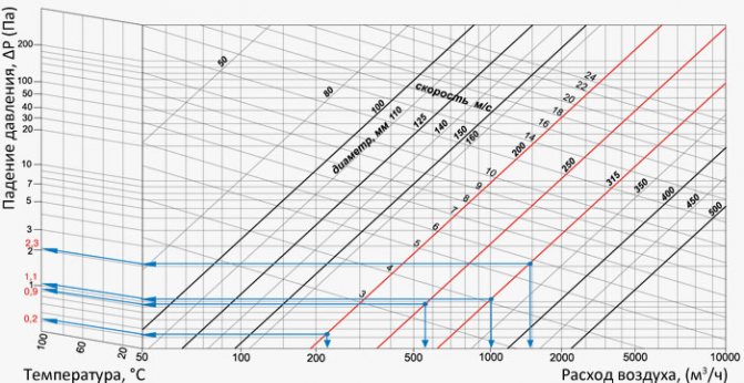
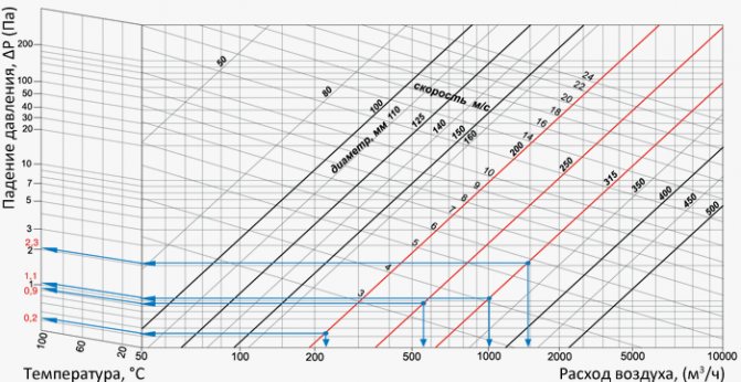
Knowing the results of aerodynamic calculations, it is possible to correctly select the parameters of the air ducts, or rather, the diameter of the round and the dimensions of the rectangular sections.
In addition, in parallel, you can select a device for forced air supply (fan) and determine the pressure loss during the movement of air through the channel.
Knowing the value of the air flow and the value of the speed of its movement, it is possible to determine what section of the air ducts will be required.
For this, a formula is taken that is the opposite of the formula for calculating the air flow: S = L / 3600 * V.
Using the result, you can calculate the diameter:
D = 1000 * √ (4 * S / π)
Where:
- D is the diameter of the duct section;
- S - cross-sectional area of air ducts (air ducts), (m2);
- π - number "pi", a mathematical constant equal to 3.14 ;.
The resulting number is compared with the factory standards approved by GOST, and the products that are closest in diameter are selected.
If it is necessary to choose rectangular rather than round air ducts, then instead of the diameter, determine the length / width of the products.
When choosing, they are guided by an approximate cross-section, using the principle a * b ≈ S and size tables provided by the manufacturers. We remind you that according to the norms, the ratio of width (b) and length (a) should not exceed 1 to 3.
Air ducts with rectangular or square cross-sections are ergonomically shaped, which allows them to be installed close to walls. This is used when equipping home hoods and masking pipes over ceiling hinges or over kitchen cabinets (mezzanines)
Generally accepted standards for rectangular ducts: minimum dimensions - 100 mm x 150 mm, maximum - 2000 mm x 2000 mm. Round air ducts are good because they have less resistance, respectively, they have minimal noise levels.
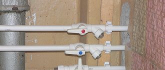
Recently, convenient, safe and lightweight plastic boxes have been produced specifically for intra-apartment use.
Algorithm for calculating air speed
Taking into account the above conditions and technical parameters of a particular room, it is possible to determine the characteristics of the ventilation system, as well as calculate the air velocity in the pipes.
It should be based on the rate of air exchange, which is the determining value for these calculations.
To clarify the flow parameters, the table is useful:
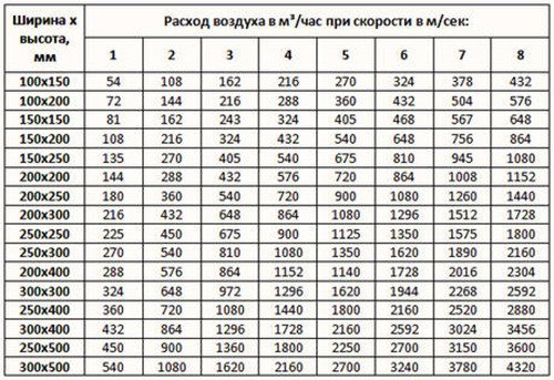
The table shows the dimensions of rectangular air ducts, that is, their length and width are indicated. For example, when using channels 200 mm x 200 mm at a speed of 5 m / s, the air consumption will be 720 m³ / h
To make the calculations yourself, you need to know the volume of the room and the rate of air exchange rate for a room or hall of a given type.
For example, you need to know the parameters for a studio with a kitchen with a total volume of 20 m³. Let's take the minimum multiplicity for the kitchen - 6. It turns out that within 1 hour the air ducts must move about L = 20 m³ * 6 = 120 m³.
You also need to know the cross-sectional area of the air ducts installed in the ventilation system. It is calculated using the following formula:
S = πr2 = π / 4 * D2,
Where:
- S - cross-sectional area of the air duct;
- π - the number "pi", a mathematical constant equal to 3.14;
- r - radius of the duct section;
- D - cross-sectional diameter of the duct.
Suppose that the diameter of a round duct is 400 mm, we substitute it into the formula and we get:
S = (3.14 * 0.4²) / 4 = 0.1256 m²
Knowing the cross-sectional area and flow rate, we can calculate the speed. The formula for calculating the air flow rate:
V = L / 3600 * S,
Where:
- V - air flow speed, (m / s);
- L - air consumption, (m³ / h);
- S - cross-sectional area of air ducts (air ducts), (m2).
Substituting the known values, we get: V = 120 / (3600 * 0.1256) = 0.265 m / s
Therefore, in order to ensure the required air exchange rate (120 m3 / h) when using a round air duct with a diameter of 400 mm, it will be necessary to install equipment that allows the air flow rate to be increased to 0.265 m / s.
It should be remembered that the factors described earlier - the parameters of the vibration level and the noise level - directly depend on the speed of air movement.
If the noise exceeds the norm, it will be necessary to reduce the speed, therefore, to increase the cross-section of the air ducts. In some cases, it is sufficient to install pipes from a different material or replace the curved canal fragment with a straight one.
What device measure the speed of air movement
All devices of this type are compact and easy to use, although there are some subtleties here.
Air velocity measuring instruments:
- Vane anemometers
- Temperature anemometers
- Ultrasonic anemometers
- Pitot tube anemometers
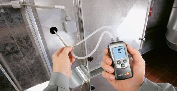
- Differential pressure gauges
- Balometers
Vane anemometers are one of the simplest devices in design. The flow rate is determined by the speed of rotation of the impeller of the device.
Temperature anemometers have a temperature sensor. In a heated state, it is placed in the air duct and, as it cools, the air flow rate is determined.
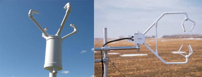
Ultrasonic anemometers mainly measure wind speed. They work on the principle of detecting the difference in sound frequency at selected test points of the air flow.
Pitot tube anemometers are equipped with a special small diameter tube. It is placed in the middle of the duct, thereby measuring the difference in total and static pressure. These are one of the most popular devices for measuring air in the duct, but at the same time they have a drawback - they cannot be used with a high concentration of dust.
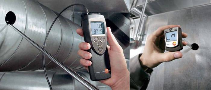
Differential pressure gauges can measure not only speed, but also air flow. Complete with a pitot tube, this device can measure air flows up to 100 m / s.
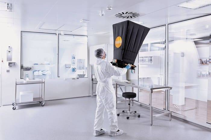
Balometers are most effective in measuring the air velocity at the outlet of ventilation grilles and diffusers. They have a funnel that captures all the air coming out of the ventilation grille, thereby minimizing the measurement error.
Setting up a functioning ventilation system
The main way to diagnose the operation of ventilation networks is to measure the air speed in the duct, since knowing the diameter of the channels it is easy to calculate the real flow rate of air masses. The devices that are used for this are called anemometers. Depending on the characteristics of the movement of air masses, apply:
- Mechanical devices with impeller. Measurement range 0.2 - 5 m / s;
- Cup anemometers measure air flow in the range of 1 - 20 m / s;
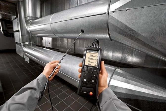
- Electronic hot-wire anemometers can be used for measurements in any ventilation networks.
It is worth dwelling on these devices in more detail. Electronic hot-wire anemometers do not require, as in the use of analog devices, the organization of hatches in the channels. All measurements are made by installing a sensor and receiving data on a screen built into the device. Measurement errors for such devices do not exceed 0.2%. Most modern models can operate both on batteries and on a 220 v power supply. That is why professionals recommend using electronic anemometers for commissioning.
As a conclusion: the speed of movement of air flows, air flow rate and cross-sectional area of the channels are the most important parameters for the design of air distribution and ventilation networks.
Tip: In this article, as an illustrative example, the aerodynamic calculation method for the section of the air duct of the ventilation system was given.Conducting computational operations is a rather complex process that requires knowledge and experience, and also takes into account a lot of nuances. Do not do the calculations yourself, but entrust it to professionals.
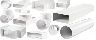
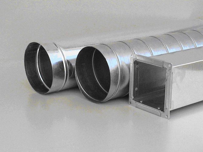
Sectional shapes
According to the cross-sectional shape, pipes for this system are divided into round and rectangular. Round are mainly used in large industrial plants. Since they require a large area of the room. Rectangular sections are well suited for residential buildings, kindergartens, schools and clinics. In terms of noise level, pipes with a circular cross-section are in the first place, since they emit a minimum of noise vibrations. There are slightly more noise vibrations from pipes with a rectangular cross-section.
Pipes of both sections are made most often of steel. For pipes with a circular cross-section, steel is used less hard and elastic, for pipes with a rectangular cross-section - on the contrary, the harder the steel, the stronger the pipe.
In conclusion, I would like to say once again about the attention to the installation of air ducts, to the calculations carried out. Remember, how correctly you do everything, the functioning of the system as a whole will be so desirable. And, of course, we must not forget about safety. The parts for the system should be chosen carefully. The main rule should be remembered: cheap does not mean high quality.
Calculation rules
Noise and vibration are closely related to the speed of air masses in the ventilation duct. After all, the flow that passes through the pipes is capable of creating variable pressure that can exceed normal parameters if the number of turns and bends is greater than optimal values. When the resistance in the ducts is high, the air speed is significantly lower, and the efficiency of the fans is higher.
Many factors affect the vibration threshold, for example - pipe material
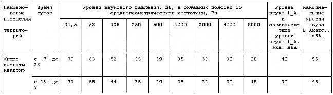
Standard noise level
In SNiP, certain standards are indicated that affect premises of a residential, public or industrial type. All standards are indicated in tables. If the accepted standards are increased, it means that the ventilation system is not designed properly. In addition, exceeding the sound pressure standard is permissible, but only for a short time.
If the maximum permissible values are exceeded, then the channel system was created with any shortcomings, which should be corrected in the near future. The fan power can also influence excessive vibration levels. The maximum air velocity in the duct should not contribute to an increase in noise.
Valuation principles
Various materials are used for the manufacture of ventilation pipes, the most common of which are plastic and metal pipes. The shapes of the air ducts have different sections, ranging from round and rectangular to ellipsoidal. SNiP can only indicate the dimensions of the chimneys, but not standardize the volume of air masses in any way, since the type and purpose of the premises can differ significantly. The prescribed norms are intended for social facilities - schools, preschool institutions, hospitals, etc.
All dimensions are calculated using certain formulas. There are no specific rules for calculating the air speed in ducts, but there are recommended standards for the required calculation, which can be seen in SNiPs. All data is used in the form of tables.
It is possible to supplement the given data in this way: if the hood is natural, then the air velocity should not exceed 2 m / s and be less than 0.2 m / s, otherwise the air flows in the room will be updated badly. If ventilation is forced, then the maximum allowable value is 8-11 m / s for main air ducts. If this standard is higher, the ventilation pressure will be very high, resulting in unacceptable vibration and noise.

Rules for determining the air speed in the duct
With an increase in the diameter of the pipes, the air speed decreases and the pressure drops.
The air flow rate in ventilation is directly related to the level of vibration and noise in the system. These metrics need to be considered when calculating behavior. The movement of the air mass creates noise, the intensity of which depends on the number of pipe bends. Resistance also plays an important role: the higher it is, the lower the speed of movement of air masses will be.
Noise level
On the basis of sanitary standards, the maximum possible sound pressure values are set in the premises.
Exceeding the listed parameters is possible only in exceptional cases, when additional equipment needs to be connected to the system.
Vibration level
The level of noise and vibration depends on the inner surface of the pipe
Vibration is generated during operation of any ventilation device. Its performance depends on the material from which the duct is made.
The maximum vibration depends on several factors:
- the quality of the gaskets that are designed to reduce vibration levels;
- pipe material;
- duct size;
- air flow rate.
General indicators cannot be higher than those established by sanitary standards.
Air exchange rate
Purification of air masses occurs due to air exchange, it is divided into forced and natural. In the second case, it is achieved by opening windows, vents, in the first, through the installation of fans and air conditioners.
For an optimal microclimate, air changes should occur at least once an hour. The number of such cycles is called the air exchange rate. It must be determined in order to establish the speed of air movement in the ventilation duct.
The frequency rate is calculated according to the formula N = V / W, where N is the rate per hour; V is the volume of air that fills a cubic meter of the room per hour; W is the volume of the room in cubic meters.
Basic formulas for aerodynamic calculation
The first step is to make the aerodynamic calculation of the line. Recall that the longest and most loaded section of the system is considered the main duct. Based on the results of these calculations, the fan is selected.
Just do not forget about linking the rest of the branches of the system
It is important! If it is not possible to tie on the branches of the air ducts within 10%, diaphragms should be used. The resistance coefficient of the diaphragm is calculated using the formula:
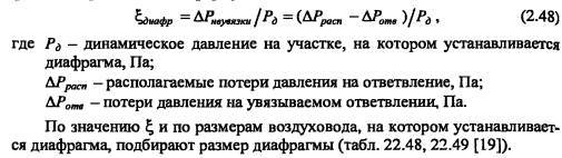
If the discrepancy is more than 10%, when the horizontal duct enters the vertical brick channel, rectangular diaphragms must be placed at the junction.
The main task of the calculation is to find the pressure loss. At the same time, choosing the optimal size of the air ducts and controlling the air speed. The total pressure loss is the sum of two components - the pressure loss along the length of the ducts (by friction) and the loss in local resistances. They are calculated by the formulas
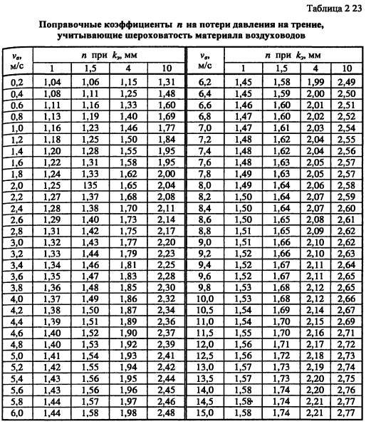
These formulas are correct for steel ducts, for all others a correction factor is entered. It is taken from the table depending on the speed and roughness of the air ducts.
For rectangular air ducts, the equivalent diameter is taken as the calculated value.
Let us consider the sequence of aerodynamic calculation of air ducts using the example of the offices given in the previous article, using the formulas. And then we will show how it looks in Excel.
Calculation example
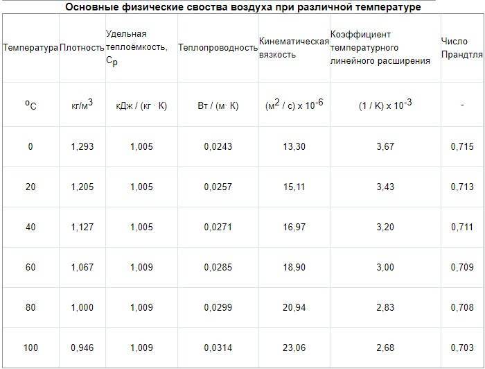
According to calculations in the office, the air exchange is 800 m3 / hour. The task was to design air ducts in offices no more than 200 mm high. The dimensions of the premises are given by the customer. The air is supplied at a temperature of 20 ° C, the air density is 1.2 kg / m3.
It will be easier if the results are entered into a table of this type
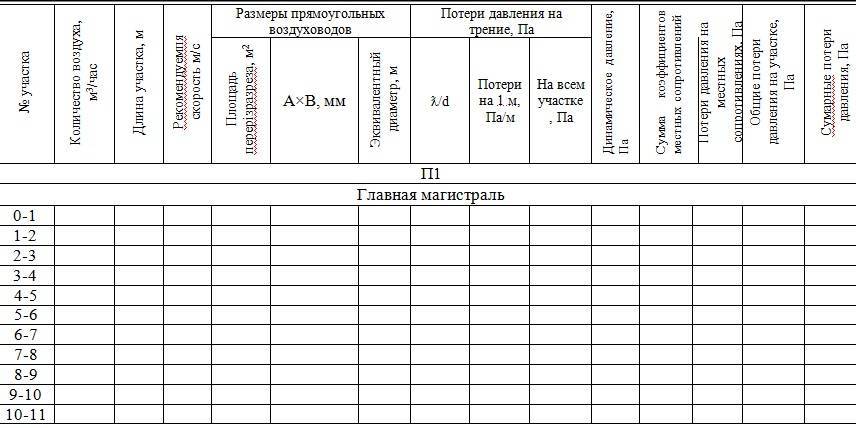
First, we will do an aerodynamic calculation of the main line of the system.Now everything is in order:
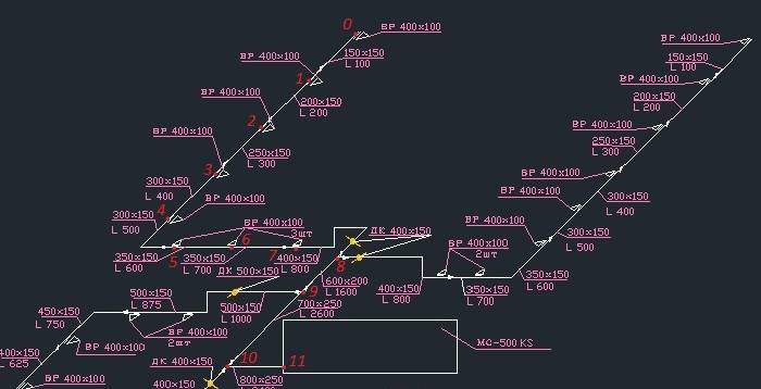
We divide the highway into sections along the supply grilles. We have eight gratings in our room, each with 100 m3 / hour. It turned out 11 sites. We enter the air consumption at each section in the table.
- We write down the length of each section.
- The recommended maximum speed inside the duct for office premises is up to 5 m / s. Therefore, we select such a size of the duct so that the speed increases as we approach the ventilation equipment and does not exceed the maximum. This is to avoid ventilation noise. Let's take for the first section we take an air duct 150x150, and for the last one 800x250.
V1 = L / 3600F = 100 / (3600 * 0.023) = 1.23 m / s.V11 = 3400/3600 * 0.2 = 4.72 m / s
We are satisfied with the result. We determine the dimensions of the ducts and the speed using this formula at each site and enter them into the table.
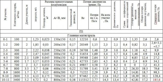
- We start calculating the pressure loss. We determine the equivalent diameter for each section, for example, the first de = 2 * 150 * 150 / (150 + 150) = 150. Then we fill in all the data necessary for the calculation from the reference literature or calculate: Re = 1.23 * 0.150 / (15.11 * 10 ^ -6) = 12210. λ = 0.11 (68/12210 + 0.1 / 0.15) ^ 0.25 = 0.0996 The roughness of different materials is different.
- Dynamic pressure Pd = 1.2 * 1.23 * 1.23 / 2 = 0.9 Pa is also recorded in the column.
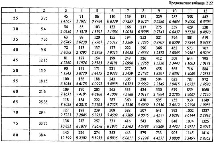
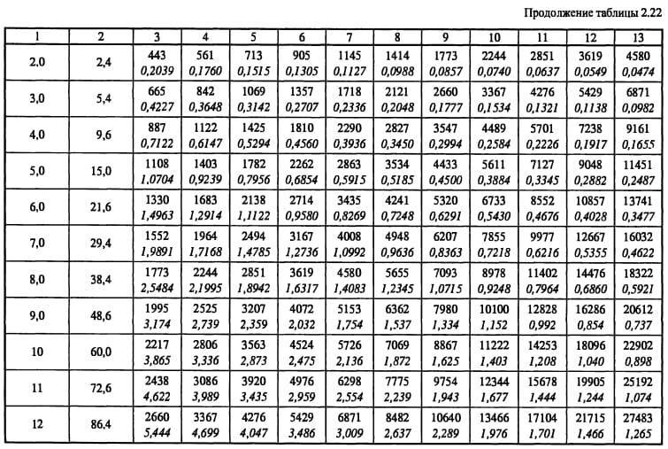
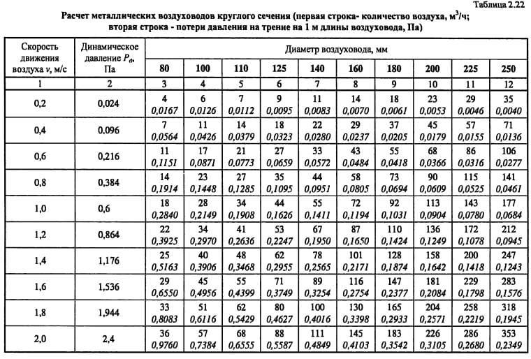
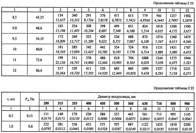
- From table 2.22 we determine the specific pressure loss or calculate R = Pd * λ / d = 0.9 * 0.0996 / 0.15 = 0.6 Pa / m and enter it into a column. Then, at each section, we determine the pressure loss due to friction: ΔРtr = R * l * n = 0.6 * 2 * 1 = 1.2 Pa.
- We take the coefficients of local resistances from the reference literature. In the first section, we have a lattice and an increase in the duct in the sum of their CMC is 1.5.
- Pressure loss in local resistances ΔРm = 1.5 * 0.9 = 1.35 Pa
- We find the sum of the pressure losses in each section = 1.35 + 1.2 = 2.6 Pa. And as a result, the pressure loss in the entire line = 185.6 Pa. the table by that time will look like
Further, the calculation of the remaining branches and their linking is carried out using the same method. But let's talk about this separately.
Parameter values in various types of air ducts
In modern ventilation systems, installations are used that include the entire complex for supplying and processing air: cleaning, heating, cooling, humidifying, sound absorption. These units are called central air conditioners. The flow rate inside it is regulated by the manufacturer. The fact is that all elements for processing air masses must operate in an optimal mode in order to provide the required air parameters. Therefore, manufacturers manufacture enclosures of installations of certain sizes for a given range of air flow rates, at which all equipment will work efficiently. Typically, the value of the flow velocity inside the central air conditioner is in the range of 1.5-3 m / s.
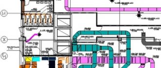
Trunk channels and branches
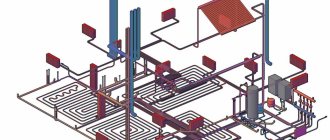
Main air duct diagram.
Next comes the turn of the main main duct. It is often long in length and transits through several rooms before branching out. The recommended maximum speed of 8 m / s in such ducts may not be met, since the installation conditions (especially through ceilings) can significantly limit the space for its installation. For example, at a flow rate of 35,000 m³ / h, which is not uncommon in enterprises, and a speed of 8 m / s, the pipe diameter will be 1.25 m, and if it is increased to 13 m / s, then the size will become 1000 mm. Such an increase is technically feasible, since modern galvanized steel air ducts, made by a spiral-wound method, have high rigidity and density. This eliminates vibration at high speeds. The noise level from such work is quite low, and against the background of the sound from the operating equipment it can be practically inaudible. Table 2 shows some popular diameters of main air ducts and their throughput at different speeds of air masses.
table 2
| Consumption, m3 / h | Ø400 mm | Ø450 mm | Ø500 mm | Ø560 mm | Ø630 mm | Ø710 mm | Ø800 mm | Ø900 mm | Ø1 m |
| ϑ = 8 m / s | 3617 | 4576 | 5650 | 7087 | 8971 | 11393 | 14469 | 18311 | 22608 |
| ϑ = 9 m / s | 4069 | 5148 | 6357 | 7974 | 10093 | 12877 | 16278 | 20600 | 25434 |
| ϑ = 10 m / s | 4521 | 5720 | 7063 | 8859 | 11214 | 14241 | 18086 | 22888 | 28260 |
| ϑ = 11 m / s | 4974 | 6292 | 7769 | 9745 | 12335 | 15666 | 19895 | 25177 | 31086 |
| ϑ = 12 m / s | 5426 | 6864 | 8476 | 10631 | 13457 | 17090 | 21704 | 27466 | 33912 |
| ϑ = 13 m / s | 5878 | 7436 | 9182 | 11517 | 14578 | 18514 | 23512 | 29755 | 36738 |
Diagram of an ejection ventilation system.
The lateral branches of the air ducts distribute the supply or exhaust of the air mixture to separate rooms.As a rule, a diaphragm or a throttle valve is installed on each of them to adjust the amount of air. These elements have considerable local resistance; therefore, it is impractical to maintain a high speed. However, its value can also fall outside the recommended range, therefore Table 3 shows the throughput of the most popular diameters for branches at various speeds.
Table 3
| Consumption, m3 / h | Ø140 mm | Ø160 mm | Ø180 mm | Ø200 mm | Ø225 mm | Ø250 mm | Ø280 mm | Ø315 mm | Ø355 mm |
| ϑ = 4 m / s | 220 | 288 | 366 | 452 | 572 | 705 | 885 | 1120 | 1424 |
| ϑ = 4.5 m / s | 248 | 323 | 411 | 508 | 643 | 793 | 994 | 1260 | 1601 |
| ϑ = 5 m / s | 275 | 360 | 457 | 565 | 714 | 882 | 1107 | 1400 | 1780 |
| ϑ = 5.5 m / s | 302 | 395 | 503 | 621 | 786 | 968 | 1215 | 1540 | 1957 |
| ϑ = 6 m / s | 330 | 432 | 548 | 678 | 857 | 1058 | 1328 | 1680 | 2136 |
| ϑ = 7 m / s | 385 | 504 | 640 | 791 | 1000 | 1235 | 1550 | 1960 | 2492 |
Not far from the point of connection to the main line, a hatch is arranged in the channel; it is needed to measure the flow rate after installation and adjust the entire ventilation system.
Indoor ducts
Ventilation air exchange rate.
Distribution channels connect the main branch to devices for supplying or exhausting air from the room: grilles, distribution or suction panels, diffusers and other distribution elements. The speeds in these branches can be maintained as in the main branch, if the capacity of the ventilation unit allows it, or it can be reduced to the recommended ones. Table 4 shows the air flow rates at different speeds and channel diameters.
Table 4
| Consumption, m3 / h | Ø100 mm | Ø112 mm | Ø125 mm | Ø140 mm | Ø160 mm | Ø180 mm | Ø200 mm | Ø225 mm |
| ϑ = 1.5 m / s | 42,4 | 50,7 | 65,8 | 82,6 | 108 | 137 | 169 | 214 |
| ϑ = 2 m / s | 56,5 | 67,7 | 87,8 | 110 | 144 | 183 | 226 | 286 |
| ϑ = 2.5 m / s | 70,6 | 84,6 | 110 | 137 | 180 | 228 | 282 | 357 |
| ϑ = 3 m / s | 84,8 | 101 | 132 | 165 | 216 | 274 | 339 | 429 |
| ϑ = 3.5 m / s | 99,9 | 118 | 153 | 192 | 251 | 320 | 395 | 500 |
| ϑ = 4 m / s | 113 | 135 | 175 | see Table 3 | ||||
The speeds recommended for exhaust and supply grilles, as well as other air distribution devices, must be observed.
The air at the outlet from them or during suction encounters many small obstacles and produces noise, the level of which is unacceptable. The sound of a stream emerging from the grate at high speed will certainly be heard. Another unpleasant moment: a strong air jet, falling on people, can lead to their diseases.
Naturally induced ventilation systems are usually used in residential and public buildings or in the office buildings of industrial enterprises. These are all sorts of exhaust shafts located in the internal partitions of the premises, or external vertical air ducts. The speed of the air flow in them is low, rarely reaching 2-3 m / s in cases where the shaft has a significant height and good thrust occurs. When it comes to low costs (about 100-200 m³ / h), there is no better solution than natural extraction. Earlier to this day, roof deflectors operated by wind load are used in industrial premises. The air speed in such exhaust devices depends on the strength of the wind flow and reaches 1-1.5 m / s.
Measurement of air flow parameters when setting up the system
After the supply or exhaust ventilation system is installed, it must be adjusted. To do this, using the hatches on the air ducts, the flow rate is measured on all highways and branches of the system, after which they are adjusted with throttle valves or air dampers. It is the air speed in the channels that is the determining parameter during adjustment, through it and the diameter, the flow rate in each of the sections is calculated. The devices that carry out these measurements are called anemometers. There are several types of devices and work on different principles, each type is designed to measure a specific range of speeds.
Types of ventilation in a private house.
- Vane-type anemometers are lightweight, easy to use, but have some measurement error. The principle of operation is mechanical, the range of measured speeds is from 0.2 to 5 m / s.
- Cup-type devices are also mechanical, but the range of tested speeds is wider, from 1 to 20 m / s.
- Hot-wire anemometers take readings not only of the flow rate, but also of its temperature. The principle of operation is electrical, from a special sensor introduced into the air flow, the results are displayed on the screen. The device operates on a 220 V network, it takes less time to measure, and its error is low.There are battery operated devices, the ranges of the tested speeds can be very different, depending on the type of device and the manufacturer.
The value of the air flow velocity, along with two other parameters, the flow rate and the duct cross-section, is one of the most important factors in the operation of ventilation systems for any purpose.
This parameter is present at all stages, from calculating the air speed in the duct and ending with the adjustment of the system after its installation and start-up.
Do I need to focus on SNiP
In all the calculations that we carried out, the recommendations of SNiP and MGSN were used. This regulatory documentation allows you to determine the minimum permissible ventilation performance, which ensures a comfortable stay of people in the room. In other words, SNiP requirements are aimed primarily at minimizing the cost of the ventilation system and the cost of its operation, which is important when designing ventilation systems for administrative and public buildings.
In apartments and cottages, the situation is different, because you are designing ventilation for yourself, and not for the average resident, and no one forces you to adhere to the recommendations of SNiP. For this reason, system performance can be either higher than the design value (for more comfort) or lower (to reduce energy consumption and system cost). In addition, the subjective feeling of comfort is different for everyone: for some, 30–40 m³ / h per person is enough, while for others, 60 m³ / h is not enough.
However, if you do not know what kind of air exchange you need to feel comfortable, it is better to adhere to the SNiP recommendations. Since modern air handling units allow you to adjust the performance from the control panel, you can find a compromise between comfort and economy already during the operation of the ventilation system.
Estimated air exchange
For the calculated value of air exchange, the maximum value is taken from the calculations for heat input, moisture input, intake of harmful vapors and gases, according to sanitary standards, compensation for local hoods and the standard rate of air exchange.
The air exchange of residential and public premises is usually calculated according to the frequency of air exchange or according to sanitary standards.
After calculating the required air exchange, the air balance of the premises is compiled, the number of air diffusers is selected and the aerodynamic calculation of the system is made. Therefore, we advise you not to neglect the calculation of air exchange if you want to create comfortable conditions for your stay in the room.
Why measure air speed
For ventilation and air conditioning systems, one of the most important factors is the condition of the supplied air. That is, its characteristics.
The main parameters of the air flow include:
- air temperature;
- air humidity;
- air flow rate;
- flow rate;
- duct pressure;
- other factors (pollution, dustiness ...).
SNiPs and GOSTs describe normalized indicators for each of the parameters. Depending on the project, the value of these indicators may change within the acceptable limits.
The speed in the duct is not strictly regulated by regulatory documents, but the recommended value of this parameter can be found in the designers' manuals. You can learn how to calculate the speed in the duct and get acquainted with its permissible values by reading this article.
For example, for civil buildings, the recommended air speed along the main ventilation ducts is within 5-6 m / s. Correctly performed aerodynamic calculation will solve the problem of supplying air at the required speed.
But in order to constantly observe this speed regime, it is necessary to control the speed of air movement from time to time.Why? After a while, the air ducts, ventilation channels become dirty, the equipment may malfunction, the air duct connections are depressurized. Also, measurements must be carried out during routine inspections, cleaning, repairs, in general, when servicing ventilation. In addition, the speed of movement of flue gases, etc. is also measured.
Calculation procedure
The calculation algorithm is as follows:
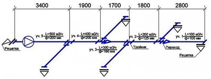
- An axonometric diagram is drawn up listing all the elements.
- Based on the diagram, the length of the channels is calculated.
- The flow rate at each of its sections is determined. Each individual section has a single section of air ducts.
- After that, calculations of the speed of air movement and pressure in each separate section of the system are carried out.
- Next, friction losses are calculated.
- Using the required coefficient, the pressure loss for local resistances is calculated.
In the process of calculations, at each section of the air distribution network, various data will be obtained, which must be equalized with the branch of greatest resistance using diaphragms.
Some helpful tips and notes
As can be understood from the formula (or when carrying out practical calculations on calculators), the air speed increases with decreasing pipe dimensions. Several advantages can be derived from this fact:
- there will be no losses or the need to lay an additional ventilation pipeline to ensure the required air flow, if the dimensions of the room do not allow for large ducts;
- smaller pipelines can be laid, which in most cases is easier and more convenient;
- the smaller the channel diameter, the cheaper its cost, the price of additional elements (dampers, valves) will also decrease;
- the smaller size of the pipes expands the possibilities of installation, they can be positioned as needed, practically without adjusting to external constraining factors.
However, when laying air ducts of a smaller diameter, it must be remembered that with an increase in the air speed, the dynamic pressure on the pipe walls increases, the resistance of the system also increases, and accordingly a more powerful fan and additional costs will be required. Therefore, before installation, it is necessary to carefully carry out all the calculations so that the savings do not turn into high costs or even losses, because a building that does not comply with SNiP standards may not be allowed to operate.
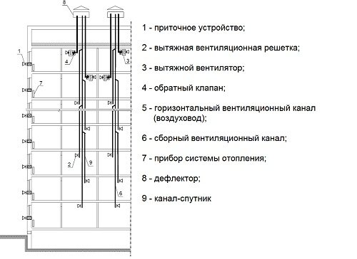
Description of the ventilation system
Air ducts are certain elements of the ventilation system that have different cross-sectional shapes and are made of different materials. To make optimal calculations, it will be necessary to take into account all the dimensions of the individual elements, as well as two additional parameters, such as the volume of air exchange and its speed in the duct section.
Violation of the ventilation system can lead to various diseases of the respiratory system and significantly reduce the resistance of the immune system. Also, excess moisture can lead to the development of pathogenic bacteria and the appearance of fungus. Therefore, when installing ventilation in homes and institutions, the following rules apply:
Each room requires the installation of a ventilation system. It is important to observe air hygiene standards. In places with different functional purposes, different schemes of ventilation system equipment are required.
In this video, we will consider the best combination of hood and ventilation:
This is interesting: calculating the area of air ducts.
The importance of proper air exchange
The main purpose of ventilation is to create and maintain a favorable microclimate inside residential and industrial premises.
If the air exchange with the outside atmosphere is too intense, then the air inside the building will not have time to warm up, especially in the cold season.Accordingly, the premises will be cold and not humid enough.
Conversely, at a low rate of air mass renewal, we get a waterlogged, excessively warm atmosphere, which is harmful to health. In advanced cases, the appearance of fungi and mold on the walls is often observed.
A certain balance of air exchange is needed, which will allow maintaining such indicators of humidity and air temperature, which have a positive effect on human health. This is the most important task that needs to be addressed.
Air exchange depends mainly on the speed of air passing through the ventilation ducts, the cross section of the air ducts themselves, the number of bends in the route and the length of sections with smaller diameters of air pipes.
All these nuances are taken into account when designing and calculating the parameters of the ventilation system.
These calculations allow you to create reliable indoor ventilation that meets all the regulatory indicators approved in the "Building codes and regulations".