Choosing a heater
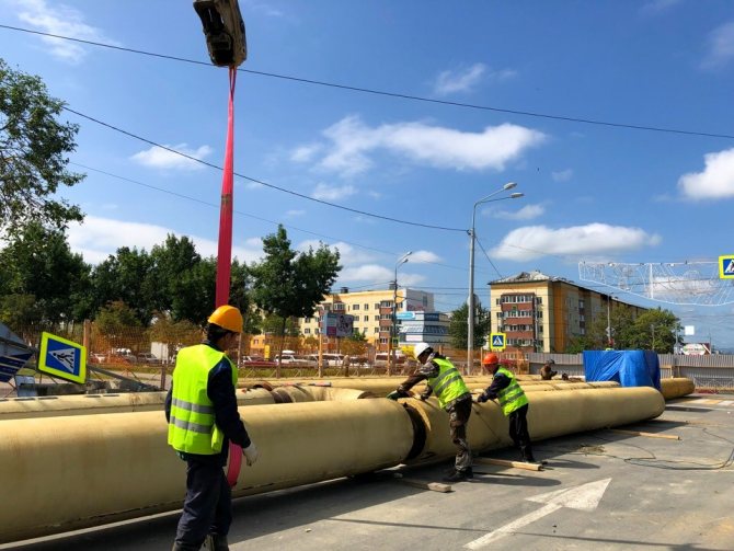
The main reason for pipelines freezing is insufficient circulation rate of the energy carrier. In this case, at sub-zero air temperatures, the process of liquid crystallization may begin. So high-quality pipe insulation is vital.
Fortunately, our generation is incredibly lucky. In the recent past, pipelines were insulated using only one technology, since there was only one insulation - glass wool. Modern manufacturers of heat-insulating materials offer simply the widest selection of heaters for pipes, differing in composition, characteristics and method of application.
It is not entirely correct to compare them with each other, and even more so to claim that one of them is the best. So let's just look at the types of pipe insulation materials.
By scope:
- for pipelines of cold and hot water supply, steam pipelines of central heating systems, various technical equipment;
- for sewerage systems and drainage systems;
- for pipes of ventilation systems and freezing equipment.
In appearance, which, in principle, immediately explains the technology of using heaters:
- roll;
- leafy;
- shroud;
- filling;
- combined (this rather already refers to the method of pipeline insulation).
The main requirements for the materials from which heaters for pipes are made are low thermal conductivity and good fire resistance.
The following materials fit these important criteria:
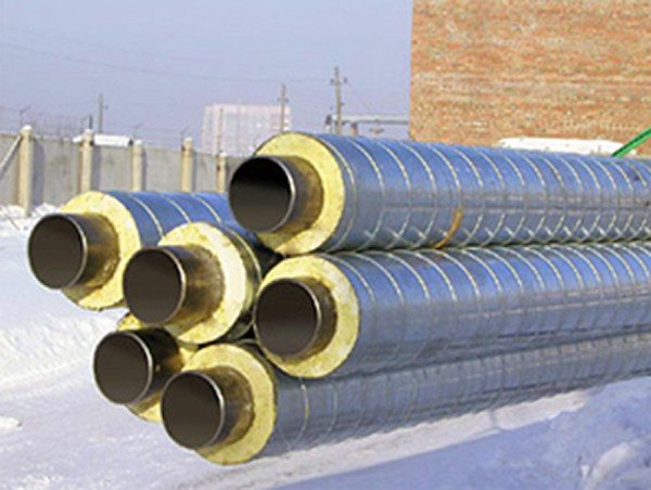
Mineral wool. Most often sold in rolls. Suitable for thermal insulation of pipelines with high temperature heat carrier. However, if you use mineral wool to insulate pipes in large volumes, then this option will not be very profitable from the point of view of savings. Thermal insulation with mineral wool is produced by winding, followed by its fixing with synthetic twine or stainless wire.
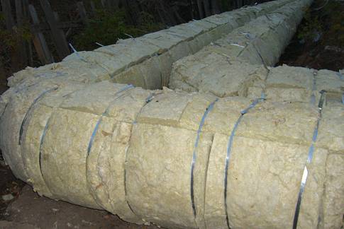
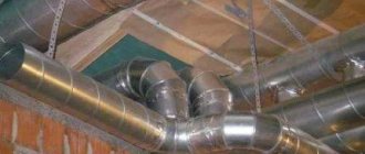
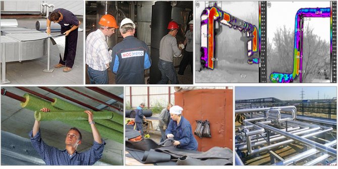
In the photo there is a pipeline insulated with mineral wool
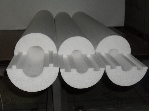
It can be used both at low and high temperatures. Suitable for steel, metal-plastic and other plastic pipes. Another positive feature is that expanded polystyrene has a cylindrical shape, and its inner diameter can be adjusted to the size of any pipe.
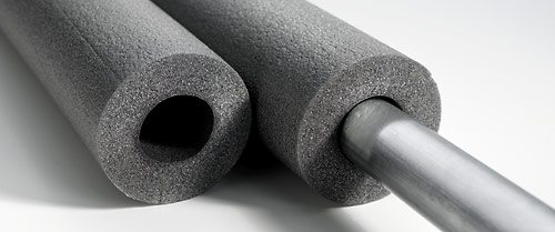
Penoizol. According to its characteristics, it is closely related to the previous material. However, the method of installing penoizol is completely different - a special spray installation is required for its application, since it is a component liquid mixture. After the foam is solidified, an airtight shell forms around the pipe, which almost does not allow heat to pass through. The pluses here also include the lack of additional fastening.
Penoizol in action
Foil penofol. The latest development in the field of insulation materials, but has already won its fans among Russian citizens. Penofol consists of polished aluminum foil and a layer of polyethylene foam.
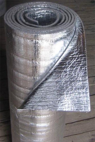
Such a two-layer construction not only retains heat, but even serves as a kind of heater! As you know, foil has heat-reflecting properties, which allows it to accumulate and reflect heat to the insulated surface (in our case, this is a pipeline).
In addition, foil-clad penofol is environmentally friendly, slightly flammable, resistant to temperature extremes and high humidity.
As you can see, there are plenty of materials! There is plenty to choose how to insulate pipes. But when choosing, do not forget to take into account the peculiarities of the environment, the characteristics of the insulation and its ease of installation.Well, it would not hurt to calculate the thermal insulation of pipes in order to do everything correctly and reliably.
Insulation laying
The insulation calculation depends on the type of installation used. It can be outside or inside.
External insulation is recommended for the protection of heating systems. It is applied along the outer diameter, provides protection against heat loss, the appearance of traces of corrosion. To determine the volumes of material, it is sufficient to calculate the surface area of the pipe.
Thermal insulation maintains the temperature in the pipeline regardless of the effect of environmental conditions on it.
Internal laying is used for plumbing.
It perfectly protects against chemical corrosion, prevents heat loss from routes with hot water. Usually it is a coating material in the form of varnishes, special cement-sand mortars. The choice of material can also be carried out depending on which gasket will be used.
Duct laying is in demand most often. For this, special channels are preliminarily arranged, and the tracks are placed in them. Less often, the channelless method of laying is used, since special equipment and experience are required to carry out the work. The method is used in the case when it is not possible to carry out work on the installation of trenches.
Capabilities
Optimal selection of thermal insulation structures and materials
Calculation of the minimum required thickness of the thermal insulation layer (for the case of one or two materials in the thermal insulation layer)
Selection of standard sizes of products
Calculation of the scope of work and the total amount of materials
Release of design documentation
The program calculates insulation for different types of objects:
Onshore and buried pipelines (ducted and non-ducted), including straight sections, bends, transitions, fittings and flange connections;
Two-pipe laying pipelines (channel and channelless), including heating networks;
Various types of equipment - both standard (pumps, tanks, heat exchangers, etc.) and complex composite apparatuses, including various types of shells, bottoms, fittings, hatches and flange connections;
The presence of heating satellites and electrical heating is taken into account.
The initial data for the calculation are: the type and size of the insulated object, its temperature and location; other data are set by default and can be changed by the user. The geometrical dimensions of thermal insulation are calculated depending on the purpose of the insulation, the type of the insulated object, its dimensions, product temperature, environmental parameters, characteristics of the insulation material, taking into account its sealing.
The advantages of calculating and choosing insulation when using the program:
Reducing project execution time;
Improving the accuracy of the selection of insulation, which saves material;
The ability to carry out several calculation options to choose the most efficient one, since time is spent only on entering the initial data.
Thanks to the well-thought-out organization of the user interface and built-in documentation with a methodological description, mastering the program does not require special training and does not take much time.
Insulation installation
Calculation of the amount of insulation largely depends on the method of its application. It depends on the place of application - for the inner or outer insulating layer.
You can do it yourself or use a calculator program to calculate the thermal insulation of pipelines. The outer surface coating is used for hot water pipelines at high temperatures in order to protect it from corrosion. The calculation with this method is reduced to determining the area of the outer surface of the water supply system, to determine the need for a running meter of the pipe.
Internal insulation is used for pipes for water mains. Its main purpose is to protect metal from corrosion. It is used in the form of special varnishes or a cement-sand composition with a layer of several mm thick.
The choice of material depends on the installation method - channel or channelless. In the first case, concrete trays are placed at the bottom of an open trench for placement. The resulting gutters are closed with concrete covers, after which the channel is filled with previously removed soil.
Channelless laying is used when digging a heating main is not possible.
This requires special engineering equipment. Calculating the volume of thermal insulation of pipelines in online calculators is a fairly accurate tool that allows you to calculate the amount of materials without fiddling with complex formulas. Consumption rates of materials are given in the corresponding SNiP.
Posted on: December 29, 2017
(4 ratings, average: 5.00 out of 5) Loading ...
- Date: 15-04-2015Comments: Rating: 26
Correctly performed calculation of the thermal insulation of the pipeline can significantly increase the service life of pipes and reduce their heat loss
However, in order not to be mistaken in the calculations, it is important to take into account even minor nuances.
Thermal insulation of pipelines prevents the formation of condensate, reduces heat exchange between pipes and the environment, and ensures the operability of communications.
Pipeline insulation options
Finally, we will consider three effective methods for thermal insulation of pipelines.
Perhaps some of them will appeal to you:
- Thermal insulation using a heating cable. In addition to traditional isolation methods, there is also such an alternative method. The use of the cable is very convenient and productive, considering that it takes only six months to protect the pipeline from freezing. In the case of heating pipes with a cable, there is a significant saving of effort and money that would have to be spent on earthwork, insulation material and other points. The operating instructions allow for the cable to be located both outside the pipes and inside them.
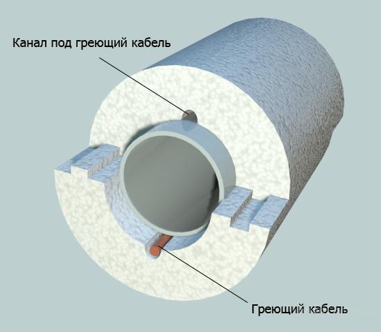
Additional thermal insulation with heating cable
- Warming with air. The mistake of modern thermal insulation systems is this: it is often not taken into account that soil freezing occurs according to the principle "from top to bottom". The heat flux emanating from the depths of the earth tends to meet the freezing process. But since the insulation is carried out on all sides of the pipeline, it turns out that I also isolate it from the rising heat. Therefore, it is more rational to mount a heater in the form of an umbrella over the pipes. In this case, the air gap will be a kind of heat accumulator.
- "A pipe in a pipe". Here, more pipes are laid in polypropylene pipes. What are the advantages of this method? First of all, the pluses include the fact that the pipeline can be warmed up in any case. In addition, heating is possible with a warm air suction device. And in emergency situations, you can quickly stretch the emergency hose, thereby preventing all negative moments.
Pipe-in-pipe insulation
Calculation of the volume of pipeline insulation and laying of material
- Types of insulating materials Laying of insulation Calculation of insulating materials for pipelines Elimination of defects in insulation
Insulation of pipelines is necessary in order to significantly reduce heat loss.
First, you need to calculate the volume of pipe insulation. This will allow not only to optimize costs, but also to ensure the competent performance of work, maintaining the pipes in proper condition. Correctly selected material prevents corrosion and improves thermal insulation.
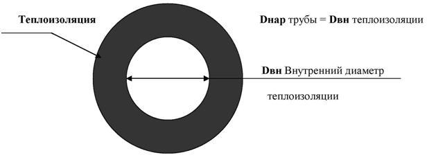
Pipe insulation diagram.
Today, different types of coatings can be used to protect tracks. But it is necessary to take into account exactly how and where the communications will take place.
For water pipes, you can use two types of protection at once - internal coating and external. It is recommended to use mineral wool or glass wool for heating routes, and PPU for industrial ones. Calculations are performed by different methods, it all depends on the selected type of coverage.
Characteristics of network laying and normative calculation methodology
Performing calculations to determine the thickness of the heat-insulating layer of cylindrical surfaces is a rather laborious and complex process
If you are not ready to entrust it to specialists, you should stock up on attention and patience to get the right result. The most common way to calculate pipe insulation is to calculate it using standardized heat loss indicators.
The fact is that SNiPom established the values of heat loss by pipelines of different diameters and with different methods of their laying:
Pipe insulation scheme.
- in an open way on the street;
- open in a room or tunnel;
- channelless method;
- in impassable channels.
The essence of the calculation is in the selection of heat-insulating material and its thickness in such a way that the value of heat losses does not exceed the values prescribed in SNiP. The calculation technique is also regulated by regulatory documents, namely, by the corresponding Code of Rules. The latter offers a slightly more simplified methodology than most of the existing technical reference books. Simplifications are contained in the following points:
Heat losses during heating of the pipe walls by the medium transported in it are negligible in comparison with the losses that are lost in the outer insulation layer. For this reason, they are allowed to be ignored. The vast majority of all process and network piping is made of steel, its resistance to heat transfer is extremely low. Especially when compared with the same indicator of insulation
Therefore, it is recommended not to take into account the resistance to heat transfer of the metal wall of the pipe.
news
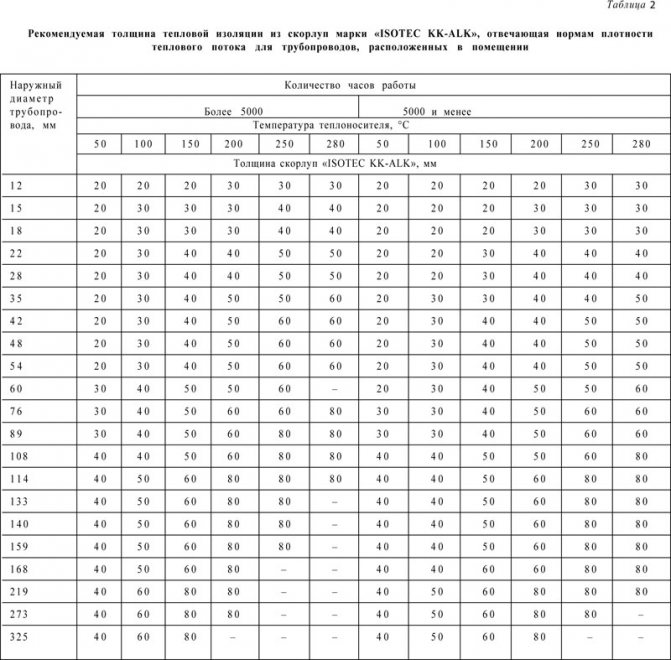
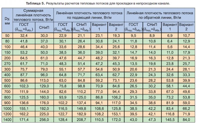
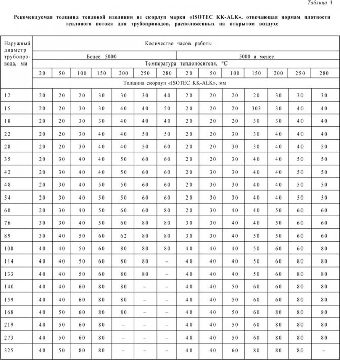
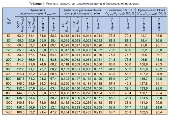
The purpose of the thermal insulation structure determines the thickness of the thermal insulation. The most common is thermal insulation in order to maintain a given heat flux density. The heat flux density can be set based on the conditions of the technological process, or determined according to the standards given in SNiP 41-03-2003 or other regulatory documents. For facilities located in the Sverdlovsk region and Yekaterinburg, the standard value of the heat flux density can be taken according to TSN 23-337-2002 of the Sverdlovsk region. For facilities located on the territory of the Yamalo-Nenets Autonomous Okrug, the standard value of the heat flow density can be taken according to TSN 41-309-2004 of the Yamalo-Nenets Autonomous Okrug. In some cases, the heat flux can be specified based on the total heat balance of the entire object, then it is necessary to determine the total allowable losses. The initial data for the calculation are: a) the location of the insulated object and the ambient air temperature; b) coolant temperature; c) the geometric dimensions of the insulated object; d) the estimated heat flux (heat losses) depending on the number of hours of operation of the facility. The thickness of thermal insulation from shells of the ISOTEC KK-ALK brand, calculated according to the norms of heat flux density for the European region of Russia, for pipelines located outdoors and indoors, is given in Table. 1 and 2 respectively.
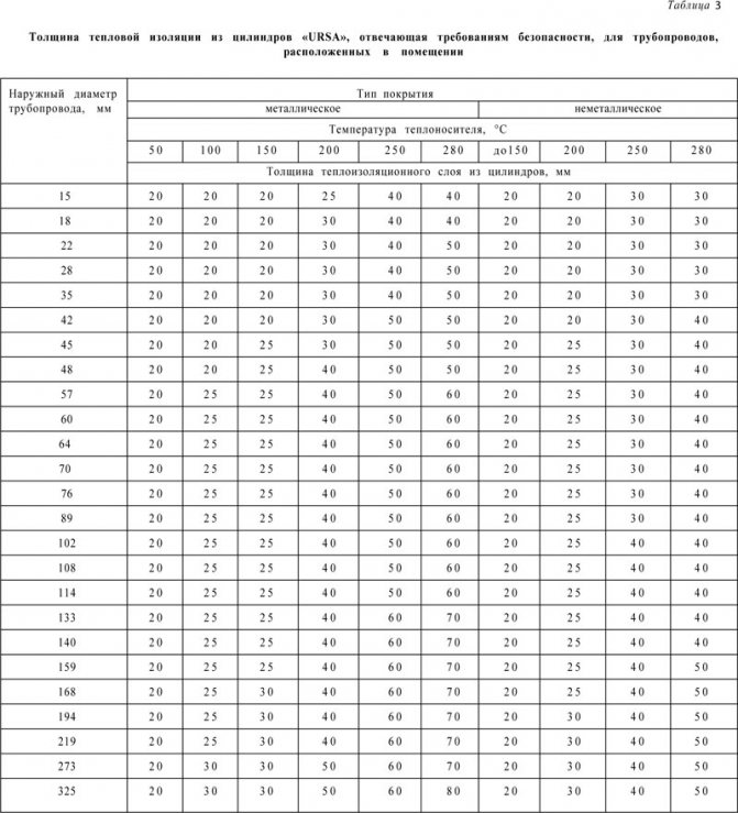
If the heat flux from the surface of the insulation is not regulated, then thermal insulation is necessary as a means of ensuring normal air temperature in the working rooms, or protecting the maintenance personnel from burns. The initial data for calculating the thickness of the heat-insulating layer are: - the location of the insulated object and the ambient air temperature; - coolant temperature; - geometric dimensions of the insulated object; - the required temperature on the surface of the insulation.As a rule, the temperature on the surface of the insulation is taken: - 45 ° С - indoors; - 60 ° С - outdoors with a plaster or non-metallic cover layer; - 50-55 ° C - with a metal cover layer. The thickness of thermal insulation, calculated according to the norms of heat flux density, significantly differs from the thickness of thermal insulation, made in order to protect personnel from burns. Table 3 shows the thickness of thermal insulation for URSA cylinders that meets the requirements for safe operation (set temperature on the surface of the insulation).
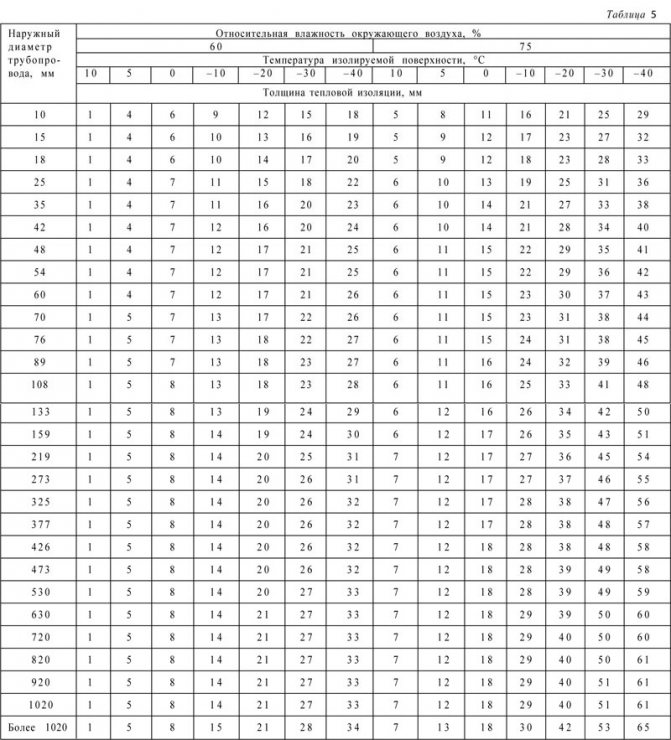
Thermal insulation of equipment and pipelines with negative coolant temperatures can be performed: - in accordance with technological requirements; - in order to prevent or limit the evaporation of the coolant, prevent condensation on the surface of an insulated object located in the room, and prevent the temperature of the coolant from rising not higher than the specified value; - according to the norms of heat flux density (cold loss). Most often, for pipelines with a temperature below ambient air located in a room, insulation is performed in order to prevent moisture condensation on the surface of the thermal insulation structure. The value of the thickness of the thermal insulation layer in this case is influenced by the relative humidity of the ambient air (f), the air temperature in the room (to) and the type of protective coating. Thermal insulation must provide a temperature on the surface of the insulation (tc) above the dew point at the temperature and relative humidity of the ambient air (Φ) in the room. The permissible difference between the temperature of the surface of the insulation and the temperature of the ambient air (to - tc) is given in table. four.
The effect of relative humidity on the thickness of thermal insulation is illustrated in table. 5, which shows the calculated thickness of foam rubber insulation of the K-Flex EC brand without a cover layer at an ambient humidity of 60 and 75%.
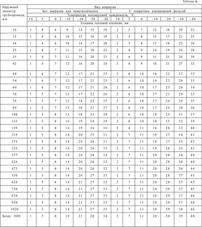
The thickness of the heat-insulating layer to prevent condensation of moisture from the air on the surface of the heat-insulating structure is influenced by the type of coating. When using a coating with a high emissivity (non-metallic), the calculated insulation thickness is lower. Table 6 shows the calculated thickness of foam rubber insulation for pipelines located in a room with a relative humidity of 60%, in an uncoated structure and coated with aluminum foil.
Thermal insulation of cold water pipelines can be performed in order to prevent: - moisture condensation on the surface of the pipeline located in the room; - freezing of water when its movement stops in a pipeline located in the open air. As a rule, this is important for small-diameter pipelines with a small amount of stored heat. The initial data for calculating the thickness of the heat-insulating layer to prevent freezing of water when its movement stops are: a) ambient air temperature; b) the temperature of the substance before stopping its movement; c) inner and outer diameters of the pipeline; d) the maximum possible duration of a break in the movement of a substance; e) material of the pipeline wall (its density and specific heat capacity); f) thermophysical parameters of the transported substance (density, specific heat capacity, freezing temperature, latent heat of freezing). The larger the pipe diameter and the higher the temperature of the liquid, the less likely it is to freeze. As an example, in table. 7 shows the time until the beginning of water freezing in cold water supply pipelines with a temperature of +5 ° С, insulated with ISOTEC KK-ALK shells (in accordance with their nomenclature) at an outdoor air temperature of –20 and –30 ° С.
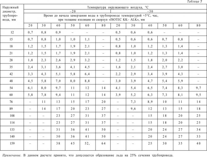
If the ambient temperature is below the specified, then the water in the pipeline will freeze faster.The higher the wind speed and the lower the temperature of the liquid (cold water) and the surrounding air, the smaller the diameter of the pipeline, the more likely the liquid will freeze. The use of insulated non-metallic pipelines reduces the likelihood of cold water freezing.
Back to section
Thermal calculation of the heating network
For the thermal calculation, we will accept the following data:
· Water temperature in the supply pipeline 85 ° C;
· Water temperature in the return pipeline 65 ° C;
· The average air temperature for the heating period of the Republic of Moldova is +0.6 oC;
Let's calculate the losses of uninsulated pipelines. An approximate determination of heat losses per 1 m of an uninsulated pipeline, depending on the temperature difference between the pipeline wall and the ambient air, can be made according to the nomogram. The heat loss value determined from the nomogram is multiplied by the correction factors:
Where: a
- a correction factor that takes into account the temperature difference,
but
=0,91;
b
- correction for radiation, for
d
= 45 mm and
d
= 76 mm
b
= 1.07, and for
d
= 133 mm
b
=1,08;
l
- pipeline length, m.
Heat losses of 1 m of uninsulated pipeline, determined from the nomogram:
for d
= 133 mm
Qnom
= 500 W / m; for
d
= 76 mm
Qnom
= 350 W / m; for
d
= 45 mm
Qnom
= 250 W / m.
Given that the heat loss will be both on the supply and on the return pipelines, the heat loss must be multiplied by 2:
kW.
Heat loss of suspension supports, etc. 10% is added to the heat loss of the uninsulated pipeline itself.
kW.
Standard values of average annual heat losses for a heating network during above-ground laying are determined by the following formulas:
where:, - standard average annual heat losses, respectively, of the supply and return pipelines of the above-ground laying sections, W;
, - standard values of specific heat losses of two-pipe water heating networks, respectively, of the supply and return pipelines for each diameter of pipes for above-ground laying, W / m, determined by;
l
- length of a section of a heating network, characterized by the same diameter of pipelines and type of laying, m;
- coefficient of local heat losses, taking into account heat losses of fittings, supports and compensators. The value of the coefficient in accordance with is taken for an overground installation of 1.25.
Calculation of heat loss of insulated water pipelines is summarized in Table 3.4.
Table 3.4 - Calculation of heat loss of insulated water pipelines
| dн, mm | , W / m | , W / m | l, m | , W | , W |
| 133 | 59 | 49 | 92 | 6,79 | 5,64 |
| 76 | 41 | 32 | 326 | 16,71 | 13,04 |
| 49 | 32 | 23 | 101 | 4,04 | 2,9 |
The average annual heat loss of an insulated heating network will be 49.12 kW / an.
To assess the effectiveness of an insulating structure, an indicator is often used, called the coefficient of insulation efficiency:
Where Qr
, Qand
- heat losses of uninsulated and insulated pipes, W.
Insulation efficiency ratio:
Calculation of the thickness of thermal insulation of pipelines
The purpose of the thermal insulation structure determines the thickness of the thermal insulation. The most common is thermal insulation in order to maintain a given heat flux density. The heat flux density can be set based on the conditions of the technological process, or determined according to the standards given in SNiP 41-03-2003 or other regulatory documents.

For facilities located in the Sverdlovsk region and Yekaterinburg, the standard value of the heat flux density can be taken according to TSN 23-337-2002 of the Sverdlovsk region. For facilities located on the territory of the Yamalo-Nenets Autonomous Okrug, the standard value of the heat flow density can be taken according to TSN 41-309-2004 of the Yamalo-Nenets Autonomous Okrug. In some cases, the heat flux can be specified based on the total heat balance of the entire object, then it is necessary to determine the total allowable losses.
The initial data for the calculation are: a) the location of the insulated object and the ambient air temperature; b) coolant temperature; c) the geometric dimensions of the insulated object; d) the estimated heat flux (heat losses) depending on the number of hours of operation of the facility. The thickness of thermal insulation from shells of the ISOTEC KK-ALK brand, calculated according to the norms of heat flux density for the European region of Russia, for pipelines located outdoors and indoors, is given in Table. 1 and 2 respectively.
If the heat flux from the surface of the insulation is not regulated, then thermal insulation is necessary as a means of ensuring normal air temperature in the working rooms, or protecting the maintenance personnel from burns. The initial data for calculating the thickness of the heat-insulating layer are: - the location of the insulated object and the ambient air temperature; - coolant temperature; - geometric dimensions of the insulated object; - the required temperature on the surface of the insulation.
As a rule, the temperature on the surface of the insulation is taken: - 45 ° С - indoors; - 60 ° С - outdoors with a plaster or non-metallic cover layer; - 50-55 ° С - with a metal cover layer. The thickness of thermal insulation, calculated according to the norms of heat flux density, significantly differs from the thickness of thermal insulation made in order to protect personnel from burns. 3 shows the thickness of thermal insulation for URSA cylinders that meets the requirements for safe operation (set temperature on the surface of the insulation).
Thermal insulation of equipment and pipelines with negative coolant temperatures can be performed: - in accordance with technological requirements; - in order to prevent or limit the evaporation of the coolant, prevent condensation on the surface of an insulated object located in the room, and prevent the temperature of the coolant from rising not higher than the specified value; - according to the norms of heat flux density (cold loss). Most often, for pipelines with a temperature below ambient air located in a room, insulation is performed in order to prevent moisture condensation on the surface of the thermal insulation structure.
The thickness of the thermal insulation layer in this case is influenced by the relative humidity of the ambient air (f), the air temperature in the room (to) and the type of protective coating. The thermal insulation must ensure a temperature on the surface of the insulation (tc) above the dew point at the temperature and relative humidity of the ambient air. (Φ) indoors. The permissible difference between the temperature of the surface of the insulation and the temperature of the ambient air (to - tc) is given in table. four.
The effect of relative humidity on the thickness of thermal insulation is illustrated in table. 5, which shows the calculated thickness of foam rubber insulation of the K-Flex EC brand without a cover layer at an ambient humidity of 60 and 75%.
The thickness of the heat-insulating layer to prevent condensation of moisture from the air on the surface of the heat-insulating structure is influenced by the type of coating.
When using a coating with a high emissivity (non-metallic), the calculated insulation thickness is lower. Table 6 shows the calculated thickness of foam rubber insulation for pipelines located in a room with a relative humidity of 60%, in an uncoated structure and coated with aluminum foil.
Thermal insulation of cold water pipelines can be performed in order to prevent: - moisture condensation on the surface of the pipeline located in the room; - freezing of water when its movement stops in a pipeline located in the open air. As a rule, this is important for small-diameter pipelines with a small amount of stored heat.
The initial data for calculating the thickness of the heat-insulating layer to prevent freezing of water when its movement stops are: a) ambient air temperature; b) the temperature of the substance before stopping its movement; c) inner and outer diameters of the pipeline; d) the maximum possible duration of a break in the movement of a substance; e) material of the pipeline wall (its density and specific heat capacity); f) thermophysical parameters of the transported substance (density, specific heat, freezing temperature, latent heat of freezing). The larger the diameter of the pipeline and the higher the temperature of the liquid, the less likely it is to freeze. As an example, in table. 7 shows the time until the beginning of water freezing in cold water supply pipelines with a temperature of +5 ° С, insulated with ISOTEC KK-ALK shells (in accordance with their nomenclature) at an outdoor air temperature of –20 and –30 ° С.
If the ambient temperature is below the specified, then the water in the pipeline will freeze faster. The higher the wind speed and the lower the temperature of the liquid (cold water) and the surrounding air, the smaller the diameter of the pipeline, the more likely the liquid will freeze. The use of insulated non-metallic pipelines reduces the likelihood of cold water freezing.
Back to section
In the structures of thermal insulation of equipment and pipelines with the temperature of the substances contained in them in the range from 20 to 300 ° С
for all laying methods, except for channelless, should be used
heat-insulating materials and products with a density of not more than 200 kg / m3
and the coefficient of thermal conductivity in a dry state no more than 0.06
For the heat-insulating layer of pipelines with channelless
the gasket should use materials with a density not exceeding 400 kg / m3 and a thermal conductivity coefficient not exceeding 0.07 W / (m · K).
The calculation of the thickness of the thermal insulation of pipelines δk, m according to the normalized density of the heat flux, is performed according to the formula:
where is the outer diameter of the pipeline, m;
the ratio of the outer diameter of the insulating layer to the diameter of the pipeline.
The value is determined by the formula:
base of the natural logarithm;

thermal conductivity of the heat-insulating layer W / (m · oС) determined according to Appendix 14.
Rk is the thermal resistance of the insulation layer, m ° C / W, the value of which is determined during underground duct laying of the pipeline according to the formula:
where is the total thermal resistance of the insulation layer and other additional thermal resistances on the way of thermal
flow, m ° C / W determined by the formula:
where the average temperature of the coolant over the period of operation, oC. In accordance with [6], it should be taken at various temperature conditions according to table 6:
Table 6 - Temperature of the coolant at various modes

Temperature conditions of water heating networks, oC 95-70 150-70 180-70 Pipeline Design temperature of the heat carrier, oC Supply Return
average annual ground temperature for different cities is indicated in [9, c 360]
normalized linear heat flux density, W / m (adopted in accordance with Appendix 15);
coefficient taken according to Appendix 16;
coefficient of mutual influence of temperature fields of adjacent pipelines;
thermal resistance of the surface of the heat-insulating layer, m oС / W, determined by the formula:
where the coefficient of heat transfer from the surface of thermal insulation in
ambient air, W / (m · ° С) which, according to [6], is taken when laying in channels, W / (m · ° С);
d is the outer diameter of the pipeline, m;
thermal resistance of the inner surface of the channel, m oС / W, determined by the formula:
where the heat transfer coefficient from air to the inner surface of the channel, αe = 8 W / (m (the dimensions of the channels are given in Appendix 17) the internal section of the channel, m2; thermal resistance of the channel wall, m oС / W determined by the formula: where is the thermal conductivity of the channel wall, for reinforced concrete is the external equivalent channel diameter, determined by the external dimensions of the channel, m; thermal resistance of the soil , m · oС / W determined by the formula: where is the coefficient of thermal conductivity of the soil, depending on its structure and humidity.
In the absence of data, the value can be taken for wet soils 2.0–2.5 W / (m · ° C), for dry soils 1.0–1.5 W / (m · ° C); land, m The calculated thickness of the heat-insulating layer in the structures of thermal insulation based on fibrous materials and products (mats, plates, canvases) should be rounded to values that are multiples of 10 mm. In structures based on mineral wool half-cylinders, rigid cellular materials, materials made of foamed synthetic rubber, polyethylene foam and foamed plastics, the closest to the design thickness of the products should be taken according to the normative documents for the corresponding materials. If the design thickness of the thermal insulation layer does not coincide with the nomenclature thickness of the selected material, it should nomenclature the nearest higher thickness of the thermal insulation material. It is allowed to take the nearest lower thickness of the heat-insulating layer in cases of calculation based on the temperature on the surface of the insulation and the norms of the heat flux density, if the difference between the calculated and nomenclature thickness does not exceed 3 mm.
EXAMPLE 8 Determine the thickness of thermal insulation according to the normalized heat flux density for a two-pipe heating network with dн = 325 mm, laid in a channel of the KL 120 × 60 type. The depth of the channel is hк = 0.8 m,
The average annual temperature of the soil at the depth of the pipeline axis is tgr = 5.5 oC, the thermal conductivity of the soil λgr = 2.0 W / (m · oC), thermal insulation - thermal insulation mats made of mineral wool on a synthetic binder. The temperature regime of the heating network is 150-70oC.
Decision:
1. According to the formula (51), we determine the inner and outer equivalent diameter of the channel by the inner and outer dimensions of its cross-section:
2. Let us determine by the formula (50) the thermal resistance of the inner surface of the channel
3. Using the formula (52), we calculate the thermal resistance of the channel wall:
4. Using the formula (49), we determine the thermal resistance of the soil:
5. Taking the temperature of the surface of the thermal insulation, (appendix), we determine the average temperatures of the thermal insulation layers of the supply and return pipelines:
6. Using the application, we will also determine the thermal conductivity coefficients of thermal insulation (thermal insulation mats made of mineral wool on a synthetic binder):
7. Using the formula (49), we determine the thermal resistance of the surface of the heat-insulating layer
8. Using the formula (48), we determine the total thermal resistance for the supply and return pipelines:
9. Let us determine the coefficients of mutual influence of the temperature fields of the supply and return pipelines:
10. Determine the required thermal resistance of the layers for the supply and return pipelines according to the formula (47):
x
x = 1.192
x
x = 1.368
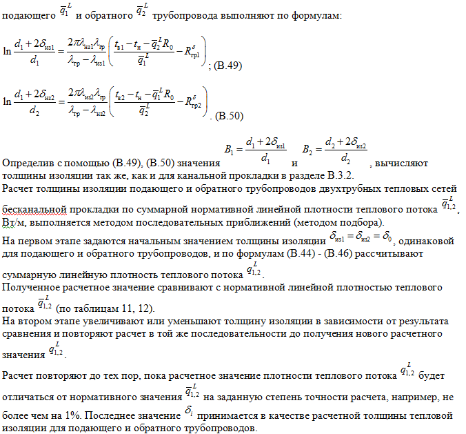
11. The value of B for the supply and return pipelines is determined by the formula (46):
12. Determine the thickness of thermal insulation for the supply and return pipelines using the formula (45):
13.
We accept the thickness of the main layer of insulation for the supply and return pipelines to be the same and equal to 100 mm. References Main 1. Khrustalev, B.M. Heat supply and ventilation: textbook. allowance / B.M. Khrustalev, Yu. Kuvshinov, V.M. Copco.
- M .: Association of building universities, 2008. - 784 p. Additional 2. SNiP 2.04.01-85 *.
Internal water supply and sewerage of buildings. 3. SP 41-101-95. Design of heat points. 4. SNiP 23-01-99 *. Construction climatology. 5. SP 41-103-2000.
Design of thermal insulation of equipment and pipelines. 6. SNiP 41-02-2003. Heating networks. 7. SNiP 41-03-2003. Thermal insulation of equipment and pipelines. 8. Madorskiy, B.M. Operation of central heating points, heating and hot water supply systems / B.M. Madorsky, V.A. Schmidt.
- M .: Stroyizdat, 1971. - 168 p. 9. Adjustment and operation of water heating networks / VI Manyuk [and others]. - M .: Stroyizdat, 1988.
- 432 p. 10 Water heating networks / I.V. Belyaikin [and others]. - M.: Energoatomizdat, 1988 .-- 376 p. 11.
Sokolov, E.Ya. Heating and heating networks: a textbook for universities / E. Ya. Sokolov.– M .: MPEI, 2001.
- 472 p. 12 Tikhomirov, A.K. Heat supply of the city district: textbook. allowance / A.K. Tikhomirov. - Khabarovsk: Pacific Publishing House.
state University, 2006. - 135 pp. TASKS AND METHODOLOGICAL INSTRUCTIONS FOR THE PERFORMANCE OF THE COURSE PROJECT ON THE DISCIPLINE "HEAT SUPPLY OF INDUSTRIAL ENTERPRISES AND CITIES" (GOS - 2000) Signed for printing Format 60´84 / 16.
devices. Flat printing. print
L. Uch.-ed. l. Circulation Order FGAOU VPO "Russian State Professional Pedagogical University", Yekaterinburg, st.
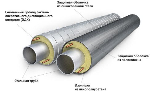
Mashinostroiteley, 11.Risograph FGAOU VPO RGPPU. Yekaterinburg, st. Mashinostroiteley, 11. In the structures of thermal insulation of equipment and pipelines with a temperature of the substances contained in them in the range from 20 ° C to 300 ° C For all laying methods, except channelless, thermal insulation materials and products with a density of not more than 200 kg / m3 and a dry heat conductivity coefficient of not more than 0.06 W / (m K). For the heat-insulating layer of pipelines with channelless laying, materials with a density of not more than 400 kg / m3 and a thermal conductivity coefficient of not more than 0.07 W / (m in a polyethylene sheath or reinforced foam concrete, taking into account the permissible temperature of application of the materials and the temperature schedule for the operation of heating networks.
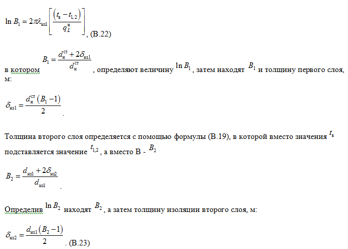
Pipelines with insulation made of polyurethane foam in a polyethylene sheath must be provided with a system for remote control of the insulation moisture. (); The value is determined by the formula:, (2.66) where e is the base of the natural logarithm; k is the thermal conductivity coefficient of the heat-insulating layer, W / (m ° С / W, the value of which is determined from the following expression, (2.67) where is the total thermal resistance of the insulation layer and other additional thermal resistances on the heat flow path determined by the formula (2.68) where is the normalized linear heat flux density, W / m, taken according to [4], and also according to Appendix 8 of the educational manual; - the average temperature of the coolant for the period of operation, - the coefficient taken according to Appendix 11 benefits; - the average annual temperature of the environment; For underground laying - the average annual temperature of the soil, which for most cities is in the range from +1 to +5. When laying in tunnels, in rooms, unheated technical sub-fields, above-ground laying in the open air - the average temperature of the ambient air for the period of operation , which is taken: when laying in tunnels = 40; when laying indoors = 20; unheated technical fields = 5; when laying above ground in open air - the average ambient temperature for the period of operation; Types of additional thermal resistances depend on the method of laying heating networks. tunnels and technical undergrounds (2.69) For underground duct laying (2.70) For underground channelless laying (2.71) where is the thermal resistance of the surface of the insulating layer, m ° C / W, determined by the formula, (2.72) where is the coefficient of heat transfer from the surface of thermal insulation to the ambient air, W / (m2 ° С ) which, according to [4], is taken: when laying in channels = 8 W / (m2 · ° С); when laying in technical undergrounds, closed rooms and in the open air according to table.
2.1; d is the outer diameter of the pipeline, m; Table 2.1 Values of the heat transfer coefficient a, W / (m2 × ° С) Insulated object Indoors Outdoor at wind speed3, m / s Low emissivity coatings1 High emissivity coatings 251015 Horizontal pipelines 7102026351 galvanized steel, sheets of aluminum alloys and aluminum with an oxide film. 2 These include plasters, asbestos-cement coatings, fiberglass, various colors (except paint with aluminum powder). 3 In the absence of information about the wind speed, values corresponding to a speed of 10 m / s. thermal resistance of the channel surface, determined by the formula, (2.73) where is the coefficient of heat transfer from air to the inner surface of the channel; = 8 W / (m2 · ° С); is the internal equivalent channel diameter, m, determined by the formula, (2.74) where F is the internal section channel, m2; P- perimeter of sides by internal dimensions, m; - thermal resistance of the channel wall is determined according to the formula, (2.75) where is the thermal conductivity of the channel wall; for reinforced concrete = 2.04 W / (m ° С); - external equivalent diameter of the channel, determined by the external dimensions of the channel, m; - thermal resistance of the soil determined by the formula, (2.76) where is the thermal conductivity of the soil, depending on its structure and moisture. In the absence of data, its value can be taken for wet soils = 2-2.5 W / (m ° C), for dry soils = 1.0-1.5 W / (m ° C); h is the depth of the axis of the heat pipe from the surface of the earth, m ; - additional thermal resistance, taking into account the mutual influence of pipes during channelless laying, the value of which is determined by the formulas: for the supply pipeline; (2.77) for the return pipeline, (2.78) where h is the depth of the pipeline axes, m; b is the distance between the pipeline axes, m, taken as a function of their nominal bore diameters according to table. 2.2 Table 2.2 Distance between the pipelines axes dy, mm 50-80 100 125-150 200 250 300 350 400 450 500 600 700b, mm 350 400 500 550 600 650 700 600 900 1000 1300 1400, are the coefficients that take into account the mutual influence of the temperature fields of adjacent heat pipelines, determined by the formulas: , W / m (see.
(2.68)) The design thickness of the thermal insulation layer in thermal insulation structures based on fibrous materials and products (mats, plates, canvas) should be rounded to values that are multiples of 10 mm. Structures based on mineral wool cylinders, rigid cellular materials, foamed synthetic rubber, polyethylene foam and foamed plastics if the calculated thickness of the heat-insulating layer does not coincide with the nomenclature thickness of the selected material, the nearest higher thickness of the heat-insulating material should be taken according to the current nomenclature. with a different thickness does not exceed 3 mm. The minimum thickness of the heat-insulating layer should be taken: when insulating with fibrous cylinders materials - equal to the minimum thickness stipulated by state standards or technical conditions; when insulating with fabrics, fiberglass cloth, cords - 20 mm. for insulation with products made of fibrous sealing materials - 20 mm; for insulation with rigid materials, products made of foamed polymers - equal to the minimum thickness stipulated by state standards or specifications. The maximum thickness of the heat-insulating layer in the structures of thermal insulation of equipment and pipelines is given in Table 2.3. ,mmSposob gasket truboprovodaNadzemnyyV tunnel through passage kanalePredelnaya thickness of the insulating layer, mm, at a temperature, ° C 20 and bolee20 and boleedo 150 vkl.3214010080451401008057150120907616014090891701601001081801601001332001601001592201601202192301801202732301801203252402001203772402001204262502201404762502201405302602201406302802401407202802401408203002401409203002601401020 and bolee320260140Primechaniya2 If the calculated insulation thickness greater limit, it should be a more efficient heat insulating material to confine and limit thermal insulation thickness if this is permissible under the conditions of the technological process. Examples of calculating the thickness of the insulation layer for various methods of laying heating networks are given on pages 76-82 of the manual.
Sources:
- stroyinform.ru
- infopedia.su
- studfiles.net
There are no similar posts, but there are more interesting ones.
The method of calculating a single-layer thermal insulation structure
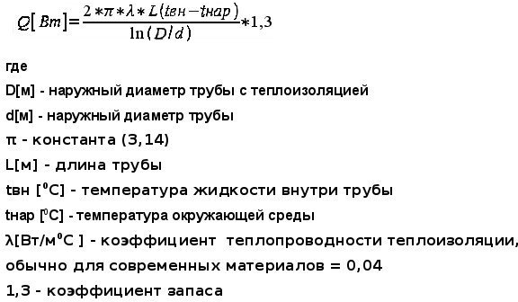
The basic formula for calculating the thermal insulation of pipelines shows the relationship between the magnitude of the heat flux from the operating pipe, covered with a layer of insulation, and its thickness. The formula is applied if the pipe diameter is less than 2 m:
The formula for calculating the thermal insulation of pipes.
ln B = 2πλ [K (tt - to) / qL - Rn]
In this formula:
- λ is the thermal conductivity coefficient of the insulation, W / (m ⁰C);
- K - dimensionless coefficient of additional heat losses through fasteners or supports, some K values can be taken from Table 1;
- tт - temperature in degrees of the transported medium or heat carrier;
- tо - outdoor air temperature, ⁰C;
- qL is the heat flux, W / m2;
- Rн - resistance to heat transfer on the outer surface of the insulation, (m2 ⁰C) / W.
Table 1
| Pipe laying conditions | The value of the coefficient K |
| Steel pipelines are open along the street, through canals, tunnels, open indoors on sliding supports with a nominal diameter of up to 150 mm. | 1.2 |
| Steel pipelines are open along the street, through canals, tunnels, open indoors on sliding supports with a nominal diameter of 150 mm and more. | 1.15 |
| Steel pipelines are open along the street, along canals, tunnels, open indoors on suspended supports. | 1.05 |
| Non-metallic piping laid on overhead or sliding supports. | 1.7 |
| Channelless way of laying. | 1.15 |
The value of the thermal conductivity λ of the insulation is a reference, depending on the selected thermal insulation material. It is recommended to take the temperature of the transported medium tt as the average temperature throughout the year, and of the outside air tо as the average annual temperature. If the insulated pipeline passes in the room, then the ambient temperature is set by the technical design assignment, and in its absence it is taken equal to + 20 ° C. The indicator of resistance to heat transfer on the surface of a heat-insulating structure Rн for outdoor installation conditions can be taken from Table 2.
table 2
| Rн, (m2 ⁰C) / W | DN32 | DN40 | DN50 | DN100 | DN125 | DN150 | DN200 | DN250 | DN300 | DN350 | DN400 | DN500 | DN600 | DN700 |
| tт = 100 ⁰C | 0.12 | 0.10 | 0.09 | 0.07 | 0.05 | 0.05 | 0.04 | 0.03 | 0.03 | 0.03 | 0.02 | 0.02 | 0.017 | 0.015 |
| tт = 300 ⁰C | 0.09 | 0.07 | 0.06 | 0.05 | 0.04 | 0.04 | 0.03 | 0.03 | 0.02 | 0.02 | 0.02 | 0.02 | 0.015 | 0.013 |
| tт = 500 ⁰C | 0.07 | 0.05 | 0.04 | 0.04 | 0.03 | 0.03 | 0.03 | 0.02 | 0.02 | 0.02 | 0.02 | 0.016 | 0.014 | 0.012 |
Note: the value of Rn at intermediate values of the coolant temperature is calculated by interpolation. If the temperature indicator is below 100 ⁰C, the Rn value is taken as for 100 ⁰C.
Indicator B should be calculated separately:
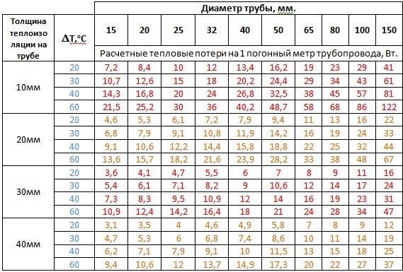
Heat loss table for different pipe thicknesses and thermal insulation.
B = (dfrom + 2δ) / dtr, here:
- diz - outer diameter of the heat-insulating structure, m;
- dtr - outer diameter of the protected pipe, m;
- δ is the thickness of the heat-insulating structure, m.
The calculation of the insulation thickness of pipelines begins with determining the indicator ln B, substituting the values of the outer diameters of the pipe and the thermal insulation structure, as well as the layer thickness, into the formula, after which the parameter ln B is found from the table of natural logarithms. It is substituted into the basic formula together with the indicator of the normalized heat flux qL and calculate. That is, the thickness of the pipeline insulation must be such that the right and left sides of the equation become identical. This thickness value should be taken for further development.
The considered calculation method applied to pipelines with a diameter of less than 2 m.For pipes with a larger diameter, the calculation of insulation is somewhat simpler and is performed both for a flat surface and according to a different formula:
δ = [K (tt - to) / qF - Rn]
In this formula:
- δ is the thickness of the thermal insulation structure, m;
- qF is the value of the normalized heat flux, W / m2;
- other parameters - as in the calculation formula for a cylindrical surface.
How to calculate the thickness using the formula yourself
When the data obtained using an online calculator seems questionable, it is worth trying the analog method using an engineering formula to calculate the thickness of the thermal insulation material. For the calculation, they work according to the following algorithm:
- The formula is used to calculate the thermal resistance of the insulation.
- Calculate the linear heat flux density.
- Calculate the temperature indicators on the inner surface of the insulation.
- They turn to the calculation of the heat balance and the thickness of the insulation according to the formula.
The same formulas are used to compile the algorithm for the online calculator.