6.1. Aerodynamic calculation of supply ventilation systems.
Aerodynamic calculation is carried out in order to determine the dimensions of the cross-section of the air ducts and channels of the supply and exhaust ventilation systems and to determine the pressure that provides the calculated air flow in all sections of the air ducts.
Aerodynamic calculation consists of two stages:
1. Calculation of sections of air ducts of the main direction - highways;
2. Linking branches.
Aerodynamic calculation is performed in the following sequence:
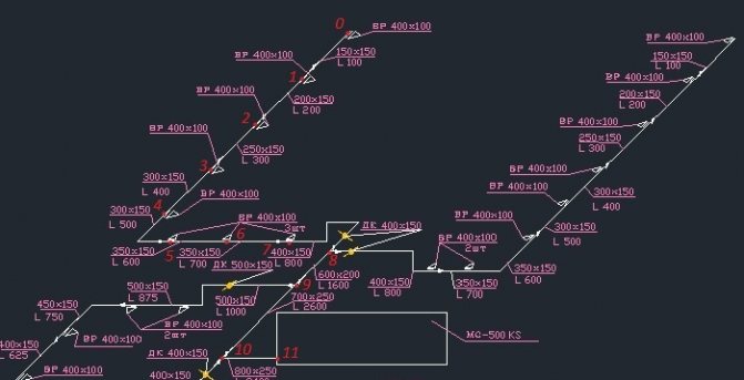
1) The system is divided into separate sections. The lengths of all sections and their costs are taken out on the calculation scheme.
2) The main line is selected. The branch with the maximum length and maximum load is selected as the main highway.
3) We number the sections, starting from the most distant section of the highway.
4) Determine the dimensions of the sections of the design sections by the formula:
The selection of the dimensions of the cross-section of the air ducts is carried out according to the optimal air velocities. The maximum permissible speeds for the supply mechanical ventilation system are taken according to table 3.5.1 of the source [1]:
- for the highway 8 m / s;
- for branches 5 m / s.
5) According to the calculated area f, the dimensions of the duct are selected.
Then the speed is specified using the formula:
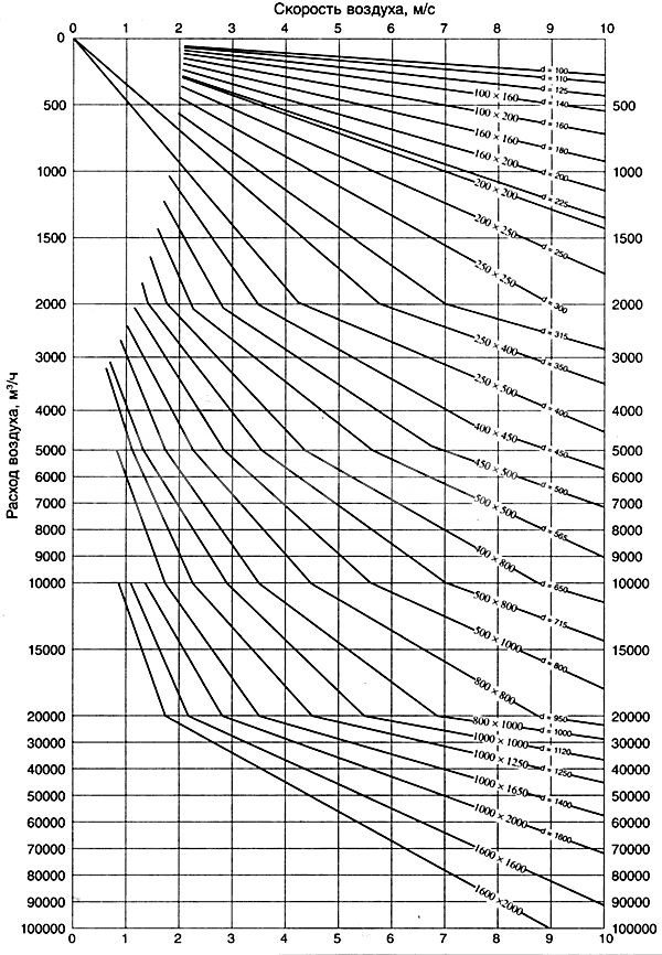
6) Determine the friction pressure loss:
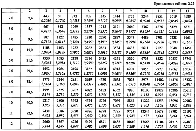
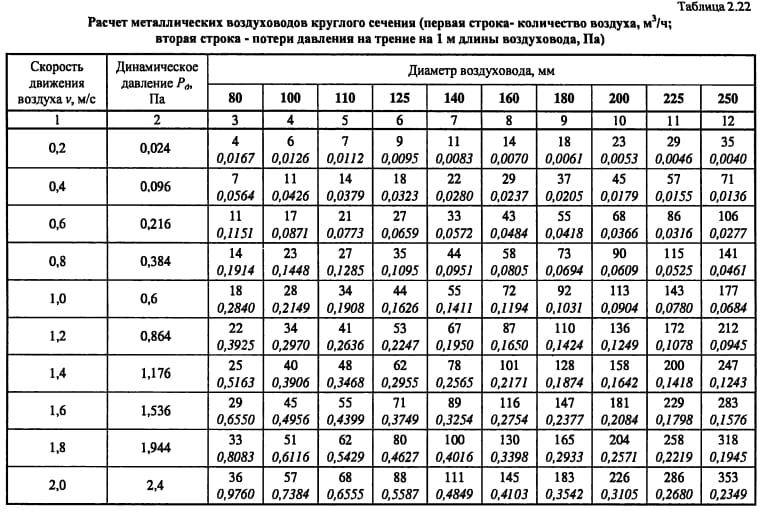
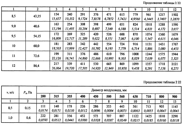
where R is the specific pressure loss due to friction, Pa / m.
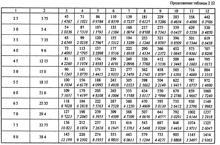
It is taken according to the table. 22.15 of the Designer's Handbook (entrance by equivalent diameter de and air velocity v).
l - section length, m.
Vsh - coefficient taking into account the roughness of the inner surface of the duct channel (for steel Vsh = 1, for channels in brick walls Vsh = 1.36). It is taken according to the table. 22.12 of the Designer Handbook.

7) Determine the pressure loss in local resistances by the formula:
where ∑ζ is the sum of the coefficients of local resistances of the site, taken according to the Designer Handbook;
pD - dynamic pressure, Pa.
Determine the total pressure loss in the calculated area
9) Determine the pressure loss in the system by the formula:
where N is the number of sections of the highway.
p - pressure loss in ventilation equipment.
10) We link the branches, starting with the longest branch. The pressure loss in the branch is equal to the pressure loss in the line from the peripheral section to the common point with the branch:
The discrepancy between the pressure losses along the branches of the air ducts should not exceed 10% of the pressure losses in the parallel sections of the line. If during the calculation it turns out that by changing the diameter it is impossible to equalize the losses, then we install the diaphragms, the throttle - valves or equalize with gratings (gratings of type P and PP are adjustable).
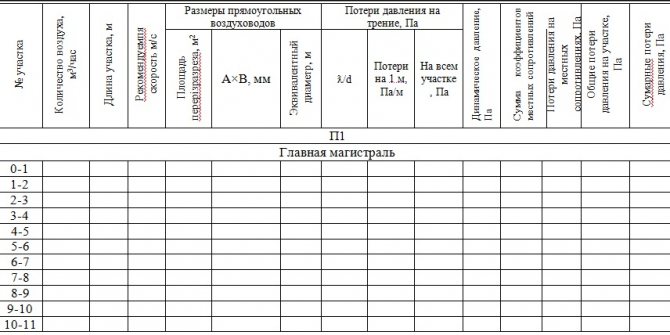
Aerodynamic calculation of the system P1, P2, P3, P4, B1, B2, B3, B4, B5, B6, B7, B8 are summarized in tables No. 6-16. After the calculation, sections of the air ducts are applied to the diagrams with an indication of the costs.
6.2. Aerodynamic calculation of ventilation systems with natural induction of air movement.
When calculating a natural ventilation system, it is necessary that the losses in the system are less than the pressure created by the density difference (available pressure).
When calculating, we try to maintain a discrepancy of 5-10% between the pressure loss in the system and the available pressure, but if it is necessary to increase the losses in the system, then we use adjustable grids.
The available pressure is calculated by the formula:
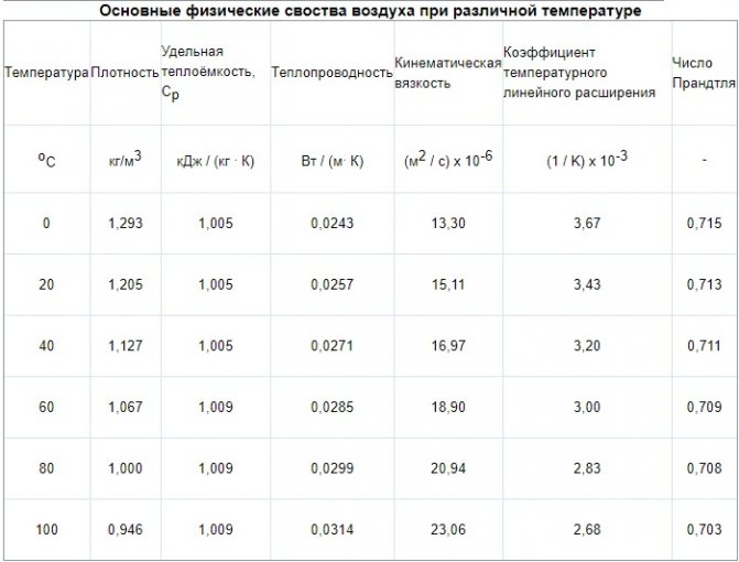
where ρн, ρв - air density at tн and tв, respectively (the calculation is carried out at the outside air temperature tн = 5 о C);
h is the height of the air column, m.

The height of the air column depends on the presence or absence of a supply ventilation system in a given room:
- if the room has a supply ventilation system, then the height of the air column is equal to the distance from the middle of the room height to the mouth of the exhaust shaft;
- if there is only an exhaust system in the room, then the height of the air column is equal to the distance from the middle of the exhaust hole
to the mouth of the exhaust shaft.
The calculation of the ventilation system with natural impulse is carried out in the following order:
1) Determine the highway. For natural draft, this will be the branch for which the available pressure is the smallest.
2) The determination of the cross-section of the ducts is carried out in the same way as the supply mechanical system
3) We calculate the remaining branches in the same way as the mains, comparing the discrepancy with the available pressure.

7. SELECTION OF VENTILATION EQUIPMENT
7.1. Selection of fixed louvered grilles.
The role of the air intake is performed by STD-type louvered grilles. They are mounted in a hole in the wall of the ventilation chamber. Such a constructive solution of the air intake device does not contradict sanitary and hygienic requirements, since there are no external air pollutants near it. The air intake is carried out in accordance with the requirements, according to which the air intake devices should not be lower than 2 m from the ground level.
The selection is made in the following order:
1) for a given air flow rate, select one or more gratings with a total free area
where v is the recommended speed of air movement in the section of the lattice. It is taken equal to 2 - 6 m / s;
Ltot - volumetric flow rate of air passing through the grate, m 3 / h.
f = 13386 / (3600 4) = 0.93 m 2
The number of gratings is determined as
where f1 is the area of the open section of one lattice, m 2.
n = 0.93 / 0.183 = 5 pcs.
a grating of the STD 302 type was adopted with a free area f1 = 0.183 m 2
2) We clarify the speed by the formula
where ffact is the actual total cross-sectional area, m 2.
v = 13386 / (3600 0.915) = 4 m / s
3) We calculate the pressure loss in the grids by the formula:
p = ζ (ρ v 2) / 2,
where ζ is the coefficient of local resistance. For gratings of the STD type is 1.2.
ρ is the density of the outside air during the cold period of the year at a temperature of -32 0 C, ρ = 1.48319 kg / m3.

∆p = 1.2 · (1.48319 · 4 2) / 2 = 14.2 Pa.
Selection of a fixed louvred grille. Table 17
| System no. | L, m 3 / h | Brand | number | Size, mm |
| P1-P4 | 13386 | STD-302 | 5 | 750´1160 |
7.2. Filter selection
1) Selection of filters for the P1 system (supply to the auditorium):
The number of filter cells is determined by the formula:
where L is the volumetric flow rate of air supplied to the hall - 13386m 3 / h.
Li is the throughput of one filter cell; for FYaPb filters it is 1500 m 3 / h. The size of one cell is 518´518 mm.
n '= 13386/1500 = 8.9
Aerodynamic resistance of the cell type: ∆p = 150 Pa.
Filter selection Table 18
| System no. | L, m 3 / h | Brand | Size, mm |
| P1 | 13494 | FYaPb | 518´518 |
| P2 | 648 | FYaPb | 518´518 |
| P3 | 576 | FYaPb | 518´518 |
| P4 | 234 | FYaPb | 518´518 |
7.3. Selection of the insulated air valve.
The insulated air damper is designed to prevent unreasonable heat loss at a time when the ventilation system is not working. The type of damper, overall dimensions and free cross-sectional area for air passage are selected according to a given flow rate.
Dampers selection method:
1) for a given air flow, the type of damper and the area of the free section are selected from the table.
2) Determine the speed of air movement in the living section
valve according to the formula:

v = 13386 / (3600 1.48) = 2.5 m / s;
Stage one
This includes the aerodynamic calculation of mechanical air conditioning or ventilation systems, which includes a number of sequential operations. A perspective diagram is drawn up, which includes ventilation: both supply and exhaust, and is prepared for the calculation.
The dimensions of the cross-sectional area of the air ducts are determined depending on their type: round or rectangular.
Formation of the scheme
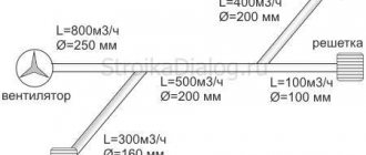
The diagram is drawn up in perspective with a scale of 1: 100. It indicates the points with the located ventilation devices and the consumption of air passing through them.
Here you should decide on the trunk - the main line on the basis of which all operations are carried out. It is a chain of sections connected in series, with the greatest load and maximum length.
When building a highway, you should pay attention to which system is being designed: supply or exhaust.
Supply
Here, the billing line is built from the most distant air distributor with the highest consumption. It passes through supply elements such as air ducts and air handling units up to the point where air is drawn in. If the system is to serve several floors, then the air distributor is located on the last one.
Exhaust
A line is being built from the most remote exhaust device, which maximizes the consumption of air flow, through the main line to the installation of the hood and further to the shaft through which air is released.
If ventilation is planned for several levels and the installation of the hood is located on the roof or attic, then the calculation line should start from the air distribution device of the lowest floor or basement, which is also included in the system. If the hood is installed in the basement, then from the air distribution device of the last floor.
The entire calculation line is divided into segments, each of them is a section of the duct with the following characteristics:
- duct of uniform cross-sectional size;
- from one material;
- with constant air consumption.
The next step is numbering the segments. It starts with the most distant exhaust device or air distributor, each assigned a separate number. The main direction - the highway is highlighted with a bold line.
Further, on the basis of an axonometric diagram for each segment, its length is determined, taking into account the scale and air consumption. The latter is the sum of all the values of the consumed air flow flowing through the branches that are adjacent to the line. The value of the indicator, which is obtained as a result of sequential summation, should gradually increase.
Determination of dimensional values of air duct cross-sections
Produced on the basis of indicators such as:
- air consumption in the segment;
- the normative recommended values of the air flow speed are: on highways - 6m / s, in mines where air is taken - 5m / s.
The preliminary dimensional value of the duct on the segment is calculated, which is brought to the nearest standard. If a rectangular duct is selected, then the values are selected based on the dimensions of the sides, the ratio between which is no more than 1 to 3.
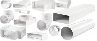
Duct types
Air ducts are elements of the system that are responsible for the transfer of exhaust and fresh air. It includes main tapered pipes, elbows and half-elbows, as well as a variety of adapters. They differ in material and sectional shape.
The area of application and the specifics of air movement depend on the type of air duct. There is the following material classification:
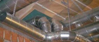
- Steel - rigid, thick-walled air ducts.
- Aluminum - flexible, thin-walled.
- Plastic.
- Cloth.
According to their shape, sections are divided into round sections of different diameters, square and rectangular.
Stage two
The aerodynamic drag figures are calculated here. After choosing the standard cross-sections of the air ducts, the value of the air flow rate in the system is specified.
Calculation of friction pressure loss
The next step is to determine the specific friction pressure loss based on tabular data or nomograms.In some cases, a calculator can be useful to determine indicators based on a formula that allows you to calculate with an error of 0.5 percent. To calculate the total value of the indicator characterizing the pressure loss over the entire section, you need to multiply its specific indicator by the length. At this stage, the roughness correction factor should also be taken into account. It depends on the magnitude of the absolute roughness of a particular duct material, as well as the speed.
Calculating the dynamic pressure indicator on a segment
Here, an indicator characterizing the dynamic pressure in each section is determined based on the values:
- air flow rate in the system;
- the density of the air mass under standard conditions, which is 1.2 kg / m3.
Determination of values of local resistances in sections
They can be calculated based on the coefficients of local resistance. The obtained values are summarized in a tabular form, which includes the data of all sections, and not only straight segments, but also several fittings. The name of each element is entered in the table, the corresponding values and characteristics are also indicated there, according to which the coefficient of local resistance is determined. These indicators can be found in the relevant reference materials for the selection of equipment for ventilation units.
In the presence of a large number of elements in the system or in the absence of certain values of the coefficients, a program is used that allows you to quickly carry out cumbersome operations and optimize the calculation as a whole. The total resistance value is determined as the sum of the coefficients of all elements of the segment.
Calculation of pressure losses on local resistances
Having calculated the final total value of the indicator, they proceed to calculating the pressure losses in the analyzed areas. After calculating all segments of the main line, the obtained numbers are summed up and the total value of the resistance of the ventilation system is determined.
General information
Aerodynamic calculation is a technique for determining the dimensions of the cross-section of air ducts to level the pressure losses, maintain the speed of movement and the design volume of pumped air.
With the natural ventilation method, the required pressure is given initially, but the cross-section must be determined. This is due to the action of gravitational forces that induce air masses to be drawn into the room from the ventilation shafts. With the mechanical method, the fan works, and it is necessary to calculate the gas pressure, as well as the cross-sectional area of the duct. The maximum speeds inside the ventilation duct are used.
To simplify the technique, air masses are taken as liquid with zero percent compression. In practice, this is true, since in most systems the pressure is minimal. It is formed only from local resistance, when it collides with the walls of the air ducts, as well as at places where the area changes. This was confirmed by numerous experiments carried out according to the method described in GOST 12.3.018-79 “Occupational Safety Standards System (SSBT). Ventilation systems. Aerodynamic Test Methods ".
The technique involves the selection of the area and shape of the section for each section of the ventilation system. If we take it as a whole, then the definition of losses will be conditional, not corresponding to the real picture. In addition to the movement itself, the injection is additionally calculated.
Aerodynamic calculations of ventilation ducts are carried out with a different number of known data. In one case, the calculation starts from zero, and in the other, more than half of the initial parameters are already known.
Stage three: linking branches
When all the necessary calculations have been carried out, it is necessary to link several branches.If the system serves one level, then the branches that are not included in the trunk are connected. The calculation is carried out in the same manner as for the main line. The results are recorded in a table. In multi-storey buildings, floor branches at intermediate levels are used for linking.
Linkage criteria
Here, the values of the sum of losses are compared: pressure along the sections to be linked with a parallel-connected line. It is necessary that the deviation is no more than 10 percent. If it is found that the discrepancy is greater, then the linking can be carried out:
- by selecting the appropriate dimensions for the cross-section of the air ducts;
- by installing on branches of diaphragms or butterfly valves.
Sometimes, to carry out such calculations, you just need a calculator and a couple of reference books. If it is required to carry out an aerodynamic calculation of the ventilation of large buildings or industrial premises, then an appropriate program will be needed. It will allow you to quickly determine the dimensions of the sections, pressure losses both in individual sections and in the entire system as a whole.
https://www.youtube.com/watch?v=v6stIpWGDow Video can’t be loaded: Ventilation system design. (https://www.youtube.com/watch?v=v6stIpWGDow)
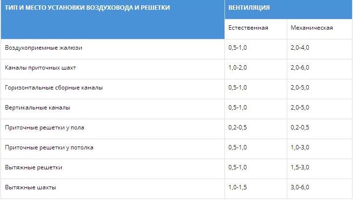
The main requirement for all types of ventilation systems is to ensure the optimal frequency of air exchange in rooms or specific work areas. Taking this parameter into account, the inner diameter of the duct is designed and the fan power is selected. In order to guarantee the required efficiency of the ventilation system, the calculation of the head pressure losses in the ducts is carried out, these data are taken into account when determining the technical characteristics of the fans. Recommended air flow rates are shown in Table 1.
Method of admissible speeds
When calculating the air duct network using the method of permissible speeds, the optimal air speed is taken as the initial data (see table). Then the required section of the duct and the pressure loss in it are considered.
Procedure for aerodynamic calculation of air ducts using the method of permissible speeds:
- Draw a diagram of the air distribution system. For each section of the duct, indicate the length and amount of air passing in 1 hour.
- We start the calculation from the farthest and most loaded areas from the fan.
- Knowing the optimal air speed for a given room and the volume of air passing through the duct in 1 hour, we determine the appropriate diameter (or section) of the duct.
- Calculating frictional pressure loss Ptr.
- According to the tabular data, we determine the sum of local resistances Q and calculate the pressure loss for local resistance z.
- The available pressure for the next branches of the air distribution network is determined as the sum of the pressure losses in the sections located before this branch.
In the calculation process, it is necessary to consistently link all the branches of the network, equating the resistance of each branch to the resistance of the most loaded branch. This is done using diaphragms. They are installed on lightly loaded sections of air ducts, increasing the resistance.
Tab. No. 1. Recommended air speed for different rooms
| Appointment | Basic requirement | ||||
| Noiselessness | Min. head loss | ||||
| Trunk channels | Main channels | Branches | |||
| Inflow | Hood | Inflow | Hood | ||
| Living spaces | 3 | 5 | 4 | 3 | 3 |
| Hotels | 5 | 7.5 | 6.5 | 6 | 5 |
| Institutions | 6 | 8 | 6.5 | 6 | 5 |
| Restaurants | 7 | 9 | 7 | 7 | 6 |
| The shops | 8 | 9 | 7 | 7 | 6 |
Based on these values, the linear parameters of the ducts should be calculated.
Algorithm for calculating the loss of air pressure
The calculation must begin with drawing up a diagram of the ventilation system with the obligatory indication of the spatial arrangement of air ducts, the length of each section, ventilation grilles, additional equipment for air purification, technical fittings and fans. Losses are determined first for each separate line, and then they are summed up.For a separate technological section, the losses are determined using the formula P = L × R + Z, where P is the air pressure loss in the calculated section, R is the losses per linear meter of the section, L is the total length of the air ducts in the section, Z is the losses in the additional fittings of the system ventilation.
To calculate the pressure loss in a circular duct, the formula Ptr is used. = (L / d × X) × (Y × V) / 2g. X is the tabular coefficient of air friction, depends on the material of the air duct, L is the length of the calculated section, d is the diameter of the air duct, V is the required air flow rate, Y is the air density taking into account the temperature, g is the acceleration of falling (free). If the ventilation system has square ducts, then table No. 2 should be used to convert round values to square ones.
Tab. No. 2. Equivalent diameters of round ducts for square
| 150 | 200 | 250 | 300 | 350 | 400 | 450 | 500 | |
| 250 | 210 | 245 | 275 | |||||
| 300 | 230 | 265 | 300 | 330 | ||||
| 350 | 245 | 285 | 325 | 355 | 380 | |||
| 400 | 260 | 305 | 345 | 370 | 410 | 440 | ||
| 450 | 275 | 320 | 365 | 400 | 435 | 465 | 490 | |
| 500 | 290 | 340 | 380 | 425 | 455 | 490 | 520 | 545 |
| 550 | 300 | 350 | 400 | 440 | 475 | 515 | 545 | 575 |
| 600 | 310 | 365 | 415 | 460 | 495 | 535 | 565 | 600 |
| 650 | 320 | 380 | 430 | 475 | 515 | 555 | 590 | 625 |
| 700 | 390 | 445 | 490 | 535 | 575 | 610 | 645 | |
| 750 | 400 | 455 | 505 | 550 | 590 | 630 | 665 | |
| 800 | 415 | 470 | 520 | 565 | 610 | 650 | 685 | |
| 850 | 480 | 535 | 580 | 625 | 670 | 710 | ||
| 900 | 495 | 550 | 600 | 645 | 685 | 725 | ||
| 950 | 505 | 560 | 615 | 660 | 705 | 745 | ||
| 1000 | 520 | 575 | 625 | 675 | 720 | 760 | ||
| 1200 | 620 | 680 | 730 | 780 | 830 | |||
| 1400 | 725 | 780 | 835 | 880 | ||||
| 1600 | 830 | 885 | 940 | |||||
| 1800 | 870 | 935 | 990 |
The horizontal is the height of the square duct, and the vertical is the width. The equivalent value of the circular section is at the intersection of the lines.
The air pressure losses in the bends are taken from table no. 3.
Tab. No. 3. Pressure loss at bends
To determine the pressure loss in the diffusers, the data from Table 4 are used.
Tab. No. 4. Pressure loss in diffusers
Table 5 gives a general diagram of losses in a straight section.
Tab. No. 5. Diagram of air pressure losses in straight air ducts
All individual losses in this section of the duct are summed up and corrected with table No. 6. Tab. No. 6. Calculation of the decrease in flow pressure in ventilation systems
During design and calculations, existing regulations recommend that the difference in the magnitude of pressure losses between individual sections does not exceed 10%. The fan should be installed in the section of the ventilation system with the highest resistance, the farthest air ducts should have the lowest resistance. If these conditions are not met, then it is necessary to change the layout of air ducts and additional equipment, taking into account the requirements of the provisions.
When air moves in ventilation systems, energy loss occurs, which is usually expressed in air pressure drops in certain sections of the system and in the system as a whole. Aerodynamic calculation is carried out in order to
determining the dimensions of the cross-section of network sections.
In the latter case, the selection of the dimensions of the cross-section of the air ducts, as a rule, is carried out according to the maximum permissible air velocities.
The aerodynamic calculation of the ventilation system consists of two stages: the calculation of the sections of the main direction - the main line and the linking of all other sections of the system.
The calculation is carried out in the following sequence.
1. Determine the loads of individual design sections. For this, the system is divided into separate sections. The calculated section is characterized by a constant air flow along the length. Tees serve as the boundaries between the individual sections.
The estimated costs for the sections are determined by summing the costs for individual branches, starting with the peripheral sections. The flow rates and the length of each section indicate the axonometric diagram of the calculated system.
2. The main (main) direction is selected, for which the most extended chain of sequentially located calculated sections is identified. With an equal length of the highways, the most loaded one is chosen as the design one.
3. The numbering of highway sections usually begins with a section with a lower flow rate. Consumption, length and the results of subsequent calculations are entered in table. aerodynamic calculation.
4. Given the velocities of air movement u rivers and the air flow rate in the section, the cross-section of the duct is determined:
The speed is calculated as you approach the fan.
5. Determine the diameter d, mm, the actual speed of air movement in it u fact, m / s, the specific pressure loss due to friction R, Pa / m and the total pressure loss along the length Rl.If the material of the duct is different from steel, then a correction factor n is introduced depending on the material of the duct used:
For round ducts:
For rectangular ducts:
6. Next, the pressure loss for local resistances is determined. for each section, all local resistances are written out separately and they are summed up by sections. It should be remembered that the local resistances of the tees must be attributed to the area with a lower load.
7. Pressure loss DР, Pa, in the duct section is determined by the formula:
DP = Rnl + Z,
where R is the specific pressure loss per 1 m of the steel duct, Pa / m;
Z - pressure loss in local resistances;
n- correction for the roughness of the walls of the duct It is taken depending on the material of the duct
8. The pressure loss in local resistances Z, Pa, is calculated by the formula
where Р д - dynamic air pressure in the area, Pa
Sx - the sum of the coefficients of local resistance
r - air density, kg / m 3;
u is the speed of air movement in the duct, m / s.
9. The total pressure loss in the system is equal to the sum of the losses along the line and in the ventilation equipment:
DR = S (Rnl + Z) magician
For systems with mechanical induction of air movement, the required fan pressure is determined from the value of the total pressure loss in the system. The calculation results are entered in the table.
10. The linking of the remaining sections (branches) is carried out, starting with the longest branches. The method of linking branches is similar to the calculation of sections of the main direction. When linking a branch, the previously calculated pressure losses in the main line and the diameters of the air ducts cannot be recalculated:
P rasp.out = S (Rnl + Z) parallel uch
The dimensions of the cross-sections of the branches are considered to be matched if the relative discrepancy of losses in parallel sections does not exceed 15%:
Comments:
- Initial data for calculations
- Where to start? Calculation order
The heart of any ventilation system with mechanical airflow is the fan, which creates this flow in the ducts. The power of the fan directly depends on the pressure that must be created at the outlet from it, and in order to determine the magnitude of this pressure, it is required to calculate the resistance of the entire system of channels.
To calculate the pressure loss, you need the layout and dimensions of the duct and additional equipment.
Initial data for calculations
When the diagram of the ventilation system is known, the dimensions of all air ducts are selected and additional equipment is determined, the diagram is depicted in a frontal isometric projection, that is, a perspective view. If it is carried out in accordance with the current standards, then all the information necessary for the calculation will be visible on the drawings (or sketches).
- With the help of floor plans, you can determine the lengths of the horizontal sections of air ducts. If, on the axonometric diagram, the elevation marks are put on which the channels pass, then the length of the horizontal sections will also become known. Otherwise, sections of the building with laid routes of air ducts will be required. And as a last resort, when there is not enough information, these lengths will have to be determined using measurements at the installation site.
- The diagram should show with the help of symbols all additional equipment installed in the channels. These can be diaphragms, motorized dampers, fire dampers, as well as devices for distributing or exhausting air (grilles, panels, umbrellas, diffusers). Each piece of this equipment creates resistance in the air flow path, which must be taken into account when calculating.
- In accordance with the standards on the diagram, air flow rates and channel sizes should be indicated next to the conventional images of the air ducts. These are the defining parameters for calculations.
- All shaped and branching elements should also be reflected in the diagram.
If such a diagram does not exist on paper or in electronic form, then you will have to draw it at least in a rough version; you cannot do without it when calculating.
Back to the table of contents
Where to start?
Diagram of head loss per meter of duct.
Very often you have to deal with fairly simple ventilation schemes, in which there is an air duct of the same diameter and there is no additional equipment. Such circuits are calculated quite simply, but what if the circuit is complex with many branches? According to the method for calculating pressure losses in air ducts, which is described in many reference publications, it is necessary to determine the longest branch of the system or the branch with the greatest resistance. It is rarely possible to find out such resistance by eye, therefore it is customary to calculate along the longest branch. After that, using the air flow rates indicated on the diagram, the entire branch is divided into sections according to this feature. As a rule, the costs change after branching (tees) and when dividing it is best to focus on them. There are other options, for example, supply or exhaust grilles built directly into the main duct. If this is not shown on the diagram, but there is such a lattice, it will be necessary to calculate the flow rate after it. Sections are numbered starting from the farthest from the fan.
Back to the table of contents
Calculation order
The general formula for calculating the pressure loss in the ducts for the entire ventilation system is as follows:
H B = ∑ (Rl + Z), where:
- H B - pressure loss in the entire duct system, kgf / m²;
- R - friction resistance of 1 m of an air duct of equivalent cross-section, kgf / m²;
- l is the length of the section, m;
- Z is the amount of pressure lost by the air flow in local resistances (shaped elements and additional equipment).
Note: the value of the cross-sectional area of the duct involved in the calculation is taken initially as for the circular shape of the duct. Friction resistance for rectangular ducts is determined by the cross-sectional area equivalent to a round one.
The calculation starts from the most distant site number 1, then go to the second site and so on. The results of calculations for each section are added, which is indicated by the mathematical sign of the summation in the calculation formula. The parameter R depends on the diameter of the channel (d) and the dynamic pressure in it (P d), and the latter, in turn, depends on the speed of the air flow. The coefficient of absolute wall roughness (λ) is traditionally taken as for an air duct made of galvanized steel and is 0.1 mm:
R = (λ / d) P d.
It makes no sense to use this formula in the process of calculating pressure losses, since the values of R for various air velocities and diameters have already been calculated and are reference values (R.V.Schekin, I.G. Staroverov - reference books). Therefore, it is simply necessary to find these values in accordance with the specific conditions of movement of air masses and substitute them in the formula. Another indicator, the dynamic pressure P d, which is associated with the parameter R and participates in the further calculation of local resistances, is also a reference value. Given this relationship between the two parameters, they are listed together in the reference tables.
The value Z of pressure losses in local resistances is calculated by the formula:
Z = ∑ξ P d.
The summation sign means that you need to add the calculation results for each of the local resistances in a given section. In addition to the already known parameters, the formula contains the coefficient ξ. Its value is dimensionless and depends on the type of local resistance. The parameter values for many elements of ventilation systems are calculated or determined empirically, therefore, they are in the reference literature.The local resistance coefficients of ventilation equipment are often indicated by the manufacturers themselves, having determined their values experimentally in production or in a laboratory.
Having calculated the length of section No. 1, the number and type of local resistances, all parameters should be correctly determined and substituted into the calculation formulas. Having received the result, proceed to the second section and further, to the fan itself. At the same time, one should not forget about that section of the air duct, which is already located behind the ventilation unit, because the fan pressure should also be enough to overcome its resistance.
Having finished the calculations along the longest branch, they make the same ones along the neighboring branch, then along the next, and so on until the very end. Typically, these branches all have many common areas, so the calculations will go faster. The purpose of determining the pressure losses on all branches is their common coordination, because the fan must distribute its flow evenly throughout the system. That is, ideally, the pressure loss in one branch should differ from the other by no more than 10%. In simple terms, this means that the branch closest to the fan should have the highest resistance, and the farthest branch should have the lowest. If this is not the case, it is recommended to return to the recalculation of the diameters of the air ducts and the air velocities in them.
echo get_the_author_meta ("display_name", $ auhor); ?>
The resistance to the passage of air in a ventilation system is mainly determined by the speed of air movement in this system. As the speed increases, so does the resistance. This phenomenon is called pressure loss. The static pressure generated by the fan causes air movement in the ventilation system, which has a certain resistance. The higher the resistance of such a system, the lower the air flow transported by the fan. Calculation of friction losses for air in air ducts, as well as the resistance of network equipment (filter, silencer, heater, valve, etc.) can be performed using the corresponding tables and diagrams specified in the catalog. The total pressure drop can be calculated by summing the resistance values of all elements of the ventilation system.
Determination of the speed of air movement in air ducts:
Possible errors and consequences
The cross-section of the air ducts is selected according to the tables, where the unified dimensions are indicated, depending on the dynamic pressure and the speed of movement. Often inexperienced designers round the velocity / pressure parameters downwards, hence the change in cross-section downwards. This can lead to excessive noise or the inability to pass the required volume of air per unit of time.
Errors are also allowed in determining the length of the duct segment. This leads to a possible inaccuracy in the selection of equipment, as well as to an error in the calculation of the gas velocity.
Project example
The aerodynamic part, like the entire project, requires a professional approach and careful attention to the details of a particular object.
performs a qualified selection of ventilation systems in accordance with applicable standards, with full technical support. We provide services in Moscow and the region, as well as neighboring regions. Detailed information from our consultants, all methods of contacting them are indicated on the "Contacts" page.