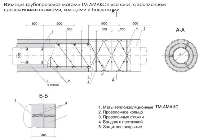
Pipeline insulation design
Insulation design for pipelines with an outer diameter of 15 to 159 mm, for a heat-insulating layer made of stitched glass staple fiber mats on a synthetic binder, stitched mats made of mineral and basalt wool, mats made of basalt or glass super-thin fiber, the following fastening is used:
- for pipelines with an outer diameter of the heat-insulating layer not exceeding 200 mm - fastening with a wire with a diameter of 1.2-2 mm in a spiral around the heat-insulating layer, while the spiral is fixed on wire rings along the edges of the mats. If mats are used in the plates, then the edges of the plates are stitched with glass thread, silica thread, roving or wire with a diameter of 0.8 mm;
Thermal insulation construction made of fibrous materials for pipes with a diameter of not more than 200 mm.
1. Mats or canvases made of fiberglass or mineral wool; 2. Spiral fastening from a wire with a diameter of 1.2 - 2.0 mm, 3. A ring from a wire with a diameter of 1.2 - 2.0 mm, 4. Covering layer.
- for pipelines with an outer diameter of 57-159 mm:
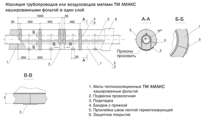
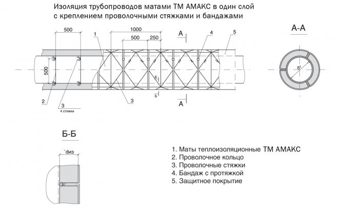
- when laying mats in one layer - with bandages from tape 0.7 × 20 mm. The step of installing the bands depends on the size of the products used, but not more than 500 mm. When laying mats with a width of 1000 mm, the bandages are recommended to be installed with a pitch of 450 mm with an offset of 50 mm from the edge of the product. On a product with a width of 500 mm, 2 bands should be installed;
Insulation of pipelines with an outer diameter of 57 to 219 mm.
but. Insulation in one layer; b. Insulation in two layers.
1. heat-insulating layer made of fibrous materials, 2. ring made of wire with a diameter of 1.2 - 2.0 mm, 3. bandage with a buckle, 4. cover layer.
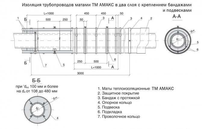
- when laying mats in two layers - with rings made of wire with a diameter of 2 mm for the inner layer of two-layer structures, with bandages - for the outer layer of two-layer heat-insulating structures. Bandages made of tape 0.7 × 20 mm are installed on the outer layer in the same way as in a single-layer construction.
Black steel bandages should be painted to prevent corrosion. The edges of the covers are sewn together as described above. With two-layer insulation, the edges of the inner layer plates are not stitched together. When molded products, cylinders or segments are used for thermal insulation of pipelines, their fastening is carried out with bandages. Two bands are installed when insulated with cylinders. When insulating with segments, it is recommended to install bands with a pitch of 250 mm with a product length of 1000 mm.
The structure of the insulation of pipelines with an outer diameter of 219 mm and more for the heat-insulating layer of mats, the following fastening is used:
- when laying products in one layer - bandages made of tape 0.7 × 20 mm and hangers made of wire with a diameter of 1.2 mm. The hangers are evenly spaced between the bands and are attached to the pipeline. Under the pendants, fiberglass pads are installed when using uncoated mats (Fig. 2.160). When using mats in the covers, pads are not installed. Fiberglass covers are stitched;
- when laying products in two layers with rings made of wire with a diameter of 2 mm and hangers made of wire with a diameter of 1.2 mm for the inner layer of two-layer structures. The second layer pendants are attached to the first layer pendant from below. Bandages made of tape 0.7 × 20 mm are installed on the outer layer in the same way as in a single-layer construction.
Insulation of pipelines with an outer diameter of 219 mm and more with heat-insulating materials made of fibrous materials in one layer.
1 - suspension, 2 - heat-insulating layer, 3 - support bracket (support ring), 4 - bandage with buckle. 5 - lining, 6 - cover layer.
The thermal insulation layer is laid with a thick seal.In two-layer constructions, the mats of the second layer should overlap the seams of the inner layer. For pipelines with an outer diameter of 273 mm and more, in addition to mats, mineral wool slabs with a density of 35-50 kg / m3 can be used, although the optimal field of application is for pipelines with an outer diameter of 530 mm and more. When insulating with slabs, the heat-insulating layer can be fastened with bandages and suspensions. The arrangement of fasteners - bands, hangers and rings (with two-layer insulation) is selected taking into account the length of the plates used. Under the pendants, lining made of rolled fiberglass or roofing material is installed. When using slabs cached with fiberglass, glass mat, fiberglass, backings are not installed. Plates are laid with the long side along the pipeline
Insulation of a pipeline with an outer diameter of 219 mm or more with heat-insulating materials made of fibrous materials in two layers:
1 - heat-insulating layer, 2 - bandage with a buckle, 3 - support ring, 4 - cover layer, 5 - stitching (for products in plates), 6 - pendant, 7 - lining, 8 - wire ring.
In heat-insulating structures with a thickness of less than 100 mm, when using a metal protective coating, support brackets should be installed on horizontal pipelines. The clamps are installed on horizontal pipelines with a diameter of 108 mm and above with a step of 500 mm along the length of the pipeline. On pipelines with an outer diameter of 530 mm and more, three brackets are installed in diameter at the top of the structure and one at the bottom. Support brackets are made of aluminum or galvanized steel (depending on the material of the protective coating) with a height corresponding to the thickness of the insulation.
In horizontal heat-insulating structures of pipelines with a diameter of 219 mm and more with positive temperatures and an insulation thickness of 100 mm or more, support rings are installed. For pipelines with negative temperatures in the supporting structures there should be gaskets made of fiberglass, wood or other low-thermal conductivity materials to eliminate "cold bridges".
When insulating with shape-stable thermal insulation materials such as cylinders, mineral wool or fiberglass segments, as well as KVM-50 mats with vertical fiber orientation (manufactured by Isover) or Lamella Mat, support structures for horizontal sections are not required.
Insulation design for vertical pipelines with an outer diameter of up to 476 mm. The heat-insulating layer is fastened with bandages and wire rings. To prevent slipping of rings and bandages, wire strings with a diameter of 1.2 or 2 mm should be installed.
On vertical pipelines with an outer diameter of 530 mm and more, the heat-insulating layer is fastened on a wire frame with the installation of wire strings that prevent the fastening elements (rings, bands) from sliding off. Rings made of wire with a diameter of 2-3 mm are installed along the length of the pipeline on its surface with a pitch of 500 mm for slabs 1000 mm long and 500 mm wide and mats 500 and 1000 mm wide. Bundles of wire ties with a diameter of 1.2 mm are attached to the rings with a step along the arc of the ring of 500 mm.
There are four screeds in a bundle when insulating in one layer and six - when insulating in two layers. When using mats with a width of 1000 mm, the screeds pierce the thermal insulation layers and fasten them crosswise. When using mats with a width of 500 mm and slabs with a width of 500 mm, the screeds pass at the joints of the products.
Bandages made of tape 0.7 × 20 mm with buckles are installed with a step depending on the width of the product, 2-З pcs. per product (plate or mat 1000-1250 mm wide) with single-layer insulation and along the outer layer with two-layer insulation. Instead of bandages, rings made of wire with a diameter of 2 mm can be installed along the inner layer of two-layer insulation.
When using mats with a width of 500 mm, two bands (or rings) should be installed on the product.The edges of the mats in the covers are sewn with 0.8 mm wire or glass fiber, depending on the type of cover. The strings can be attached to unloading devices, which are installed with a step of 3-4 m in height, or rings made of wire with a diameter of 5 mm, welded to the surface of the pipeline or its other elements.
Insulation design for vertical pipelines, unloading devices are installed with a step of 3-4 m in height.
When insulating cold water pipelines, pipelines transporting substances with negative temperatures, as well as pipelines of heating networks of underground laying, galvanized wire, galvanized steel or painted steel bands should be used for fastening structural elements.
> Technologies for installation of thermal insulation of pipelines
GOST 23307-78 Thermal insulation mats made of mineral wool vertically layered. Technical conditions
STATE STANDARD OF THE UNION OF SSR
HEAT-INSULATING MINERAL WOOL VERTICAL-LAYERED MATS
TECHNICAL CONDITIONS
GOST 23307-78
(ST SEV 5850-86)
COMMITTEE OF STANDARDIZATION AND METROLOGY OF THE USSR
Moscow
STATE STANDARD OF THE UNION OF SSR
| HEAT-INSULATING MINERAL WOOL VERTICAL-LAYERED MATS Technical | GOST 23307-78 ( STCMEA5850-86) |
Date of introduction from 01.07.79
This standard applies to thermal insulation vertically laminated mineral wool mats, consisting of strips cut from mineral wool boards and glued to a protective covering material in a position in which the layers of mineral wool are located perpendicular to the protective covering material.
Heat-insulating vertical-layered mats are intended for thermal insulation of pipelines with a diameter of over 108 mm and apparatus at a temperature of the insulated surfaces from minus 120 to plus 300 ° C.
1.1. Mats, depending on the density (bulk density), are divided into grades 75 and 125.
(Modified edition, Amendment No. 1).
1.2. The dimensions of the mats must correspond to those given in table. 1 and in the drawing.
1.3. The designation of the mat should consist of its abbreviated name, the brand of the mat, the brand of the covering material specified in the standards or technical specifications, the dimensions along the length, width and thickness of the mat in millimeters separated by dots, and the number of this standard.
An example of a conventional designation of a 75 mat on a S-RK glass roofing material, 3000 mm long, 1000 mm wide and 60 mm thick:
MVS-75-S-RK-3000.1000.60 GOST 23307-78
Table 1
| Name of the main dimensions | Nominal dimensions, mm |
| Length l | 600-8000 |
| Width b | 750-1260 |
| Thickness h | 40-100 at intervals of 10 |
| The width of the mineral wool strip m (equal to the thickness of the slabs) for grades: | |
| 75 | 60-100 at intervals of 10 |
| 125 | 50-80 at intervals of 10 |
| The width of the longitudinal edge (the difference between the width of the covering material and the length of the mineral wool strip) k, not less | 40 to 50 |
(Modified edition, Amendments No. 1, 2).
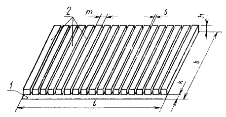
1 - cover material; 2 - mineral wool stripes.
2.1. Mats must be manufactured in accordance with the requirements of this standard for technological regulations, approved in the prescribed manner.
2.2. For the manufacture of mats, plates of mineral wool on a synthetic binder of grades 75 and 125 in accordance with GOST 9573-82 should be used.
(Modified edition, Amendment No. 1).
2.3. The following materials should be used as protective covering materials: roofing material according to GOST 10923-82, glass roofing material according to GOST 15879-70, duplicated aluminum foil, rolled fiberglass plastic for thermal insulation and foil roofing material according to the manufacturer's specifications.
Bitumen grades BN70 / 30 and BN90 / 10 in accordance with GOST 6617-76, polyethylene film in accordance with GOST 10354-82 are used as an adhesive.
Note. It is allowed, upon agreement between the manufacturer and the consumer, to use other covering and adhesive materials.
2.4. Limit deviations of the size of the mats should not exceed:
| by lenght | + 3 %; -1 % |
| in width | ± 10 mm |
| by thickness | + 3; 0 mm (for 40, 50) |
| + 5; 0 mm (for 60, 70, 80, 90, 100). |
The difference in thickness of the mat should not exceed 5 mm.
2.3; 2.4. (Modified edition, Amendment No. 2).
2.5. The gap between the mineral wool strips s that make up the mat must not exceed 2 mm.
2.6. In terms of physical and mechanical indicators, mats must meet the requirements specified in table. 2.
table 2
| Indicator name | Value for brand mats | |
| 75 | 125 | |
| Density, kg / m3 | 50 to 75 | St. 75 to 125 |
| Compressibility under a specific load of 2000 Pa (0.02 kgf / cm2,%, no more | 3 | 2 |
| Thermal conductivity, W / (m × K), no more, at temperature; | ||
| a) (298 ± 5) K | 0,048 | 0,046 |
| b) (398 ± 5) K | 0,083 | 0,081 |
2.7. The mats must withstand the test for the adhesion of mineral wool strips to the covering material specified in clause 4.10.
2.6; 2.7. (Modified edition, Amendment No. 2).
3.1. Acceptance of mats should be carried out in accordance with the requirements of GOST 26281-84 and this standard.
3.2. The volume of a batch of mats is set in the amount of no more than a shift production.
3.3. The dimensions of the mats, the difference in thickness, the gap between the mineral wool strips, the width of the longitudinal edge, density, compressibility, moisture, the strength of adhesion of the mineral wool strips to the covering material of each mat included in the sample are determined for each batch.
Thermal conductivity is determined once a quarter and with each change in raw materials and production technology on three mats that have passed acceptance tests.
3.4. A batch of mats not accepted based on the results of control of dimensions, thickness variation, gap between mineral wool strips, width of the longitudinal edge, adhesion strength, is subjected to continuous control according to the indicator for which the batch was not accepted.
3.5. When a batch of mats is rejected according to the results of determining the thermal conductivity, a second check is carried out. Upon receipt of unsatisfactory retest results, the supply of mats to the consumer should be discontinued. After eliminating the reasons for the release of low-quality mats, each batch is subjected to control.
If satisfactory results are obtained for three consecutive lots, it is allowed to carry out periodic control according to clause 3.3.
Sec. 3. (Modified edition, Amendment No. 2).
4.1, 4.2. (Deleted, Amendment No. 1).
4.3. The length, width and thickness of the mats are measured according to GOST 17177-87 on a mat laid with mineral wool strips upward. The thickness of the mat is measured at a specific load of 500 Pa (0.005 kgf / cm2). The size of the gaps between the mineral wool strips is determined after every fifth strip of the product being measured.
(Modified edition, Amendments No. 1, 2).
4.4. The difference in thickness is determined by the results of measuring the thickness of the mats according to clause 4.3. Thickness difference is calculated as the difference between the largest and smallest values of the thickness of the mat.
4.5. The width of the longitudinal edge is measured with an error of up to 1 mm in six places and is calculated as the arithmetic mean of the measurements made.
4.6. The density is determined without taking into account the covering material in accordance with GOST 17177-87.
(Modified edition, Amendments No. 1, 2).
4.7. The compressibility of the mat is determined according to GOST 17177-87.
From each mat that fell into the sample according to clause 3.1, cut out two samples together with the covering material.
4.8. The thermal conductivity of the mat is determined according to GOST 7076-87. From each mat, selected according to clause 3.3, cut one sample without the cover material.
4.9. The moisture content of the mat is determined according to GOST 17177-87.
The test sample is made up of five spot samples taken in four places diagonally at a distance of at least 250 mm from the corners and in the center of each mat that fell into the sample according to paragraph 3.1.
4.10. The strength of adhesion of mineral wool strips to the covering material is determined by examining the mat after rolling it twice into a roll and then unfolding it on a flat surface.
The mat is considered to pass the test if, after the second unrolling and turning of the mat in strips downward, no stripes are completely detached from the cover material.
4.7 — 4.10. (Modified edition, Amendment No. 2).
5.1.Packing, marking, transportation and storage of mats is carried out in accordance with the requirements of GOST 25880-83 and this standard.
(Modified edition, Amendment No. 2).
5.l a. The mats should be rolled up. Roll weight - no more than 50 kg, roll diameter - no more than 400 mm.
Mats up to 1500 mm long can be delivered unfolded in stacks. The foot is wrapped with a strip of paper, the end of the sheet of paper is sealed. Foot weight - no more than 50 kg, foot height - no more than 500 mm.
Transport packages are formed in accordance with the rules for the carriage of goods, the size of packages and means of packaging - in accordance with GOST 24597-81.
(Introduced additionally, Amendment No. 2).
5.2. It is allowed to transport mats in open vehicles at a distance of up to 200 km with their obligatory covering with tarpaulin or other moisture-proof material.
Transportation of mats by rail is carried out by wagonload shipments.
Transport marking is carried out with the application of the manipulation sign "Afraid of dampness" in accordance with GOST 14192-77.
5.3. The stack height during storage should not be more than 2 m.
5.4. The holding time of the mats in the warehouse before shipment to the consumer must be at least one day.
5.2 — 5.4. (Modified edition, Amendments No. 1, 2).
6.1. The manufacturer guarantees the compliance of the mats with the requirements of this standard, subject to the conditions of transportation and storage established by this standard.
The guaranteed shelf life of the mats is 6 months from the date of their manufacture.
Sec. 6. (Introduced additionally, Amendment No. 1).
1. DEVELOPED AND INTRODUCED by the Ministry of Assembly and Special Construction Works of the USSR
DEVELOPERS
N. I. Melentyev,
Cand. tech. Sciences (topic leader);
L. M. Sharonova; L. N. Ponomareva; V. V. Eremeeva; M. P. Korablik
2. APPROVED AND INTRODUCED INTO EFFECT by the Decree of the State Committee of the USSR for Construction Affairs dated 09.10.78 No. 195.
3. The standard is fully consistent with ST SEV 5850-86.
4. REFERENCE REGULATORY AND TECHNICAL DOCUMENTS
| Designation of NTD referenced | Item number |
| GOST 6617-76 | 2.3 |
| GOST 7076-87 | 4.8 |
| GOST 9573-82 | 2.2 |
| GOST 10354-82 | 2.3 |
| GOST 10923-82 | 2.3 |
| GOST 14192-77 | 5.2 |
| GOST 15879-70 | 2.3 |
| GOST 17177-87 | 4.3, 4.6, 4.7, 4.9 |
| GOST 24597-81 | 5.1 a |
| GOST 25880-83 | 5.1 |
| GOST 26281-84 | 3.1 |
5. Reissue (August 1991) with changes No. 1, 2, approved in February 1985, July 1988 (IUS 7-85, 9-88)
Insulation of pipelines with stitched mineral wool mats
Insulation of pipelines with stitched mineral wool mats
For this type of work, mats are used either without cover, or in covers made of metal mesh (up to a temperature of 700 ° C), of glass fabric (up to a temperature of 450 ° C) and cardboard (up to a temperature of 150 ° C). Uncoated mats can also be used for low-temperature insulation (down to -180 ° C). Scope of work 1. Cutting products to a given size. 2. Stacking of products with fitting in place. 3. Fastening products with wire rings. 4. Sealing with waste products. 5. Sewing joints (mats in covers). 6. Additional fastening of products with wire rings or bandages (along the top layer). Non-lined mats are used to insulate pipelines with a diameter of 57-426 mm, and mats with lining are used on pipelines with a diameter of 273 mm and more. Products are laid on the surface of pipelines in one or two layers with overlapping seams and secured with banding rings made of packing tape with a section of 0.7 × 20 mm or steel wire with a diameter of 1.2-2.0 mm, installed every 500 mm. The heat-insulating layer on pipelines with a diameter of 273 mm and more must have additional fastening in the form of wire hangers (Fig. 1).
Fig. 1. Insulation with mineral wool wired mats: a - pipelines: 1 - wire suspension with a diameter of 2 mm (used for pipelines with a diameter of 273 mm and more); b - gas ducts: 1 - fixing pins with a diameter of 5 mm; 2 - heat-insulating product; 3 - stitching with a wire with a diameter of 0.8 mm; 4 - wire with a diameter of 2 mm (fastening the lower layer); c - flat surfaces: 1 - mineral wool mats; 2- pins before laying the insulating layer; 3 - pins after laying the insulating layer; 4 - stitching with a wire with a diameter of 0.8 mm; d - spheres: 1 - stitching with a wire with a diameter of 0.8 mm; 2 - wire ring; 3 - wire bandages; 4 - mineral wool products; 5 - fastening pins
When insulating pipelines with products in metal mesh linings, longitudinal seams should be stitched with a wire with a diameter of 0.8 mm. For pipes with a diameter of more than 600 mm, transverse seams are also sewn. Mineral wool stitched mats during installation are compacted and reach the following density (according to GOST in the design), kg / m; mats brand 100-100 / 132; brands 125-125 / 162.
Basalt pierced mats
| TECH MAT (Rockwool) | WIRED MAT 50 (Rockwool) | WIRED MAT 80 (Rockwool) |
| WIRED MAT 105 (Rockwool) | Wired mat 75, 100, 125 | Firmware mat TECHNO (TechnoNIKOL) |
| Mat Lamellar TECHNO (TechnoNIKOL) | MAT TECHNO | ISOTEC Wired mat100 |
| ISOTEC Wired Mat125 | ISOTEC WIRED MAT40 | ISOTEC Wired mat60 |
| ISOTEC Wired mat80 | ISOTEC MP-100 | ISOTEC MP-75 |
Basalt mats are made of rock - basalt. They consist of super-thin basalt fiber of staple weaving, stitched with basalt braids or glass threads.
Characteristics of network laying and normative calculation methodology
Performing calculations to determine the thickness of the heat-insulating layer of cylindrical surfaces is a rather laborious and complex process. If you are not ready to entrust it to specialists, you should stock up on attention and patience to get the right result. The most common way to calculate pipe insulation is to calculate it using standardized heat loss indicators. The fact is that SNiPom established the values of heat loss by pipelines of different diameters and with different methods of their laying:
Pipe insulation scheme.
- in an open way on the street;
- open in a room or tunnel;
- channelless method;
- in impassable channels.
The essence of the calculation is in the selection of heat-insulating material and its thickness in such a way that the value of heat losses does not exceed the values prescribed in SNiP. The calculation technique is also regulated by regulatory documents, namely, by the corresponding Code of Rules. The latter offers a slightly more simplified methodology than most of the existing technical reference books. Simplifications are contained in the following points:
- Heat losses during heating of the pipe walls by the medium transported in it are negligible compared to the losses that are lost in the outer insulation layer. For this reason, they can be ignored.
- The vast majority of all process and network piping is made of steel, its resistance to heat transfer is extremely low. Especially when compared with the same indicator of insulation. Therefore, it is recommended not to take into account the resistance to heat transfer of the metal wall of the pipe.
Application of stitching mats MP 100:
- thermal insulation of large-diameter pipes and heating and water supply pipelines
- thermal insulation of oil and gas pipelines
- thermal insulation of tanks and containers
- thermal insulation of boilers and boiler equipment
- thermal insulation of air ducts and engineering equipment
You can buy stitched mats MP 100 by contacting our managers. The price of pierced mats and heat-insulating materials for pipe and pipe insulation will pleasantly surprise you!
(495)640-68-27;; (916)522-31-52
The method of calculating a single-layer thermal insulation structure
The basic formula for calculating the thermal insulation of pipelines shows the relationship between the magnitude of the heat flux from the operating pipe, covered with a layer of insulation, and its thickness. The formula is applied if the pipe diameter is less than 2 m:
The formula for calculating the thermal insulation of pipes.
ln B = 2πλ
In this formula:
- λ - thermal conductivity coefficient of the insulation, W / (m ⁰C);
- K - dimensionless coefficient of additional heat losses through fasteners or supports, some K values can be taken from Table 1;
- tт - temperature in degrees of the transported medium or heat carrier;
- tо - outdoor air temperature, ⁰C;
- qL is the heat flux, W / m2;
- Rн - resistance to heat transfer on the outer surface of the insulation, (m2 ⁰C) / W.
Table 1
| Pipe laying conditions | The value of the coefficient K |
| Steel pipelines are open along the street, through canals, tunnels, open indoors on sliding supports with a nominal diameter of up to 150 mm. | 1.2 |
| Steel pipelines are open along the street, through canals, tunnels, open indoors on sliding supports with a nominal diameter of 150 mm and more. | 1.15 |
| Steel pipelines are open along the street, along canals, tunnels, open indoors on suspended supports. | 1.05 |
| Non-metallic piping laid on overhead or sliding supports. | 1.7 |
| Channelless way of laying. | 1.15 |
The value of the thermal conductivity λ of the insulation is a reference, depending on the selected thermal insulation material. It is recommended to take the temperature of the transported medium tt as the average temperature throughout the year, and of the outside air tо as the average annual temperature. If the insulated pipeline passes in the room, then the ambient temperature is set by the technical design assignment, and in its absence it is taken equal to + 20 ° C. The indicator of resistance to heat transfer on the surface of a heat-insulating structure Rн for outdoor installation conditions can be taken from Table 2.
table 2
Note: the value of Rn at intermediate values of the coolant temperature is calculated by interpolation. If the temperature indicator is below 100 ⁰C, the Rn value is taken as for 100 ⁰C.
Indicator B should be calculated separately:
Heat loss table for different pipe thicknesses and thermal insulation.
B = (dfrom + 2δ) / dtr, here:
- diz - outer diameter of the heat-insulating structure, m;
- dtr - outer diameter of the protected pipe, m;
- δ is the thickness of the heat-insulating structure, m.
The calculation of the insulation thickness of pipelines begins with determining the indicator ln B, substituting the values of the outer diameters of the pipe and the thermal insulation structure, as well as the layer thickness, into the formula, after which the parameter ln B is found from the table of natural logarithms. It is substituted into the basic formula together with the indicator of the normalized heat flux qL and calculate. That is, the thickness of the thermal insulation of the pipeline should be such that the right and left sides of the equation become identical. This thickness value should be taken for further development.
The considered calculation method applied to pipelines with a diameter of less than 2 m.For pipes with a larger diameter, the calculation of insulation is somewhat simpler and is performed both for a flat surface and according to a different formula:
δ =
In this formula:
- δ is the thickness of the thermal insulation structure, m;
- qF is the value of the normalized heat flux, W / m2;
- other parameters - as in the calculation formula for a cylindrical surface.
The method of calculating a multilayer thermal insulation structure
Insulation table for copper and steel pipes.
Some transported media have a sufficiently high temperature, which is transferred to the outer surface of the metal pipe practically unchanged. When choosing a material for thermal insulation of such an object, they are faced with the following problem: not every material is able to withstand high temperatures, for example, 500-600 .C. Products capable of contacting such a hot surface, in turn, do not have sufficiently high thermal insulation properties, and the thickness of the structure will turn out to be unacceptably large. The solution is to use two layers of different materials, each of which performs its own function: the first layer protects the hot surface from the second, and the latter protects the pipeline from the effects of low outside temperature. The main condition for such thermal protection is that the temperature at the boundary of the layers t1,2 is acceptable for the material of the outer insulating coating.
To calculate the insulation thickness of the first layer, the formula already given above is used:
δ =
The second layer is calculated using the same formula, substituting the temperature at the border of two heat-insulating layers t1,2 instead of the value of the pipeline surface temperature tt.To calculate the thickness of the first layer of insulation on cylindrical surfaces of pipes with a diameter of less than 2 m, a formula of the same type is used as for a single-layer structure:
ln B1 = 2πλ
Substituting instead of the ambient temperature the heating value of the boundary of the two layers t1,2 and the normalized value of the heat flux density qL, the value ln B1 is found. After determining the numerical value of the parameter B1 through the table of natural logarithms, the thickness of the insulation of the first layer is calculated using the formula:
Data for calculating thermal insulation.
δ1 = dfrom1 (B1 - 1) / 2
The calculation of the thickness of the second layer is performed using the same equation, only now the temperature of the boundary of the two layers t1,2 acts instead of the temperature of the coolant tt:
ln B2 = 2πλ
Calculations are done in a similar way, and the thickness of the second thermal insulation layer is calculated using the same formula:
δ2 = dfrom2 (B2 - 1) / 2
It is very difficult to carry out such complex calculations manually, and a lot of time is wasted, because throughout the entire route of the pipeline, its diameters can change several times. Therefore, in order to save labor costs and time for calculating the insulation thickness of technological and network pipelines, it is recommended to use a personal computer and specialized software. If there is none, the calculation algorithm can be entered into the Microsoft Excel program, and the results can be obtained quickly and successfully.
Method for determination by a given value of the decrease in the temperature of the coolant
Materials for thermal insulation of pipes according to SNiP.
A task of this kind is often posed in the event that the transported medium must reach the final destination through pipelines with a certain temperature. Therefore, the determination of the thickness of the insulation is required to be done for a given amount of temperature reduction. For example, from point A the coolant leaves through a pipe with a temperature of 150⁰C, and to point B it must be delivered with a temperature of at least 100⁰C, the difference should not exceed 50⁰C. For such a calculation, the length l of the pipeline in meters is entered into the formulas.
First, you should find the total resistance to heat transfer Rp of the entire thermal insulation of the object. The parameter is calculated in two different ways, depending on the observance of the following condition:
If the value (tt.init - to) / (tt.fin - to) is greater than or equal to the number 2, then the value of Rp is calculated by the formula:
Rп = 3.6Kl / GC ln
In the above formulas:
- K - dimensionless coefficient of additional heat losses through fasteners or supports (Table 1);
- tt.init - the initial temperature in degrees of the transported medium or heat carrier;
- tо - ambient temperature, ⁰C;
- tt.con - the final temperature in degrees of the transported medium;
- Rп - total thermal resistance of insulation, (m2 ⁰C) / W
- l is the length of the pipeline route, m;
- G — consumption of the transported medium, kg / h;
- С is the specific heat capacity of this medium, kJ / (kg ⁰C).
Thermal insulation of basalt fiber steel pipe.
Otherwise, the expression (tt.init - to) / (tt.fin - to) is less than 2, the value of Rп is calculated as follows:
Rп = 3.6Kl: GC (tt.start - tt.end)
The parameter designations are the same as in the previous formula. The found value of the thermal resistance Rp is substituted into the equation:
ln B = 2πλ (Rп - Rн), where:
- λ - thermal conductivity coefficient of the insulation, W / (m ⁰C);
- Rн - resistance to heat transfer on the outer surface of the insulation, (m2 ⁰C) / W.
Then they find the numerical value of B and calculate the insulation according to the familiar formula:
δ = dfrom (B - 1) / 2
In this method of calculating the insulation of pipelines, the ambient temperature tо should be taken according to the average temperature of the coldest five-day period. Parameters К and Rн - according to the above tables 1,2. More detailed tables for these values are available in the regulatory documentation (SNiP 41-03-2003, Code of Practice 41-103-2000).
Insulation mats brands and types of external coatings
| Mate simple XOTPIPE TR | The main type of mat (uncoated) |
| Firmware mat XOTPIPE ME | Mat, sewn with metal threads in the longitudinal / transverse direction |
| Wired mat XOTPIPE WR | Longitudinal / transverse stitched mat with non-metallic threads |
| Wired mat XOTPIPE MS | Longitudinal / transverse silica mat |
| Wired mat XOTPIPE WM | Mat, on a steel mesh, stitched with steel wire in the longitudinal / transverse direction |
| Description | |
| ALU | Aluminum foil reinforced with glass mesh |
| ALU1 | Aluminum foil, 0.35 - 0.50 microns thick |
| MG | Metal grid |
| ST | Fabric, non-woven canvas, non-metallic mesh, fiberglass material, basalt fiber material |
| OUTSIDE | Glass cloth coated with aluminum foil |
| PA | Paper, paper laminated with polyethylene |
| CB | Corrugated cardboard, box, roofing |
| PL | Polymer coating |
Method for determination by a given temperature of the surface of an insulating layer
This requirement is relevant in industrial enterprises where various pipelines pass inside premises and workshops in which people work. In this case, the temperature of any heated surface is normalized in accordance with the rules of labor protection in order to avoid burns. The calculation of the thickness of the insulating structure for pipes with a diameter of over 2 m is carried out in accordance with the formula:
The formula for determining the thickness of thermal insulation.
δ = λ (tt - tp) / ɑ (tp - t0), here:
- ɑ - heat transfer coefficient, taken according to reference tables, W / (m2 ⁰C);
- tp - normalized temperature of the surface of the heat-insulating layer, ⁰C;
- other parameters are the same as in the previous formulas.
The calculation of the thickness of the insulation of a cylindrical surface is carried out using the equation:
ln B = (dfrom + 2δ) / dtr = 2πλ Rn (tt - tp) / (tp - t0)
The designations of all parameters are the same as in the previous formulas. According to the algorithm, this miscalculation is similar to calculating the thickness of the insulation for a given heat flow. Therefore, further it is performed in the same way, the final value of the thickness of the heat-insulating layer δ is found as follows:
δ = dfrom (B - 1) / 2
The proposed method has some error, although it is quite acceptable for preliminary determination of the parameters of the insulation layer. A more accurate calculation is performed by the method of successive approximations using a personal computer and specialized software.