Types of control valves
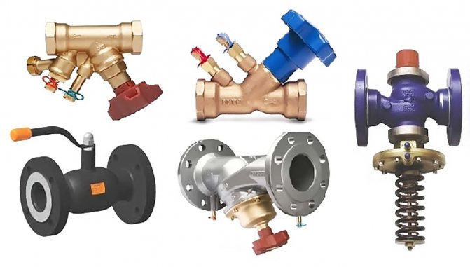
Due to their design features, control valves are very similar to shut-off valves. Therefore, these elements often have the same brand name. Regulating devices are divided into 2 types:
- reducing, which works to reduce the pressure of the working medium;
- shut-off and regulating.
Now about the types of control valves. The most common type is considered to be control valves, which are also divided into several subspecies:
- checkpoints;
- corner;
- mixing, with a three-way design.
The remaining types of control devices include shut-off and control valves, direct-acting pressure regulators, and level regulators.
All of these devices are described in more detail below.
Drain and safety valves.
Safety and drain valves devices for automatically reducing pressure in closed vessels when it reaches a dangerous limit. These valves are used in a wide variety of technical devices from coffee makers, pressure pots and boiler heating systems to power plants, where pressures reach 30 MPa, and power hydraulic systems, where pressures can reach 70 MPa. There is a certain difference between safety and drain valves. The safety valve is a special type of spring-type drain valve that is designed to open momentarily in order to release a large amount of steam or gas at once and then close again abruptly. Drain valves are used to communicate with the atmosphere in liquid systems, and relief valves in high pressure gas and steam systems.
The drain valve opens slightly when the pressure in the vessel reaches a set (low) value, and slowly increases the release of fluid as the pressure rises. The drain valve is usually used where it is undesirable or not necessary to release large volumes of the working fluid.
Features of the operation of control valves
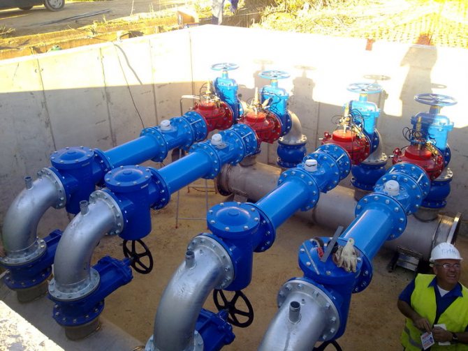
Control valves, as mentioned earlier, are among the most common types of shut-off devices. Their main function is to change the pressure of the medium that passes through a certain pipeline system. Scope of these devices:
- plumbing systems;
- gas supply systems;
- highways designed to move petroleum products and gaseous substances.
The material used for the manufacture of these fittings can be varied: brass, cast iron, steel, high-alloy alloys. The choice of a particular version depends on the piping system and the environment in it.
All control valves are divided into 2 types depending on the characteristics of their work:
- with a manual drive, where control is carried out using a specially built-in handwheel, which, if necessary, must be rotated with your own hands. For pipes with large parameters, this option is practically not used, since bringing the regulating device into operation requires significant efforts;
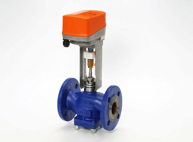
- with automatic control, where the work is carried out due to the built-in hydraulic, pneumatic or electric drive. To ensure the timely operation of the shutter, the regulating device includes sensors that measure the existing pressure in the system.
There is also a classification of control valves depending on their shape:
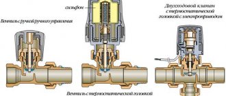
- checkpoints are installed on a straight pipeline and do not affect the direction of the medium in any way;
- angular changes the direction of the medium, and hence the pipeline itself by 90˚;
- mixing pipes include in their design 3 branch pipes, which are two working media in a joint flow.
Features and Benefits
- Simplicity of design.
- Exceptionally low pressure loss at high flow rates.
- Accuracy of regulation at low flow rates for all diameters.
- Suitable for all natural liquids, sea water, industrial effluents.
- Wide range of materials, coatings and diaphragm types.
- All valve models can be used for a variety of control functions when using Dorot Pilot Regulators.
- low sensitivity to defects in the seal area (the diaphragm is flexible and compensates for these defects).
- The diaphragm is not directed and therefore cannot remain open or jam in any position.
- An integrated filter with automatic flushing in the control line eliminates the need for external filters.
- Valve sizes from 20 to 700 mm, working pressure from 0.2 to 25 AT.
- All models are GOST-R certified.
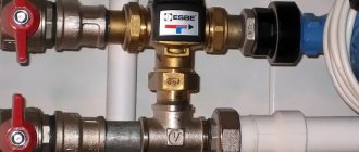
The principle of operation of shut-off and control valves
The main purpose of stop-control valves is to control the working medium in the pipeline and change its flow rate. This control valve can be used in the following systems:
- heating and hot water supply networks;
- central and individual heating points;
- ventilation system.
For each of the conditions, there is a certain type of performance and the material used.
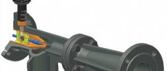
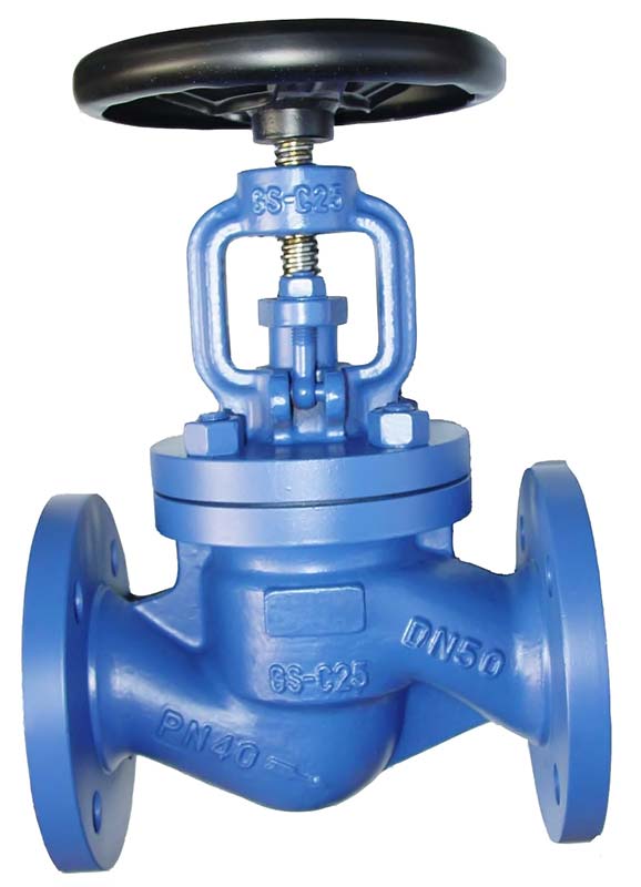
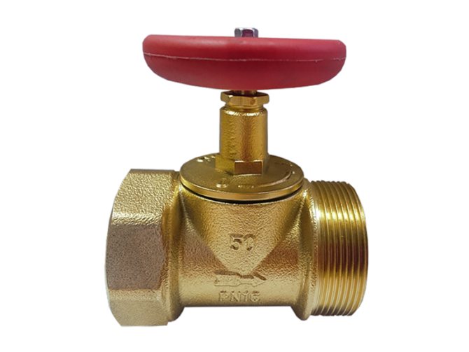
Globe valves are universal control devices. This is due to the fact that they not only control the flow rate of the medium used in the pipeline, but also perform a shut-off function that can completely shut off the flow.
Let us consider the principle of operation of shut-off and control valves: inside the body, the shut-off element moves due to the rotation of the stem, which is set in motion with its own hand or with the help of the provided drive. A feature of this regulating device is the presence of a seal, due to which, when the stem is lowered, the system is completely sealed.
Shut-off and control valves have a number of advantages, the most important of which are ease of use and maintenance, reliability in operation. Installation of regulating devices is possible not only on standard pipelines, but also on highways with non-standard angles and bends. In addition, they are often used to work in aggressive environments.
Valve design and principle of operation
The principle of operation of a shut-off valve is to literally "cut off" the further passage of the contents of the pipes in emergency situations. This unit is designed in such a way as to be instantly triggered when exposed to operating personnel or in automatic mode.
The best example of this type of isolation valve design is the disposable isolation valve. The device of such a unit provides for the presence of four main components:
- the top of the valve, equipped with a special "seat" for the installation of a shut-off device;
- a system of approaches in the lateral parts of the unit for fast fluid flow;
- central valve part;
- base element with moisture-wicking pad to prevent leaks and condensation.
Such a simple and at the same time reliable design allows you to effectively shut off the flow of content in pipes. The priority areas of use of shut-off valves are filtration and water purification systems. Frequent emergencies in these circuits have become the main impetus for the development of valves of this type.
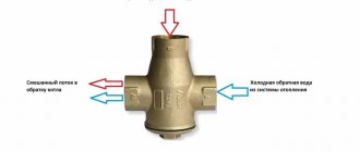
Direct acting pressure regulators
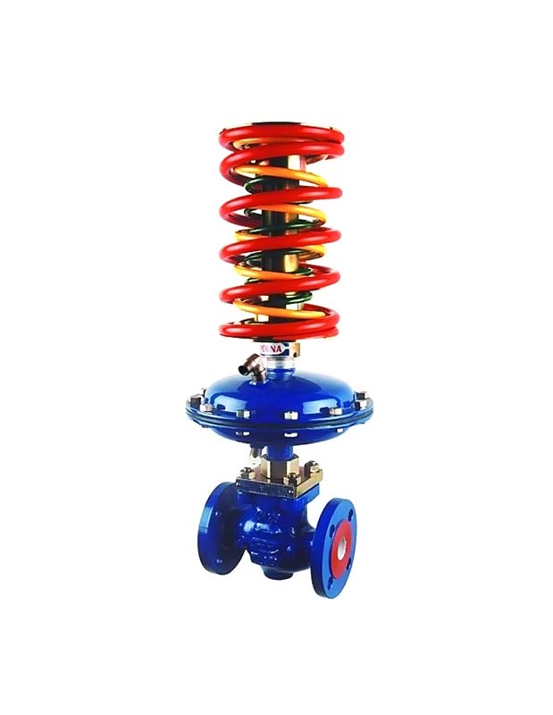
A direct-acting pressure regulator is required to automatically maintain the required differential pressure in one of the sections of the system.
This control valve is divided into 2 types:
- to yourself;
- after myself.
The pressure regulator consists of a body, a double-seat valve, a cover complete with a stuffing box, a load mechanism and a diaphragm-type actuator.
A design feature of such control valves is the presence of two valves at once on one stem. This feature is necessary to balance the pressure indicator of the working medium on the valve, and, accordingly, on the stem.
Both types of regulators differ from each other only in the location of the valves relative to the seats. The control valves "after themselves" under the influence of pressure from the load mechanism, thanks to the valves, forms a passage in the seats. The essence of the operation of this regulating device is quite simple: when the working medium enters it, the flow area is in the open state, so it passes through it into the pipeline. There, an increase in the pressure indicator occurs, which moves along the impulse tube to the membrane and creates a load for the stem in the opposite direction from the effect of the load placed on the lever. Upon reaching a force greater than the force of the load, the movement of the stem will be directed downward and the valves will close the holes in the body.
When adjusting such a control valve to a certain pressure indicator, it is necessary to select the size of the load and its location on the lever.
The difference between the principle of operation of the control valves "to themselves" from the previous type in closed valves under the influence of the existing load. When the pressure in the system increases, then when it is transmitted through the impulse tube to the diaphragm, and thereby a force is created on the rod in the direction opposite to the action of the load. This leads to the opening of the valves, which subsequently leads to the withdrawal of the working medium behind them. This means that the pressure in the system begins to decrease.
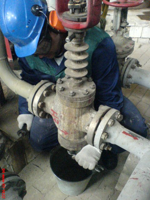
Repair of control and shut-off valves
Repair of control and shut-off valves is performed only after they have been removed from the process pipeline. Small repair of the valve on site is allowed, these are:
- Gland packing;
- Removing the valve covers to check the internal elements of the regulator.
Registration of an order - a permit for repair, gas hazardous work, shutdown of control valves with shut-off valves, release of residual pressure on a disconnected section of the pipeline, as well as preparation (flushing, steaming) of the valve for repair is carried out by technological personnel. Dismantling and installation of the valve for repairs is performed by the service of the chief mechanic.
Do not loosen or tighten the gland packing nut on a control valve that is not shut off.
Carrying out loading and unloading operations in accordance with the requirements of industrial safety and labor protection rules.
Loading and unloading operations should be carried out under the guidance of a foreman or a specially appointed responsible experienced worker.
Before starting work, you must:
- put on overalls, special footwear and other PPE;
- inspect the place of work, lighting, etc .;
- report the noticed dangers to the foreman or the person in charge.
The workplace should not contain people with restrictions on the movement of heavy objects. The maximum permissible weight of the load when alternating lifting and moving with other work should not exceed:
- for women -10 kg;
- for men - 50 kg.
When moving weights over 50 kg, work must be done mechanically (winch, telpher, beam crane, loader, manipulator crane, hoist (tower)).To perform slinging operations (strapping, hooking, securing, hanging on the machine hook, setting in the design position and uncoupling) cargo during the production of work with lifting machines, specially trained skilled workers are allowed - slingers who have a certificate for the right to carry out these works.
Malfunction of pneumatic actuators with spring diaphragm actuators.
1. With a smooth change in the pressure of compressed air in the membrane cavity of the actuator, the stem and the shutter of the single-seat or double-seat regulating body move in jerks.
| Possible reasons | Troubleshooting methods |
| Stem deceleration in the stuffing box of the regulating body due to lack of lubrication or impermissibly high gland tightening | Apply lubricant to the stuffing box device using a lubricator, and if this does not lead to the desired results, then carefully loosen the stuffing box nut, making sure that no leaking substance penetrates through the stuffing box. |
2. A flowing substance (liquid, steam, gas) penetrates through the stuffing box.
| Possible reasons | Troubleshooting methods |
| Insufficient lubrication, loose packing, poor packing quality | Add grease, tighten the stuffing box nut, change the stuffing box nut, change the stuffing box packing |
3. When the pressure of compressed air in the diaphragm cavity of the actuator changes from the minimum to the maximum value, the stem and shutter of the single-seat or double-seat regulating body do not move completely from one extreme position to another.
| Possible reasons | Troubleshooting methods |
| The spring of the diaphragm actuator was compressed more than it should be during adjustment, and therefore, to overcome the forces developed by it, an increased air pressure is required compared to that necessary with a standard spring tension | Gradually loosen the spring tension to a value that ensures the movement of the stem and the valve from one extreme position to another when the air pressure in the membrane cavity of the actuator changes from the minimum to the maximum normalized values |
| The spring of the diaphragm actuator is not sufficiently compressed during adjustment and cannot overcome the friction forces arising in the moving part of the actuator, as well as the mass of this part and the forces from the pressure of the flowing substance on the valve (therefore, the valve does not rise completely) | Gradually increase the spring tension to a value that allows the shutter to move from one extreme position to another when the air pressure in the membrane cavity changes from the minimum to the maximum normalized values |
| During its stroke, the shutter rests against a foreign object that has fallen into the membrane actuator (coke, sand, metal gasket, nut, etc.) | Disconnect the compressed air line from the diaphragm chamber of the actuator by switching the flow to the bypass line, and take measures to clean the body of the diaphragm actuator from foreign objects. Ensure that the surfaces of the valve and seats are not damaged |
4. When compressed air is supplied to the diaphragm cavity of the actuator, the stem does not move.
| Possible reasons | Troubleshooting methods |
| Damage to the diaphragm due to exceeding the compressed air pressure of the limit value or due to the ingress of oil, gasoline or other petroleum products on the diaphragm (together with air or otherwise), which destructively affects the diaphragm material | Disassemble the diaphragm actuator and replace the defective diaphragm with a serviceable one. In this case, the thickness and number of fabric rubber layers should be selected the same with the one that is removed |
five.When regulating the flow rate of the flowing substance, the shutter of the diaphragm actuator most often takes a position close to one of the extreme.
| Possible reasons | Troubleshooting methods |
| If, during normal operation of the regulator, the valve almost closes the seat opening or, conversely, opens it almost completely and at the same time the pressure in the membrane cavity is close to the limit, this indicates that the nominal diameter of the diaphragm actuator is either large or small for this pipeline and consumption in it | In accordance with the actual flow rate of the medium flowing through the pipeline, select the appropriate nominal size of the diaphragm actuator and, if there is a diaphragm actuator with this nominal size, install it. If a suitable actuator is not available and it is possible to grind a new valve, then calculate the profile of the new valve and replace the old valve with a new one in the diaphragm actuator. |
Actuators
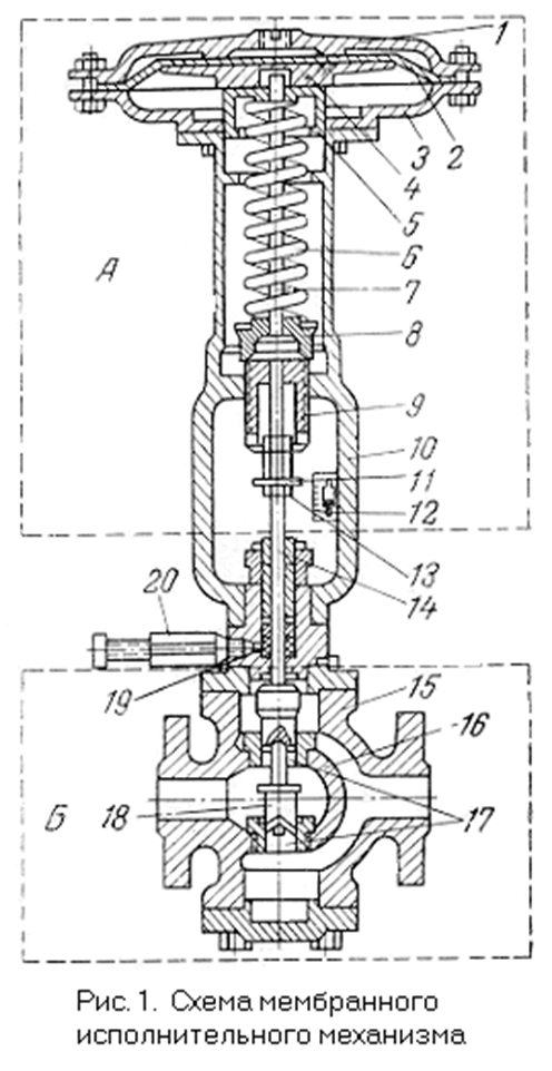
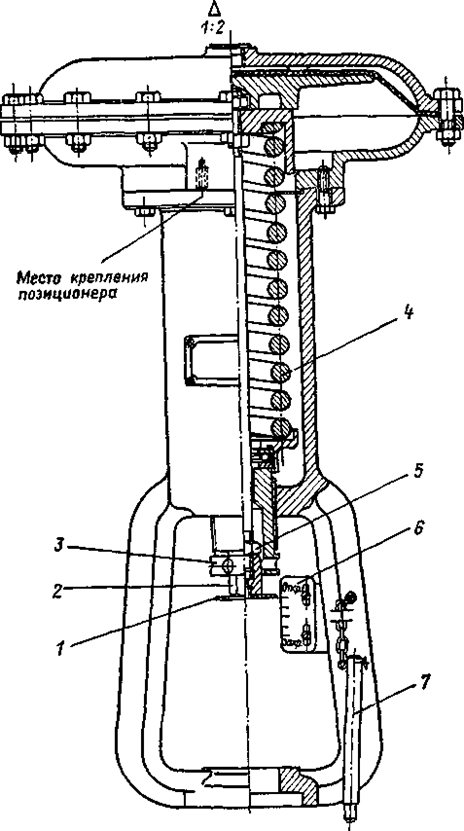
Actuator A consists of:
1 - upper cover, 2 - elastic membrane made of dense rubberized fabric, 3 - lower cover, 4 - metal disc, 5 - guide cup, 6 - springs, 7 - stem, 8 - support, 9 - nut, 10 - bracket, 11 - disc, 12 - scale, 13 - connecting nut, 14 - stem,
Regulatory Authority B includes:
15 - body, 16 - baffle, 17 - with cylindrical holes, 18 - valve, 19 - oil seal, 20 - lubricator
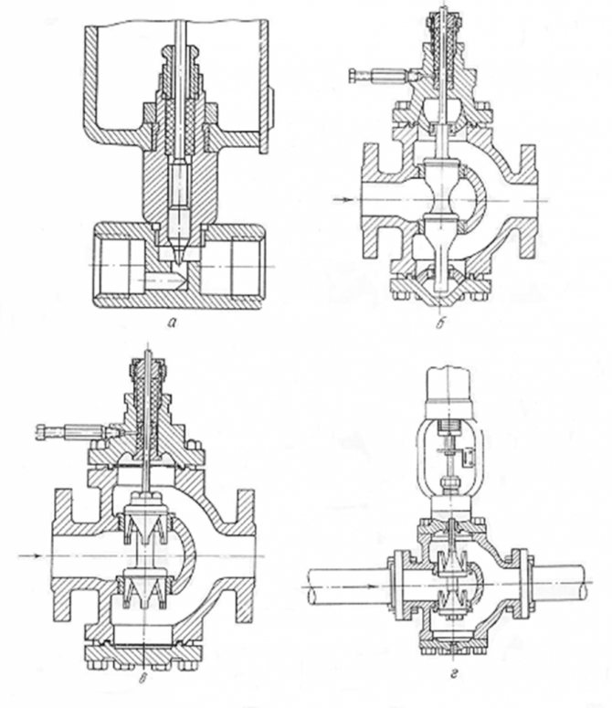
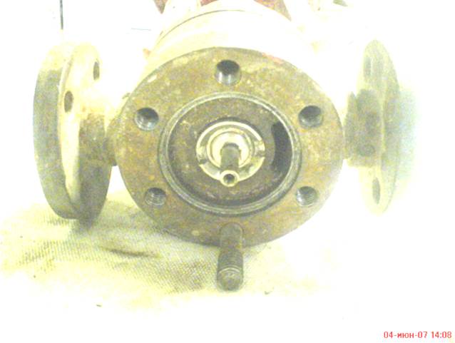
Usually, the regulating bodies of the actuators installed in large-diameter pipelines are double-seated (see Fig. B, c, d) to reduce the forces on the valve from the medium at large pressure drops. Single-seat regulating bodies are used for installation in pipelines of small diameter and with small pressure drops across the valve (see fig.a)
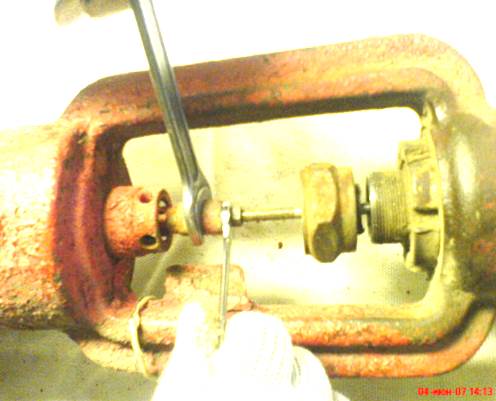
Disassembly and assembly of the control valve.
Disassembly of diaphragm actuators.
Disassembly of a normally open actuator is carried out to identify the condition of individual parts, cleaning and repair as follows.
All visible surfaces of the actuator (housing, diaphragm actuator, etc.) are blown off with compressed air from a hose and thoroughly cleaned of dirt.
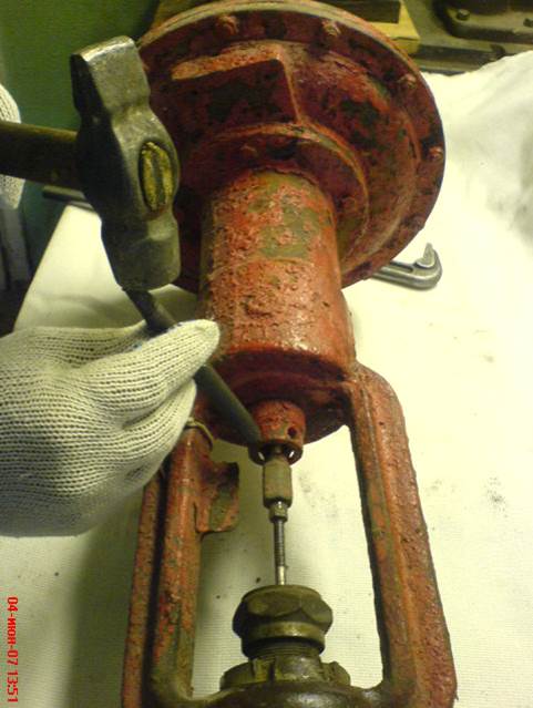
By rotating the lock nut 5 (Fig. 1), a special nut 2 is released, after which, by rotating this nut, the plunger rod is disconnected from the intermediate rod. If the actuator has a pneumatic positioner, the lever is released to allow the diaphragm actuator to separate from the regulating body. Unscrew a special nut 11 (Fig. 2) and separate the diaphragm actuator from the body of the regulating body.
Picture 1.
Repair of membrane actuators.
In this case, large mechanisms are lifted with hoists or winches. Free the valve stem from the nuts. Check manually the ease of movement of the shutter to the extreme positions.
Disassembly of the control valve actuator.
Carefully unscrew the nuts of the studs or bolts on the top cover 4 (Figure 2) so as not to overload individual fasteners and reduce their reliability. This work is carried out in two steps: first, by the method of diametrically opposite bypass, all the nuts are turned by 1/8 of their full turn, and then all the nuts are unscrewed in any order. After reducing the oil pressure in the stuffing box, remove the lubricator (oiler). The position of the cover on the body is marked for installation in the future to its original place. Carefully, so as not to damage the stem and the shutter, separate the top cover 4 from the body 3. If the cover is heavy, then lifting it is carried out with hoists or a winch. When lifting, follow the strictly vertical movements of the cover.
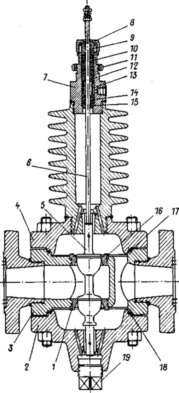
Figure 2.
Remove the shutter 5 with the stem 6 and thoroughly clean their surface from dirt and remnants of the stuffing box packing. In this case, it is forbidden to use a sharp metal tool (chisel, knife, awl, etc.) in order to avoid damage to the surfaces to be cleaned. Unscrew the union nut 8 and remove the packing follower 9, rings 15 and 12, bushing 13 and remnants of stuffing box packing 14 and 10. The stuffing box, packing box, rings and bushing are thoroughly cleaned of packing traces without using sharp metal tools.
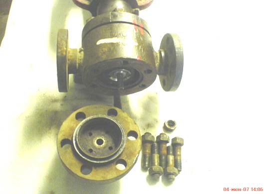
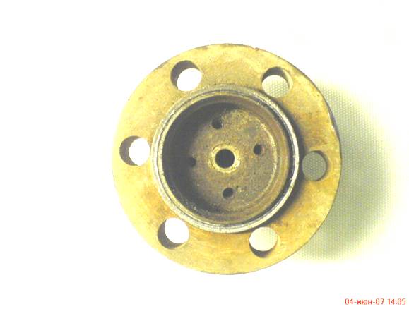
Mark the position of the bottom cover 2 relative to the body. Unscrew the nuts on the studs or bolts and separate the bottom cover 2 from the valve body 3. Unscrew the plug 19. Flush and clean the body and covers. Having finished cleaning the bottom cover, screw the plug 19. Rinse and clean the seats 1 and 16 from layers and, if necessary, replace or repair them, turn them out of the body.
In normally closed actuators, first the bottom cover is removed, and then the shutter with the stem is removed through the hole formed.
When disassembling the diaphragm actuators, which are structurally different from the described design, take into account the bolting of the diaphragm actuator to the cover of the regulating body, the connection of the rods by means of a threaded bushing with locking screws and the fastening of the rod to the valve by means of a split head.
Assembling the control valve actuator.
A normally open actuator with a pneumatic positioner is assembled as follows (designations are shown in Fig. 2).
1. Seats 1 and 16 are screwed into the body 3 of the regulating body. In this case, the use of chisels, guides, etc. is not allowed. tools and seating the saddle in the sockets on red lead or graphite with oil. The seats are screwed in with special keys or devices. The seat must be screwed in forcefully, i.e. there should be a tight fit with slight interference; wobbling of the seat when screwing in is not allowed. When the nominal bore of the regulating body is Dy = 20 mm, the saddle is screwed in by two workers using a lever with a length of 220 mm. At the same time, they create a torque of 151 Nm (1540 kgf / cm2) with a force on the lever of 700 N (70 kgf).
With a nominal bore of the regulating body Dy = 50 mm, two workers, using a lever 1300 mm long, when screwing in the saddle, create a torque of 892 Nm (9100 kgf / cm2) with a force on the lever of 700 N (70 kgf). With a nominal bore Dy = 100 mm, screwing in the saddle requires the action of four workers, using a lever with a length of 2500 mm and creating a torque of 2432 Nm (35,000 kgf / cm2) with a force on the wrench lever of 1.4 kN (140 kgf).
When screwing in tightly, the saddle may deform. The absence of deformation is determined by means of a control plate. The deformed saddle is replaced. Installing different gaskets between the body of the regulator body and the seat does not give positive results.
2. An aluminum or steel gasket 18 with a thickness of 2 mm is installed under the bottom cover 2, after which the bottom cover is placed in its place, aligning the marks on the cover and body previously applied during disassembly of the regulating body, and the cover is fixed with nuts on studs or bolts. An aluminum gasket is used if the regulator does not have a ribbed jacket, i.e. will work at a temperature of the working environment not higher than 200 ° C, and a steel gasket is installed if the regulating body has a ribbed jacket, i.e., it is designed to work at a temperature of the flowing substance above 200 ° C, for example, up to 450 ° C.
Instead of aluminum or steel gaskets, it is possible to use paronite or klingerite gaskets with a thickness of 2 mm, but they are less reliable than aluminum or steel gaskets, due to the small width of the annular surface of the gaskets.It is not allowed to use paronite or klingerite gaskets with traces of fractures, wrinkles and cracks. Slight hairiness is allowed on the surface and edges.
When bent by 180 ° around a rod with a diameter of 42 mm, the gaskets must not break, crack or delaminate. Tightening nuts on studs or bolts is first done with a normal wrench without a lever, with tightening the studs or bolts in a diametrical position. After the circular tightening of the studs or bolts with a wrench of normal length, levers are used, observing the rule of crosswise bypassing the nuts. When fastening the nuts tightly, blows with a sledgehammer on the key are not allowed. In this case, elongated wrenches are used or tubes are put on short wrenches to lengthen the handle. Nuts on studs or bolts with a diameter of up to 16 mm should be tightened by one worker, using a lever with a length of 500 mm, on studs or bolts with a diameter of 17 to 25 mm - two workers, using a lever with a length of 1000 mm, on studs or bolts from 26 to 48 mm - three workers using a 1500 mm arm. The cover is considered to be fixed after three times tightening the nuts on all studs (bolts) with a wrench with a lever.
3. Having installed the body of the regulating body with the lower cover on a vise, if the dimensions of the body allow, or with the position of these parts on the floor of the room, if the regulating body is large in size, lapping the seating surfaces of the plunger and seats is performed as follows. Flush the seating surfaces of the plug and seats with gasoline and wipe dry. Lapping is done, for example, with a mixture of emery powder and machine oil. Emery powder is obtained by selecting with a magnet the metal part of the dust remaining when sharpening the cutters on the emery wheels. The layer applied to the lapped surfaces should be uniform and not too thick. After six-seven-fold rotation of the plunger by hand in an arc to the right and left by 1/4 of the circle, the plunger is slightly raised and, having turned 180 ° clockwise, is again lowered onto the seat and the grinding operation is repeated.
Repositioning the plunger is repeated five times, after which the lapped surfaces are washed with gasoline and wiped dry. The grinding is repeated using micropowders (from M-28 to M-7), after which the finishing is carried out with the GOI paste (State Optical Institute named after S.I. Vavilov). GOI paste is produced for rough finishing - black, for medium - dark green and thin - light green. Before applying the paste, the lapped surfaces are moistened with kerosene. During final finishing, the layer of paste applied to the surfaces of the seats and valve should be minimal. With a good lapping, the surfaces should be exactly the same "for a shine", without glare, streaks, etc. The shutter should stick to the seats in the body when lifting. The task of lapping is to ensure a tight and simultaneous fit of the valve onto the seats in the body. The entire process of lapping the valve and the seats is carried out, trying not to create additional valve pressure on the seats, except for the mass of the valve itself.
4. Screw the stem 6 into the valve 5 (Fig. 2) and lock it with a pin, after which the valve with the stem is installed in place, ie, on the seats. The fastening nuts are removed from the stem (Fig. 3).
5. Install the upper aluminum or steel gasket 17 with a thickness of 2 mm, then carefully place the top cover 4 in its place, aligning the marks on the cover and body, made earlier when disassembling the regulator, and fix the cover with nuts on studs or bolts. The nuts are tightened using the method specified in the description of the installation of the bottom cover.
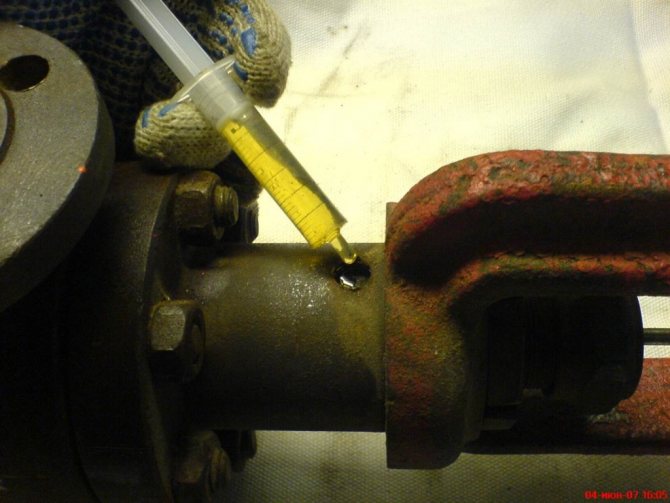
6. Install the lower replaceable metal gland ring 15, then the gland packing rings 14 and the stuffing box sleeve ("lantern") 13. The stuffing box rings are fed into the cover sleeve 7 with a piece of tube having an inner diameter sufficient to fit it onto valve stem.Above the lower replaceable ring 15, the thickness of the stuffing box packing 14 should be such that the lower holes of the sleeve 13 are located opposite the hole for the lubricator (oiler). Install the lubricator and fill it and the sleeve 13 with grease.
Figure 3.
Grease for steel valves - ossogolin grade 300-AAA; for cast iron valves - NK-50 grease. Then the upper replaceable metal ring 12 is installed, several rings of the stuffing box packing 10, to the packing follower 9. The thickness of the packing above the upper replaceable ring 12 should be such that the packing follower 9, after its installation, protrudes from the sleeve 7 of the upper cover by 80% of its height.
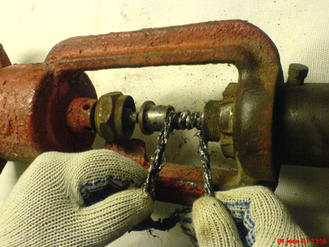
This allows the packing follower to move downward when the packing is tightened. For steel regulating bodies, stuffing rings made of pressed asbestos are used, and for cast iron ones, an asbestos cord impregnated with a special compound. In the latter case, an asbestos cord is taken and boiled in the following composition: 18% graphite, 11% rubber glue, 5% grease 66% petroleum jelly. To prepare the rubber glue, 200 g of unvulcanized rubber is dissolved by heating in 250 g of vaseline oil. The composition is prepared as follows: petroleum jelly and grease are melted in a water bath, after which the solution is removed from the bath and rubber glue is poured into it with vigorous stirring, and then graphite is poured in portions with vigorous stirring until it thickens, as a result of which the solution is considered ready.
The preparation of rings from a cord is carried out by winding the cord on a rod having the same diameter as the rod, and cutting the cord at an angle (oblique cutting), as shown in Fig. 4. The prepared rings are pressed each separately in a device, which is a copy of the stuffing box of the regulating body, and then stored in closed boxes to avoid contamination. When laid in the gland, the ring joint is made with an overlap, with cuts at 45 °. The joints of individual rings are shifted relative to each other by 90 ° in accordance with GOST 5152-84. Put on the union nut 8 and, rotating it by hand without the help of a wrench, tighten the gland. The gland tightening is considered normal when the stem, being previously raised by hand and then released, gradually lowers under its own weight. With increasing pressure, it becomes necessary to tighten the gland more significantly. The required seal tightness is achieved by increasing the lubricant pressure from the lubricator. The diaphragm actuator is installed on the regulating body and secured with a special nut 11 (Fig. 2).
Figure 4. Preparation of gland packing rings
1 - stuffing box cord; 2 - rod; 3 - cut line.
9. Screw the nut onto the stem, then lock it with the second nut. Put the lever from the positioner onto the stem, then the pointer 1 (Fig. 1), after which a special nut 2 is screwed onto the stem, which connects the valve stem to the intermediate stem. By means of the nut 5, the position of the nut 2 is fixed. If the pointer / turns out to be displaced relative to the scale 6 of the position of the shutter, then move the latter so that the inscription "Open" is opposite the pointer.
The positioner is fixed on the body of the diaphragm actuator and the lever is connected to the rod, after which the assembled actuator is supplied for adjustment.
The assembly of a normally closed actuator differs from the described assembly in that the positions of the seats and the valve are respectively changed, and after installing the upper cover, without installing the lower cover, the valve and the seats are lapped. Subsequently, the position of the scale is changed by turning it by 180 °.
When adjusting, compressed air pressure is supplied to the diaphragm cavity and, by changing the tension of the spring 4, a full stroke of the valve is achieved when the pressure changes from a minimum to a maximum value.The adjustment is carried out with the key 7, rotating the threaded bushing 3. At a pressure equal to 50% of the maximum pressure in the diaphragm cavity of the actuator, the upper lever of the positioner must be parallel to the lever attached to the valve stem. Otherwise, adjust the length of the vertical rod attached by the lower end to the specified lever and transmitting its movement to the positioner mechanism.
The assembly of diaphragm actuators of a different design is carried out in the same sequence as above, but taking into account the design features of these actuators, namely: bolting the diaphragm actuator to the upper cover of the regulating body, connecting the rods by means of a threaded bushing with locking screws and fastening stem to the valve by means of a split head, another design of the connection between the positioner and the valve stem. When assembling, 2 mm thick paronite gaskets are installed under the upper and lower covers of the regulating body and 1 mm thick under the valve head cap. In the absence of bolt position indicators, a scale plate is fixed on the bracket by means of a clamp, an indicator is placed under the threaded bushing.
Conversion of a normally open actuator to a normally closed one.
A normally open actuator differs from a normally closed only in the arrangement of the seats, plug and scale plate. In fig. 2 shows a normally open actuator. To convert this device into a normally closed one, guided by the described procedure for disassembling and assembling these devices, the upper 4 and lower 2 covers are separated; removing the pin, unscrew the rod 6 from the bolt 5 and then, screwing the rod 6 into the opposite end of the bolt 5, fix this position with a pin; the saddles I and 16 are unscrewed and replaced, that is, the saddle 1 is screwed into the place of the saddle 16 and, conversely, the saddle 16 is screwed into the place previously occupied by the saddle 1; install the valve by passing the stem from the bottom through the holes in the seats; assemble the executive device; the scale plate is installed so that at the top there is an inscription "Closed", and at the bottom - an inscription "Open".
Alteration of a normally closed actuator into a normally open one is reduced to the same operations, but the scale plate is set in a position in which the inscription "Open" is in the upper part of it, and the inscription "Closed" is in the lower part.
Alteration of actuators of some structures from normally closed to normally open or vice versa, due to the inability of the valve for this purpose, is carried out in the presence of a spare valve with a correspondingly located connecting diaphragm cavity (Fig. 5).
Figure 5. Hollow plug of a two-seat regulating body of a normally closed actuator
Repair of housings and covers of executive devices.
To identify the need to repair the bodies and covers of the actuators, they are first carefully examined, especially in the areas of abrupt transition of sections, near the ribs and the transition of the body to the flange, and then a hydraulic test of the body and covers for strength is performed.
The strength test is carried out with a hydraulic press at a test pressure Pi = 2.4 MPa (24 kgf / cm2) for executive devices with PN = 1.6 MPa (16 kgf / cm2), Pi = 6 MPa (60 kgf / cm2) for executive devices. devices with PN = 4 MPa (40 kgf / cm2) and at test pressure Pi = 9.6 MPa (96 kgf / cm2) for actuators with PN = 6.4 MPa (64 kgf / cm2). During testing, it is advisable to fill the press with kerosene or oil, since water filling of the press leads to the appearance of rust in defective places. Revealed cracks, through and deep cavities in housings and covers are repaired by electric arc welding.Places for welding are cut with a pneumatic or manual cutting tool (chisel, file, drill, etc.). Smelting of a defective spot by autogen is not recommended in order to avoid a weakening of the strength of the metal due to carbon burnout during smelting.
When repairing cast-iron housings and covers, cold welding is used with OZCH-4 electrodes. The thickness of the coating should be 1.0 - 1.2 mm with a rod diameter of 3 mm, i.e. after coating, the electrode diameter will be 5.0 - 5.4 mm; 1.25 - 1.40 mm - with a rod diameter of 4 mm and 1.5 - 1.7 mm - with a 5 mm rod diameter. The ratio of the coating mass to the rod mass for all electrode diameters is approximately 35%.
Cast iron deposited with such an electrode lends itself to machining with a carbide cutting tool. Welding is carried out in sections. Each section for stress relief and sealing of the weld metal is subjected to forging by hand with a hammer immediately after welding. The seams are performed in at least two passes. Cracks are welded in a reverse-step manner.
Welding is carried out on direct current with reverse polarity. The welding current is approximately 25 - 30 A per 1 mm of the electrode diameter. Welding is carried out with short seams (about 30 mm) with air cooling to 60 ° C.
When repairing bodies, the condition of the thread in the body for screwing in the seats is determined: the cleanliness of the processing and the tightness of the seat are checked. The thread should not have burrs, chipped threads, dents, etc., as well as traces of wear by the working substance. The thread must be clean, ground and grade 2. The tightness of the thread is checked when unscrewing and screwing in the seats, which must be unscrewed or screwed in with some effort (tight fit).
When repairing housings, the condition of the thread for the studs is determined. If the thread is worn out and the wall thickness between the studs is sufficient, then a new thread of a slightly larger size is cut and a stud is made for this size. If the wall thickness is small, then a cylinder is pressed into the hole for the hairpin and, having welded it on both sides, a hole is drilled in it and the thread is cut for the hairpin.
Turning out defective pins is sometimes difficult, especially for pins, some of which are broken off. In the latter case, a hole is drilled in the hairpin to a depth of 10 - 15 mm and made square, after which a square rod is inserted and the hairpin is unscrewed from the body with a key. Sometimes a rod is welded to the stud and then twisted out.
Repair of saddles and valves.
The wear of the seat and valve seating surfaces is influenced by two factors: corrosion and erosion.
Corrosion manifests itself in the destruction of the surfaces of these parts under the action of a flowing substance that chemically interacts with the materials from which the parts are made. The degree of destruction can be reduced by appropriate selection of materials used for the manufacture of seats and valve.
Erosion manifests itself in the destruction of the surfaces of the seats and the shutter due to the abrasive effect of the working substance. Erosion is especially manifested in conditions when the valve is still a little open, since a narrow annular passage is formed between the seats and the valve and the abrasive effect of the working substance increases. Erosive wear also occurs with the wrong choice of material for the manufacture of seats and a shutter or non-observance of the modes of their heat treatment.
As a result of the processes of corrosion and erosion, the configuration of the seats and the gate of the actuator changes, which violates the characteristics of the latter. In addition, an impermissible passage of the flowing medium occurs when the actuator is completely closed. One-sided destruction of the working surface of the seats leads to a curvature of the stem and an increase in the friction of the valve in the support guide bushings, which first causes an increase in the dead zone, and then - a complete cessation of valve movements.
To restore the worn out sealing surfaces of the seats and the gate, surfacing with alloy electrodes is used, which reduces the consumption of scarce alloy steels.It is advisable to weld the seats and gates of valves operating at a high temperature of the flowing substance with electrodes intended for arc welding with high-alloy steels with special properties. The coating should be thick or extra thick.
Release from repair of executive devices.
External examination before testing.
Purpose: to establish the suitability of the repaired actuator for further testing for release from repair.
Requirements: the color of the color of the body of the regulating body and the actuator must correspond to the materials used for the manufacture of these parts (bodies made of carbon steel - gray, from alloyed acid-resistant and stainless steels - blue, from cast iron - black; membrane actuators - orange or black color, etc.); the color of the body of the regulating body and the actuator should not have defects that worsen the appearance of the valve; for all parts with a thread, the latter must not have defective threads, must be clean, without burrs; all screws, bolts, nuts, studs, and other parts included with the regulator must be present.
Tightness test of regulating bodies in seats and gaskets.
The test of the regulating bodies for tightness in the seats and gaskets is carried out by hydraulic presses filled with kerosene or oil having a viscosity of not more than 2 ° E. When testing the regulating body for tightness in the gaskets and the gland, kerosene or oil is supplied through the hole in the outlet flange, and the hole in the inlet flange is closed ... The test is carried out under a pressure equal to the nominal pressure.
When testing the regulating body for the tightness of the valve in the seats, kerosene or oil is supplied through the opening of the inlet flange, and the opening of the outlet flange is closed. In this case, the test pressure for all types of regulatory bodies should be 1 MPa (10 kgf / cm2). From the surface of the first weld bead, slag is knocked down with a hammer and cleaned with a metal brush, both the bead itself and the surface of the saddle or gate to be welded adjacent to the bead. Insufficient removal of slag, metal spatter, etc. will make it difficult to apply the second bead and will lead to porous and uneven surfacing.
Repeating the operations of pp. 3 and 4, a second bead (second layer) is deposited. The total deposition height will be 4 - 6 mm. Surfacing is again carried out in the same direction, while the beginning of the weld is overlapped at a length of 10 - 15 mm. Surfacing is continued until the desired value of the deposited layer is obtained with an allowance for machining of at least 3 mm on each side and 3 - 5 mm in height. On the surface of the deposited layer, a certain number of small pores and cavities with a diameter of not more than 1 mm are allowed, provided that they will be removed during subsequent machining.
The deposited saddle or gate is subjected to heat treatment - tempering at a temperature of '500 - 550 ° C with holding at this temperature for 2 hours, followed by slow cooling (together with a heating furnace).
The welded solid shutter is installed on a lathe and processed under a template, first removing the excess metal with a cutter, then with a personal velvet file, thin glass paper, and polishing with a polishing paste.
The final boring of the deposited saddles is carried out together with the body on a lathe. For this, the seats are screwed into the valve body with an overlap in the thread and until the flat sealing surfaces are tight (near the thread).
When making a new saddle or machining a weld-on saddle on a lathe, an eccentricity of the through-hole (landing) hole and the threaded circumference of the saddle no more than 0.02 mm per 100 mm of the length of the diameter is allowed.
Two templates are needed to reconcile the seat configuration - the upper saddle profile template and the lower saddle profile template. The manufacture of these templates is not difficult, since in essence it is important for the saddle only to maintain the profile of the seating surface, its location and the diameter of the passage. The shape of the profile of the inlet part of the saddle does not really matter. When testing normally open actuators, to close them, air is supplied to the diaphragm cavity under the limiting actuation pressure, and normally closed actuators must be closed by the normal setting tension of the spring.
Regulating actuators designed to operate in gaseous media (steam, air, gases) are subjected to an additional leak test in the stuffing box and gaskets with air pressure supplied from the outlet flange, 1.3 MPa (13 kgf / cm2) - for cast iron regulating bodies, 2.2 MPa (22 kgf / cm2) - for steel regulatory bodies at PN = 4.0 MPa (40 kgf / cm2) and 3.4 MPa (34 kgf / cm2) - for steel regulatory bodies at PN = 6 , 4 MPa (64 kgf / cm2).
Requirements:
the passage of kerosene or oil through the gaskets or the gland during the tightness test is not allowed;
the amount of kerosene or oil passed per minute through the sealing surfaces of the seats, depending on the nominal diameter of the regulating body, should not exceed the following values:
| Diameter of the regulating body Dy, mm | 15 — 25 | 50 — 80 | 100 — 125 | 150 | 200 | 250 — 300 |
| The amount of kerosene or oil, cm3 | 10 | 20 | 30 | 40 | 50 | 75 |
Air leakage through gaskets and stuffing box packing during air pressure testing is not allowed.
Checking the quality of the assembly of the actuator.
The quality check of the assembly of the actuator is performed on the installation shown in Fig. 6.
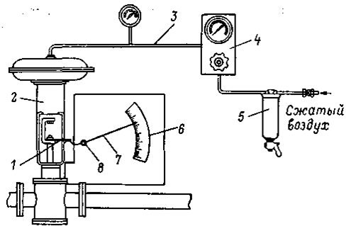
Figure 6.
A plate / is attached to the rod of the tested actuator 2, which, when the shutter moves, acts on the curved end of the arrow 7, which is axially fastened at point 8. The axis 8 of the arrow is fixed on a stationary board temporarily attached to the upper cover of the actuator body. The ratio of the length of the arms of the arrow is taken approximately 15: 1 in order to increase the length of the scale 6. The scale is pre-graduated as a percentage of the stroke of the actuator stem, that is, it is marked in one hundred equal parts.
Compressed air is supplied to the membrane cavity through the filter 5 and the remote control panel 4 through the tube 3, the pressure of which is measured with a standard manometer (the pressure of compressed air in front of the reducer should be 150-200 kPa). By changing the tension of the adjusting spring, they achieve the full stroke of the shutter when the air pressure in the membrane cavity changes within the operating limits.
Level Control Information
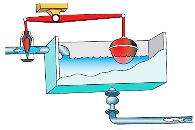
The purpose of the level regulator is to maintain the level of the working medium (liquid) within the required limits and at a given height. The vessel used can be under pressure, or it can be connected directly to the atmosphere, which is much more common. Such conditions are typical for tanks filled with oil products or water. The pressure indicator is maintained at a given level here due to the inlet of an additional volume of liquid. In this case, the control valve is called the power regulator. When fluid is discharged from the reservoir by excess pressure, the control valve is called an overflow regulator.
The active and main elements in such a control valve are a level position sensor, more often called a sensitive element, and an actuating element, presented in the form of a regulating or shut-off valve.
The principle of operation of such a device is based on stopping or regulating the supply of the working medium (liquid) using an actuator, the operation of which depends on the command notification of the built-in sensor.
For direct acting level controls, the sensor is usually a hollow ball float connected to the valve plug. When the water level rises or falls above the set limits, the float creates a lifting force, which moves the valve lever in the direction set for the operation of the regulator actuator.
Disposable valve in operation
It is very important to understand how a disposable shut-off valve works to prevent breakage and leaks in major domestic and industrial pipelines. So, when the liquid flows through the pipes and reaches the check valve, it hits the gasket, which has an absorbent function. Further, the absorbent valve element is filled with moisture and increases in volume, after which the gasket literally cuts off further passage of the liquid, and also prevents it from flowing out.
When using single-use shut-off valves in a domestic environment, it is necessary to monitor the timely maintenance and replacement of devices installed on the pipeline. In any case, with a sufficiently long operation of the valve, which prevents the passage of liquid into the purification or filtration system, it is worth considering its maximum absorption capacity according to the factory instructions.
Taking into account the peculiarities of using a disposable valve as a shut-off valve, the cost of purchasing and installing it is always justified. Emergencies and failures in the operation of water pipelines occur, although not so often, but often have significant negative consequences. Therefore, if the design of the valve is made of high-quality and reliable materials, and its installation is carried out correctly, then more serious consequences can be avoided. Once used, the valve must be replaced, but its cost will always be less than the cost of repair after flooding and even a small water leak.
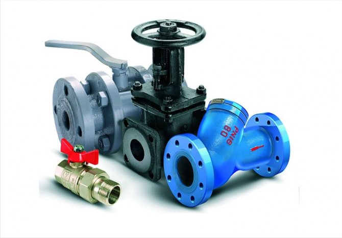
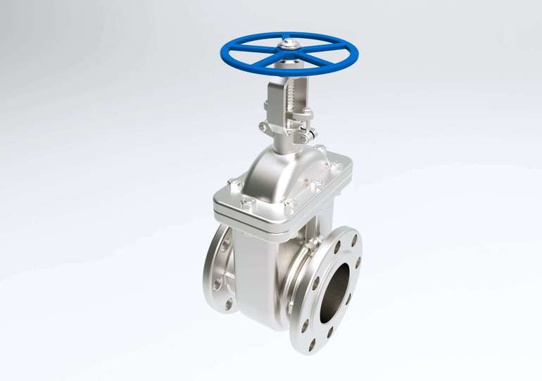
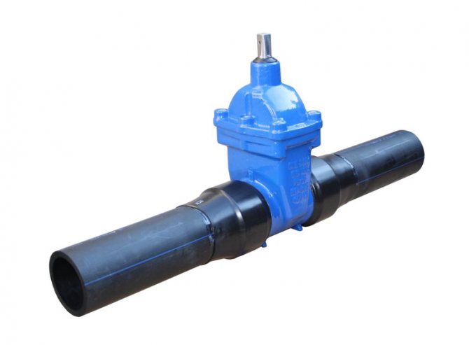
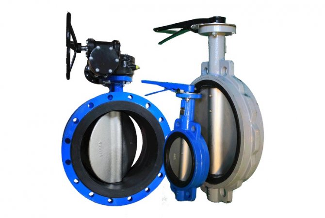
Popular Flanged Valve Models
Today there are several types of shut-off valves. It all depends on what method is used in order to overlap the working environment. The list of popular models includes the following mechanisms:
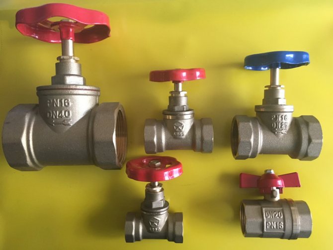
- screw;
- gate;
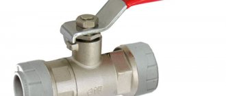
- ball;
- cork.
On screwed parts, the movable valve is fastened with a screw connection. It must be pressed against the seat, which is located in the master cylinder of the valve. The gland packing is represented by a sealing washer, which ensures the tightness of the device.
The specific disadvantages of the mechanism include the fact that it passes water in only one direction, and its rubber or paronite tubes periodically wear out and need to be replaced. If sand or scale enters the cylinder, the gaskets can be completely or partially destroyed.
The gate valves are very similar in design to a gate valve, as their threaded stem facilitates the deflation of the tapered valve between the two mirrors. Instead of stuffing box packing, you can install seals made of rubber or polymer clay, which differ in service life over a long period of time.
For the manufacture of ball flange fittings, brass or stainless steel is used, and the design is a ball with through holes. The rotation of the handle ensures rotation of the ball in the valve cylinder, and its fixation is carried out using a pair of annular seats made of Teflon or fluoroplastic. It is recommended to use the same material for sealing.
Flanged plug valves are closed off by a conical plug fitted with a through hole. Typical problems with these devices are that the packing must be changed periodically.