In heating systems, where heaters and coolers are used in the piping nodes, there is a characteristic type of fittings - a two-way valve. The device quickly and accurately regulates the volumes of water supply and withdrawal. It is in demand in heating, ventilation and air conditioning systems. Nowadays, two-way valves equipped with an electric actuator, which are controlled by special sensors, are in great demand. These are reliable and easy-to-install devices, the design features and differences of which we will learn below.
Two way valve
Purpose and design
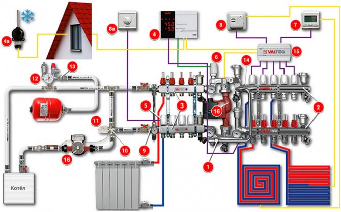
The classic equipment of the device is as follows:
- thermostatic valve;
- thermal head with a remote sensor;
- thermal head valve;
- limiting sensor taking into account temperature;
- meter;
- circulation pump;
- water filter;
- check valve.
Two-way adjustment devices are used everywhere, but a lot depends on what material they are made of. Considering the design features, we will immediately make a reservation that valves are available with one or two seats. Using the second type, the flows of the working medium are regulated and shut off, and significant pressure drops are allowed, which a single-seat valve cannot cope with. The valve itself looks like a separate part with a mechanical or electronic drive. It happens that an additional source of energy is not provided, therefore it is installed after the installation of the device.
Advantages of a two-way valve:
- simple construction;
- easy to install;
- does not require human involvement for effective work;
- maintainable;
- reliable;
- serves for a long time;
- sealed;
- characterized by low hydraulic resistance;
- available.
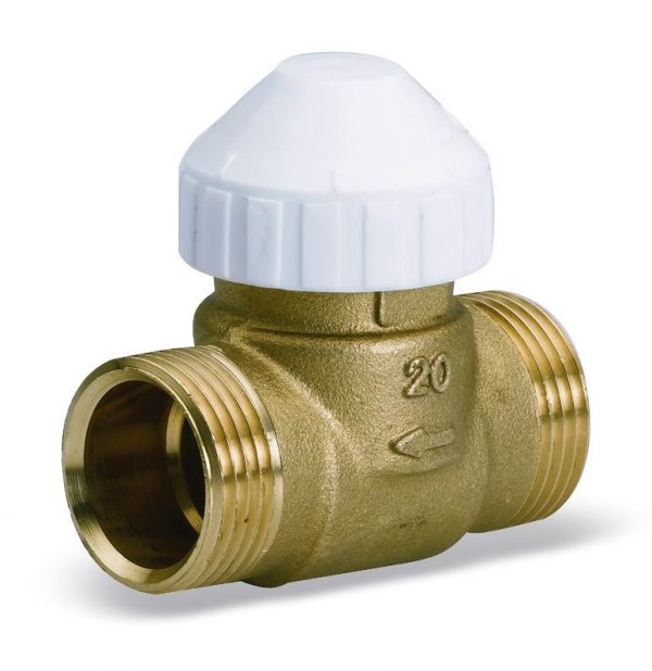
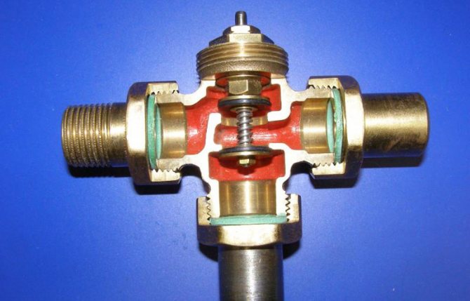
Paying attention to the design of the element, it will seem that it is similar to a standard valve, but the mechanisms are significantly different. For example, the main plug of a valve is a stem or ball. That is, the stem, which is in a horizontal or vertical position, or a ball rotated around its axis by 90 degrees, is responsible for limiting the flow of water. The device works according to a simple scheme - a special hole opens and liquid is transported through it. For these structural elements to function, an actuator is connected to the valve, which requires electricity or compressed air. The drive itself is combined with separate devices that take into account system pressure, temperature and other characteristics.
Valve design
How to choose and apply a three-way valve
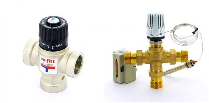
The three-way valve must be correctly selected for its capacity. It must also have the correct thread diameter (1/2 or 3/4 inch) and properly align with the thermal head or servo.
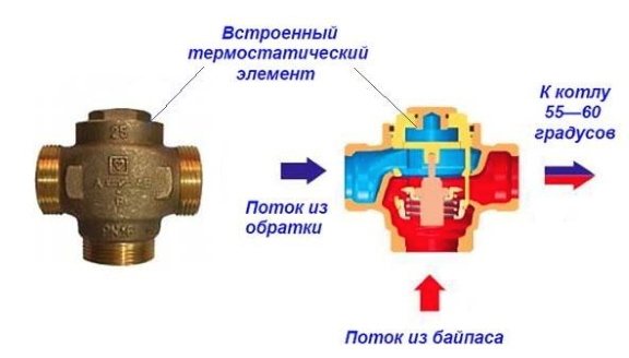
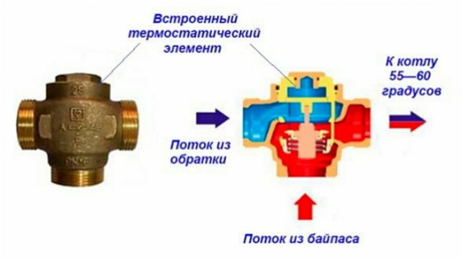
There are design options for the valve with a built-in temperature sensor, so it does not need a thermal head.
In the lists of equipment of companies you can find a lot of devices of this type, from all this you have to choose what you need, which is not always easy. In many respects, knowledgeable specialists of the trading organization will help to make the right choice. But you should not rely only on their opinion, it is better to figure out the issue yourself.
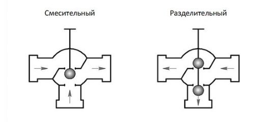
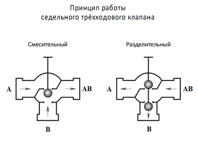
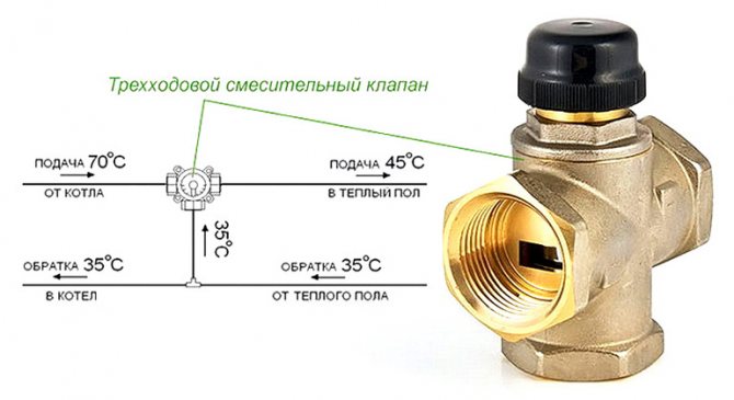
Mixing and separating three-way valves
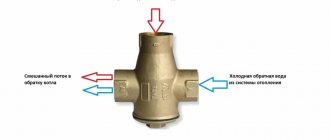
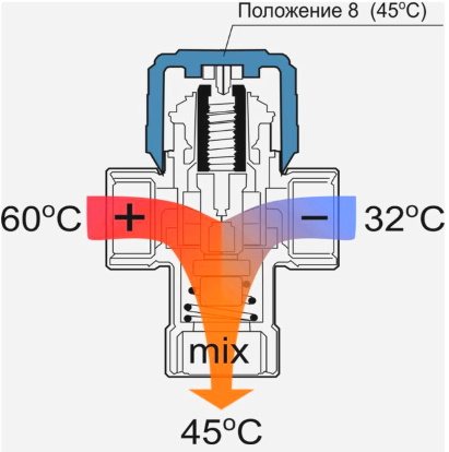
The three-way valve is a unit for mixing (dividing) liquid streams with three connections. Arrows on the valve body indicate the function it performs. For example, the device mixes 2 streams in different proportions depending on the position of the poppet valve.
In the first extreme position, only the first stream will enter the outlet, in the other extreme - only the second stream, in the middle position the streams will mix in equal proportions, for example.
- If liquids with different temperatures are supplied, then using the valve it is possible to regulate the temperature of the liquid at the outlet, obtained as a result of mixing the two streams.
The separation valve will divide the flows into 2 directions, mixing the coolant in one proportion or another into different branches. Its application is exactly the same as that of the mixing valve, only the installation along the branches is mirrored.
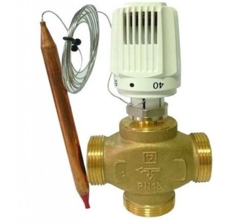
- On the basis of both valves, it is possible to create temperature control units in heating networks. In this case, the outlet temperature can be adjusted by a built-in temperature sensor or the valve can be controlled by a thermal head with a remote temperature sensor.
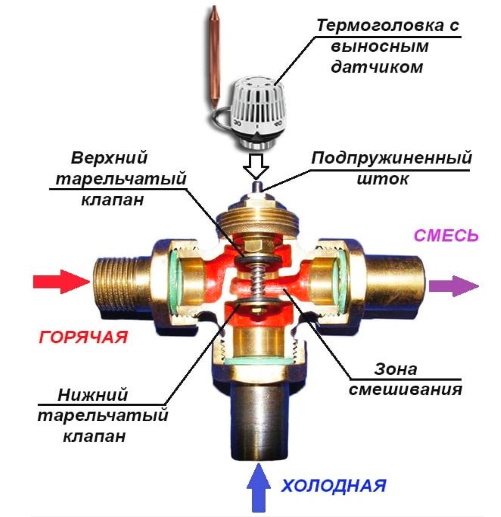
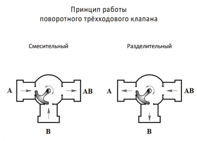
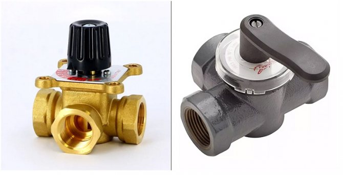
Three-way valve designs
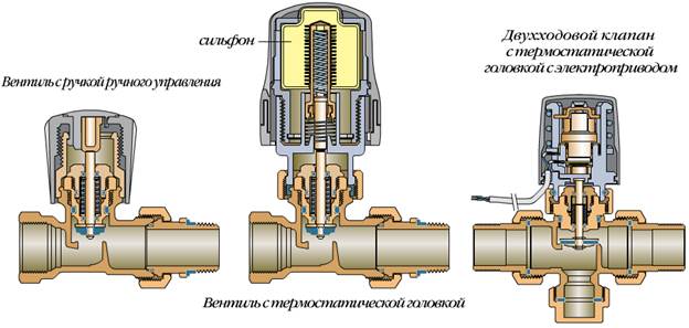
Globe valves are more commonly used, in which the seat moves on a spring-loaded stem and closes the inlets. This is a common design that is used with push action thermal heads.
Another option is a rotary ball switch. Switching between streams occurs when the regulator is turned, which is usually done by a servo drive on command from a temperature sensor. Such a system is more expensive and volatile.
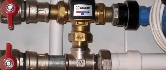
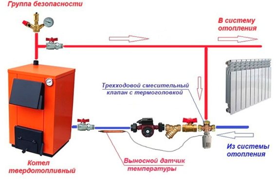
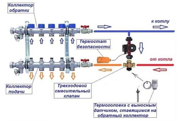
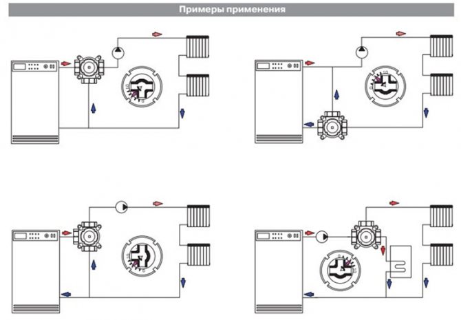
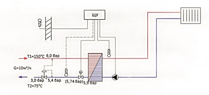
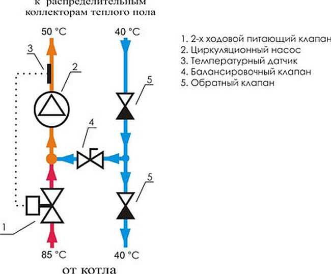
Three-way valve application diagram
A typical connection diagram for a three-way valve, to protect the heat exchanger of a solid fuel boiler from cold return. The coolant is mixed from the supply to the return in a small circle. The goal is to maintain always more than 55 degrees on the return, so that condensation of water vapor on the heat exchanger does not occur, and, accordingly, so that there is no significant pollution and acid corrosion.
The bellows sensor of the thermal head is installed on the return line and gives a command to the thermal head about the degree of pressure on the stem of the three-way mixing valve. The pre-opening is adjusted by turning the setting.
Where else are 3-way valves used?
Typical applications for controlling the temperature of the heating medium with three-way valves are as follows.
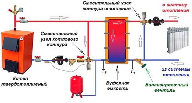
- Adjustment of the temperature of the heating agent supplied from the buffer tank. A charged heat accumulator may contain too hot liquid that is not required in the house. Therefore, the valve mixes the cold return flow into the supply stream according to the settings of the owners.
- Maintaining the temperature of the coolant in the underfloor heating circuits. For normal operation of underfloor heating, the supply temperature should not exceed 55 degrees. Boilers for the radiator network usually give out more. In most systems of underfloor heating, pumping and mixing units are installed that maintain a stable temperature with pressure drops and coolant flow rates.
- In complex heating schemes, where after the pressure equalizer (buffers, hydraulic arrows, rings), circuits with different temperature requirements are connected. It is safer to make the adjustment not by reducing the flow along the circuit, but by a mixing unit based on a three-way valve.
Instead of a three-way valve, in many schemes, a two-way valve can be used, which regulates the amount of flow, which will then be mixed at the tee into the main stream. But these units require a stable pressure, as well as a special calculation, so a two-way valve can be found in factory pumping and mixing units.
Sometimes only a fixed outlet temperature is required. A valve with a thermostatic device is cheaper ...
How to choose a three-way valve according to the capacity
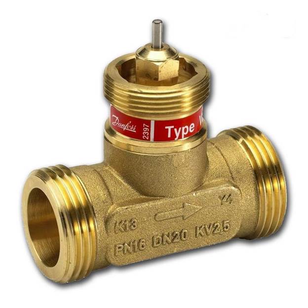
The main characteristic of a three-way valve is the nominal capacity, designated as Kvs, m³ / h. It is indicated assuming a pressure difference of 1 bar across the valve connections.
For example, in the catalog (in the characteristics) you can find Kvs = 2.5 in m³ / h, which means that at a pressure of 1 bar, 2.5 cubic meters of coolant will pass through a fully open valve per hour. But how to use this figure in real conditions?
- First, we need to know how much liquid we need to pass through such a valve? Second, what is the pressure drop across the valve in our circuit?
The required liquid flow rate Ktr, m3 / hour through the valve for any scheme is not difficult to calculate by the formula:
Three-way valve calculation
Ktr = 0.86 Q / ∆t, where Q is the branch power (heat load), for a boiler or heating circuit of the whole house, it is taken according to the heat generation power kW, ∆t is the difference between the supply and return temperatures, usually 20 degrees, and for a warm floor - 10 degrees.
Then, for piping a 20 kW boiler, liquids must pass through the valve at least Ktr = 0.86 20/20 = 0.86 cubic meters / hour, with a pressure drop of 1 bar.
But our pressure drop is much less - about 0.2 bar. At this pressure, the throughput of the valve should be much higher. Which exactly?
- The pressure drop for any circuit between supply and return will not exceed 0.2 bar, typically between 0.1 and 0.2 bar.
There is a certain empirical formula in this regard - the throughput of the valve in our circuit should be no less than
K = Ktr / √r, cubic meters / hour, K = 0.86 / √0.2 = 1.9 m³ / h.
We select a valve with a higher characteristic: Kvs is more than K, but not much, so as not to overpay for the volume of the structure, Kvs = 2.5 m³ / h is suitable.
We select a three-way mixing valve with such a capacity from a well-known manufacturer and we believe that it provides us with normal mixing in a circuit with a power of 20 kW.
In general, the selection of thermal heads, their placement, setting up work with the selected three-way or two-way valve is not an easy task. For beginners, it is advisable to consult at least an experienced seller with a demonstration of installation and instructions for use, creating a mixing unit, and determining whether it is suitable for a specific scheme. Moreover, if you plan to use an electric drive. Or it remains to entrust this work to a specialist.
Areas of use
As noted above, this type of control valve is used in heating, ventilation and air conditioning systems. Let us consider separately the features of its use in a circuit with a "warm floor".
If a boiler is installed in the house, then its task is to heat the water and, as a rule, its temperature is quite high, suitable for radiators (from +75 to +95 degrees Celsius). For the "warm floor" system, such heating is not needed, since sanitary standards regulate a maximum of +35 degrees Celsius. This figure is enough to walk comfortably on the floor. If the temperature is higher, this will not only cause inconvenience to residents, but also negatively affect the finish floor covering. For example, linoleum or laminate flooring is easily deformed.
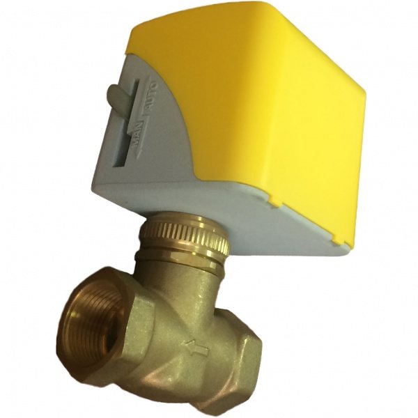
"Warm floor" is mounted under the screed, in addition, different flooring materials are used. For this, the coolant is heated to +50 degrees Celsius. When underfloor heating is directly connected to a boiler or centralized heating system, the resulting temperature is too high. To lower it at the entrance to the circuit, a mixing valve for a warm floor is mounted, with a two-way or three-way valve already provided. As the name suggests, the purpose of such fittings is to mix hot and cold water circulating along the circuit. That is, the process of fluid passage changes - for the radiator, the water remains hot, and the already mixed, having a lower temperature, enters the warm floor.
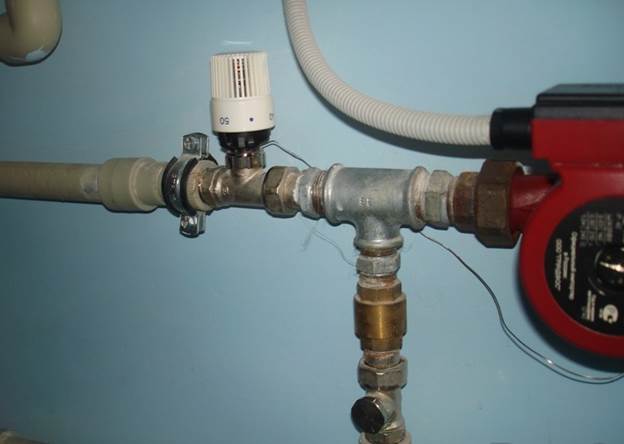
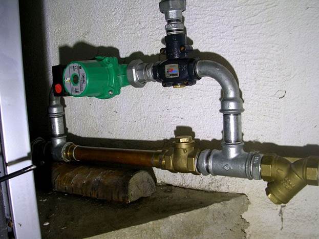
Installed valve
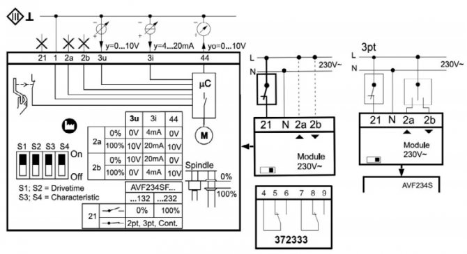
Areas of application of communication modules
The device, which can be purchased profitably in our store, can be used in the heating control structure to regulate and optimize the operation of heating systems in accordance with the data of external weather sensors and internal temperature sensors.
The device is a necessary element when connecting remote control units or room displays to control a multi-circuit heating system.
It serves to receive information from internal and external water and air temperature sensors and to directly or indirectly control the temperature in the heating system, control the operation of boilers or pumps.
The communication module can also be used to control valves in various industries.
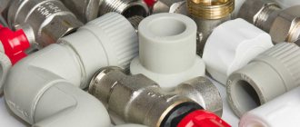
What materials is it made of
Cast iron, brass and steel products are now common. For example, fittings made of cast iron and steel are installed in pipeline systems with a large flow of water or steam. Brass valves are often found in ventilation systems. Their main advantage is their compact size, so the element is mounted even in small rooms with limited water consumption.
A steel or cast iron control valve is recommended. Steel products are common, which are as strong as their cast iron counterparts, but much cheaper. When choosing a material, the characteristics of the pressure in the system and the dimensions of the valve itself are taken into account.
Steel valve
Service life of three-way valves
The most important factors affecting the life of a three-way:
- The material from which it is made.
- Compliance with the operating conditions prescribed by the manufacturer - the temperature regime and the quality of the coolant.
- Intensity of exploitation.
- Installation quality.
On average, manufacturers give a guarantee for their products in the range of 5 to 7 years, which means that a three-way valve can easily work 2 times longer. But the warranty for plastic models does not exceed 1 year.
Valves with a manual control system have always been recognized as the most reliable. Electronic and thermostatic sensors fail much faster than the valve itself and require repair or complete replacement.
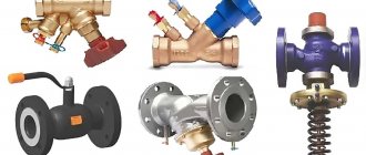
Types of control valves
The fittings differ in several ways.
Depending on the design features, 2 types are distinguished:
- pass-through - in them the nozzles have the opposite location;
- angular - located at an angle of 90 degrees.
Pay attention to how the valve is controlled.
According to this parameter, 3 types are distinguished:
- pneumatic;
- hydraulic;
- equipped with an electric drive.
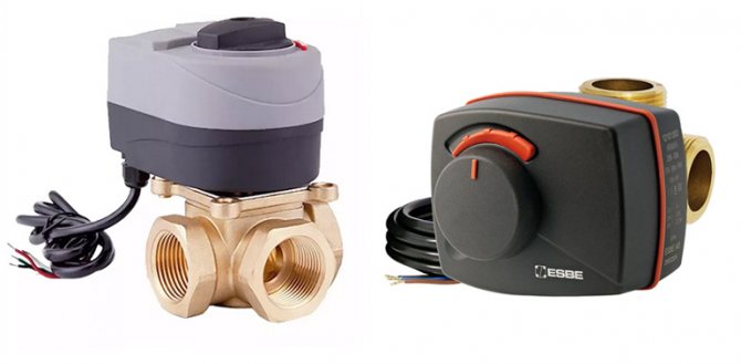
The electric driving device is a low-power electric motor or retraction solenoids. Of course, there are products with manual control, but they are more difficult to operate, since they do not allow setting the exact parameters. The devices operate on an electrical network with an alternating current of 220 V or constant 24 V.
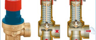
Certain pass-through nodes operate autonomously, without power supply. Such valves are controlled and regulated by means of a diaphragm and a spring opposing it. As a feedback, a stroke is used along which the coolant moves - it also directs the membrane in the right direction.
What the two-way valve gives:
- consumption is regulated, resources (water) are distributed and saved;
- more economical heat consumption;
- equipment and networks are protected from pressure drops;
- if used correctly, the valve will extend the life of the connected equipment and the network itself.
Devices are fastened with flanges, threaded or welded.One of the subspecies of the threaded connection is the pin mount, in which the valve is screwed into another device. When the installation is welded, special branch pipes are used.
Separately, we highlight the remote-controlled valve, which is the easiest to operate. Such devices are complemented by electric drives or consoles. It is the control rooms that receive all the current characteristics and parameters of the system. Remotely decreases, increases the pressure or overlaps certain branches of the heating network.
A kind of two-way valve
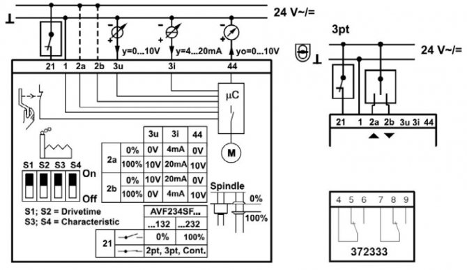
Rotary control valves for steam, gas with electric actuator
In assortment - control valve with Danfoss electric actuator, represented by two- and three-way models (the gear actuator is purchased separately), and one- and two-seat shut-off and control valves with an electric drive Broen. The valves are used at central and individual heating points, supply ventilation systems for greenhouses, in water supply systems and other areas of the economy as a shut-off device or to automate the regulation of technological processes. The design of the steam control valve is carried out in accordance with the regulations. The valves are used with electric actuators, thermostats, pneumatic actuators, differential pressure regulators, which you can purchase separately. Here you will find accessories for the installation and ensuring the smooth operation of the valves.
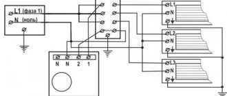
Connection diagram
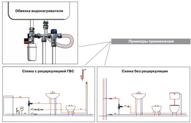
For water-heated floors, the valve is most often installed in parallel. For its implementation, 2 or 3 heating circuits with a circulating heat carrier must be used. Water supply and pressure are regulated by one or more valves installed in parallel. When mixing the coolant in parallel, the underfloor heating lines must be disconnected in advance.
As a rule, the control taps are adjusted independently, manually, where the required volume of the passed water is set.
Important! If a parallel circuit is used, it is recommended to replace the bypass with a bypass valve. This is done in order to reduce the operating load and save energy supplied to the pump.
The circuit has a minus - the coolant entering the circuit will be the same temperature as the water leaving the return circuit to the boiler. Because of this, hot water is distributed unevenly along the circuits.
Underfloor heating installation scheme
Installation features
The procedure itself boils down to the fact that the valve is connected to the necessary pipelines. In order for the fittings to work for a long time and without problems, the connection should be correctly implemented, taking into account all the tips and recommendations. If you lack experience, it is recommended to contact a specialist. Otherwise, the heating system will not be as efficient and economical as it should be.
Before proceeding with the installation work, pay attention to the two-way valve - there is an external or internal thread on its body, onto which the union nut (or fitting) of the pipeline is screwed. For a reliable connection, experts advise to wrap the thread with a sealant, which is suitable for FUM tape.
The set of fittings includes special gaskets to ensure the proper level of tightness. If they are not available, then they will have to be purchased separately, of the appropriate thickness and diameter. The main task is to ensure a tight connection, without distortions on the thread, which will prevent possible leaks. No special tools and devices are required.
Note! Two-way valves do not function in the simplest conditions, namely, under the influence of high temperatures. Because of this, threaded connections can lose their tightness, so the connection procedure must be carried out responsibly.
Expert advice:
- During installation, make sure that there are no forces in the piping.
- Before installing the element on the water supply, the latter should be thoroughly cleaned, removing all impurities. They have a negative effect on the condition of the sealing materials, as a result of which the tightness of the valve is compromised.
- Over time, the device may need to be repaired or dismantled, so leave enough space around it.
- Careful installation is important. If a flange connection is used, it is recommended to tighten the corresponding screws alternately to avoid internal stress. With the threaded method of installation, adjusting ties are used, which will allow to dismantle the valve in the future.
- If it is necessary to purge or flush the entire pipeline system, the valve is removed, and an adapter is put in its place.
Installation is a complex process and largely depends on the chosen scheme. To avoid mistakes, we recommend ordering a valve installation service from specialists.
Valve in the heating system
Installation process
Installation of a two-way valve for heating consists in its correct connection to the pipeline. The connection should be made using an internal or external thread. To do this, you need to screw a union nut or fitting onto it. Beforehand, the pipeline thread must be protected with a sealing material (FUM tape or natural sealant). Installation should be carried out taking into account the fact that high temperature affects the tightness of the threaded connection of the parts, weakening it.
Two-way valves are completed with special gasketsto be used during installation. They will make the connections as tight as possible, prevent possible leakage of the coolant from the line. If necessary, they can be replaced with the same gaskets, suitable in diameter and thickness.