Heating is one of the privileges people need to live comfortably. To prevent each apartment from connecting separate heating, a whole system is installed in the house. Such systems differ depending on the type of house, its size and the number of apartments.
In the paragraphs of this article, we will try to answer in detail the questions regarding the heating network at home.
How is the process of heat supply of a high-rise building
Each apartment building has a central heating system, which consists of the following elements:
- a source;
- heating network;
- consumer.
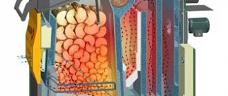
Boiler houses and thermal power plants act as sources of heat energy.
From boiler rooms to houses, hot water is directed immediately and requires a decrease in temperature, otherwise the heating equipment of the house will be damaged. In a CHP plant, it is converted into steam to generate electricity, then this steam is used to heat the coolant entering the building's heating network.
Rules and regulations applied in MKD heat supply systems
"The temperature of hot water at the points of water intake, regardless of the heat supply system used, must be at least 60 ° C and not higher than 75 ° C."
The hot water temperature must be more than 60 degrees Celsius to disinfect it from viruses and bacteria, which can survive at lower temperatures, but die at values above this figure.
On the other hand, the use of water heated above 75 degrees is unacceptable, as it can lead to burns.
We offer you to familiarize yourself with Heat meters
a. in residential premises - not lower than 18 ° С (in corner rooms 20 ° С);
b. in areas with a temperature of the coldest five-day week -31 ° C and below 20 ° C (in corner rooms from 22 ° C);
c. in other premises, in accordance with the requirements of the legislation of the Russian Federation on technical regulation.
2. The heating system must provide a permissible excess of the standard temperature of no more than 4 ° C;
3. Permissible decrease in the standard temperature at night (from 0.00 to 5.00 hours) - no more than 3 ° C;
4. Reducing the air temperature in the living quarters during the daytime (from 5.00 to 0.00 hours) is not allowed.
What is "heating network" and "heating unit"
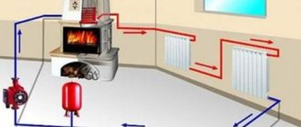
The heating network of a house is a collection of pipelines that provide heat to each living space. This is a complex system that consists of two heat pipes: hot and cooled.
Heating unit - heating equipment system; the place where the hot water pipe merges with the building heating system. Distribution and metering of heat takes place here.
The list of performed tasks includes:
- control over the state of the heat source;
- monitoring the condition of water and heat pipelines;
- registration of data from metering devices.
Types of heating units
In multi-storey buildings, heating points of two types are used.
Single-circuit provides a direct connection to hot water pipes, that is, heat pipes are connected using an elevator. In high-rise buildings, the heating network is quite extensive, but most of the equipment is located in the basement.
Important! The scheme of a two-circuit heating unit is a system of two heat pipes in contact with each other through a heat exchanger.
Further, we will consider in more detail the principle of operation of a single-circuit heating unit.Due to its structure, namely the presence of an elevator, and its low cost, it is used most often. For companies that are engaged in the installation of heating equipment and heating units, it is more profitable to use outdated elevator units that do not require careful attention.
Device
A single-circuit heating unit is designed in the simplest way. As already mentioned, it consists of a pipe extending from a heat source and a "cold" pipe, which are connected by means of an elevator. Also on the pipes there are filters and measuring devices that control the flow, the temperature of the coolant and the pressure in the pipes.
The filtering equipment is installed, since the entire heating system reacts rather negatively to dirt and sediment in the coolant. Over time, it must be cleaned or changed.
Important! If the pressure is unstable, a device that lowers it is installed in the heating unit.
Installation of counters has some nuances:
- placed on a pipe with "return" heat;
- it must be located as close as possible to the heat source;
- setting of parameters (required amount of heat per hour, day).
Functioning principle
In this paragraph, we will tell you what processes take place inside the elevator heating unit.
According to the scheme, hot water supplied by utilities enters the house through a "hot" pipe. Having “bypassed” the entire building, it returns to the unit in a cooled state and is removed from the system. But in the elevator, hot and "cold" water is mixed, not allowing the temperature to go beyond the permissible limits. There are situations (suitable for areas with low temperatures) a heating mechanism is built into the elevator: if the temperature of the water during mixing is below the permissible level, the mechanism turns on.
The intra-building heating system can be disconnected from the city heating system using valves. Such actions are carried out during repair work and for general prevention. For such cases, there are special valves on the pipes designed to remove water from the system.
Important! All parts of the unit are connected to the heating system using flange connections.
The use of a single-circuit unit has both advantages and disadvantages.
The advantages of such a heating unit are:
- ease of use;
- the rarity of breakdowns;
- the relative cheapness of the components and their installation;
- fully mechanized and does not depend on extraneous energy sources.
The main negative sides:
- for each heat pipe, personal calculations of parameters are required for the selection of an elevator;
- the pressure in each pipe must be different;
- manual adjustment only;
- Who carries out the installation and maintenance of the heating unit.
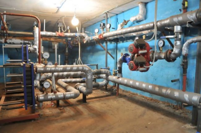
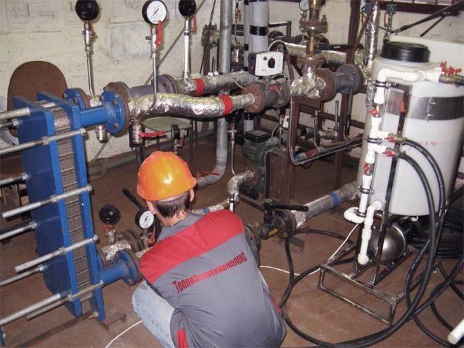
Houses with a large number of apartments have a system for supplying heat and hot water from the city, which is located in the basement. Such a heating system needs preventive maintenance. The most "weak link" are filters, or mud collectors, which must be monitored and cleaned (they accumulate all the dirt from the coolant).
This work is done, or at least should be done, by the locksmiths from the housing and communal services bodies that serve the building. Since the heating center is complex and dangerous in operation, in no case is the intervention of unauthorized people allowed, and only specially trained personnel are allowed to carry out diagnostics and repairs.
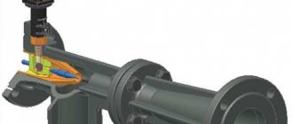
Unit characteristics and features of work
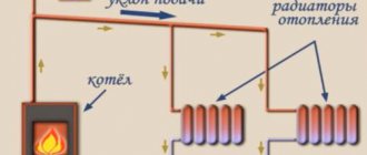
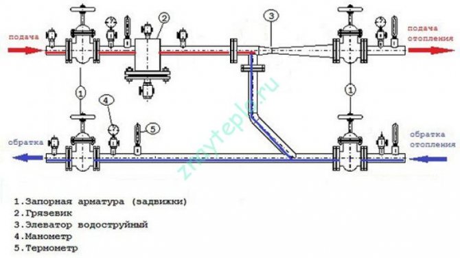
According to the diagrams, it can be understood that an elevator in the system is needed to cool the overheated coolant. Some designs have an elevator that can heat water. This heating system is especially relevant in cold regions. The elevator in this system starts only when the cooled liquid mixes with the hot water coming from the supply pipe.
Scheme. The number "1" designates the supply line of the heating network. 2 is the return line of the network.The number "3" indicates an elevator, 4 - a flow regulator, 5 - a local heating system.
According to this scheme, it can be understood that the unit significantly increases the efficiency of the entire heating system in the house. It works simultaneously as a circulation pump and a mixer. As for the cost, the node will cost quite cheaply, especially the option that works without electricity.
But any system also has drawbacks, the collector unit is no exception:
- Separate calculations are required for each element of the elevator.
- Compression drops should not exceed 0.8-2 bar.
- The inability to control the high temperature.
The installation of a heating system regulator will depend on its overall design. If the CO is mounted individually for a specific room, the improvement process takes place due to the following factors:
- the system is powered by an individual boiler;
- a special three-way valve is installed;
- the pumping of the coolant is compulsory.
In general, for all COs, the work on adjusting the power will consist in installing a special valve on the battery itself.
With its help, it is possible not only to regulate the level of heat in the required rooms, but also to exclude the heating process altogether in those areas that are poorly used or do not function.
There are the following nuances in the process of adjusting the heat level:
- Central heating systems that are installed in multi-storey buildings are often based on heating fluids, where the supply is strictly vertical from top to bottom. In such houses, it is hot on the upper floors, and cold on the lower ones, so it will not be possible to adjust the heating level.
- If a single-pipe network is used in houses, then heat from the central riser is supplied to each battery and returned back, which ensures uniform heat on all floors of the building. In such cases, it is easier to install heat regulation valves - the installation takes place on the supply pipe and the heat continues to spread evenly as well.
- For a two-pipe system of risers, two are already installed - heat is supplied to the radiator and in the opposite direction, respectively, the control valve can be installed in two places - on each of the batteries.
Modern technologies are far from standing still and allow for each heating radiator to install a high-quality and reliable tap that will control the level of heat and heating. It is connected to the battery with special pipes, which will not take much time.
According to the types of regulation, I distinguish two types of valves:
- Conventional direct-acting thermostats. Installed next to the radiator, it is a small cylinder, inside which a liquid or gas siphon is hermetically located, which quickly and competently reacts to any temperature changes. If the temperature of the battery rises, the liquid or gas in such a valve expands, pressure will occur on the stem of the heat regulator valve, which will move and cut off the flow. Accordingly, if the temperature drops, the process will be reversed.
Photo 1. Diagram of the internal device of the thermostat for the battery. The main parts of the mechanism are indicated.
- Thermoregulators based on electronic sensors.The principle of operation is similar to conventional regulators, only the settings differ - everything can be done not in manual mode, but in electronic mode - to lay down the functions in advance, with a possible time delay and temperature control.
We offer you to familiarize yourself with Electric heat guns - the principle of operation, how to choose, the best models, prices and reviews, where to buy
The standard process for regulating the temperature of heating radiators consists of four stages - bleeding air, adjusting the pressure, opening the valves and pumping the coolant.
- Bleeding air.Each radiator has a special valve, opening which you can release excess air and steam that interferes with heating the battery. Within half an hour after this procedure, the required heating temperature must be reached.
- Pressure regulation. So that the pressure in the CO is evenly distributed, you can turn the shut-off valves of different batteries attached to one heating boiler by a different number of revolutions. Such an adjustment of the radiators will allow the room to be heated as quickly as possible.
- Opening the valves. Installing special three-way valves on radiators will allow you to remove heat in unused rooms or limit heating, for example, during your absence from the apartment during the day. It is enough just to close the valve completely or partially.
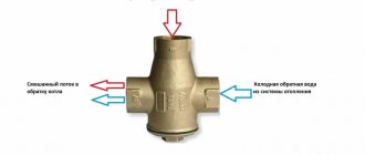
Photo 2. A three-way valve with a thermostat that allows you to easily adjust the temperature of the heating radiator.
- Coolant pumping If CO is forced, the coolant is pumped using control valves, with the help of which a certain amount of water is drained to give the heating radiator an opportunity for heating.
In the paragraphs of this article, we will try to answer in detail the questions regarding the heating network at home.
general information
The heating point is located at the entrance of the heating main into the premises. Its main task is to change the operating parameters of the heat-transfer fluid, and to be more precise, to reduce the temperature and pressure of the water before it enters the radiator or convector. Such a process is necessary not only to increase the safety of residents and prevent possible scalding on contact with the battery, but also to increase the operating life of all equipment. The function is indispensable in cases where the building has polypropylene or metal-plastic pipes.
The relevant documentation indicates the regulated modes of operation of such units. They indicate the upper and lower temperature thresholds to which the coolant can be heated. Also, according to modern standards, a heat sensor must be present at each unit, which determines the current indicators of the liquid with which the heating unit operates.
The scheme, principle of operation and design of thermal equipment may depend on several features, including a project that was created taking into account the individual requirements of customers. Among the existing types of heating units, models based on an elevator are in special demand. Such a scheme is characterized by particular simplicity and availability, but with its help it is impossible to change the temperature of the liquid in the pipes, which gives the consumer a lot of inconvenience. The main problem is the excessive consumption of heat resources during temporary thaws during heating.
In the system of heating units based on an elevator, a reduced pressure reducer may be present, which is located directly in front of the elevator. The elevator itself mixes the cooled liquid from the return pipe to the heated coolant that has reached the supply circuit.
How does the Elevator unit heating
The device of a thermal unit implies a mass of components that are interdependent and function for one common purpose.
Among the main elements of the system:
- Shut-off valves.
- Heat meter.
- Sump.
- Heat carrier flow sensor.
- Return pipe heat sensor.
- Optional equipment.
Depending on the individual characteristics of the object, the system can be equipped with additional sensors and other units. As for the installation, it must be carried out taking into account certain rules and requirements:
- The installation of the scheme should take place directly at the boundaries of the section of the balance sheet.
- It is strictly forbidden to use a coolant from a common communal system for individual needs.
- To control the hourly and daily average indicators, it is necessary to take into account the working properties of the accounting equipment.
- Any sensors and accounting devices are fixed on the "return" pipeline.
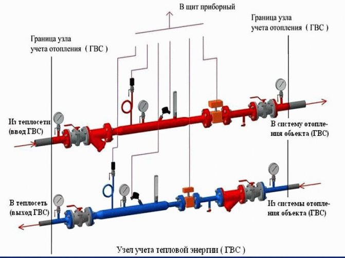
Heat metering unit. On practice. The device of an apartment building.
There is another type of heating unit for a private house - based on a heat exchanger. In this case, a special heat exchanger is connected to the device, which separates the liquid from the heating main from the liquid in the room. A similar function is necessary for additional preparation of the coolant using various additives and filtering devices.
Thermostatic valves must be used to mix water at different temperatures. Such systems normally interact with aluminum radiators, but in order for the latter to last as long as possible, it is necessary to carefully choose the coolant, refusing to use low-quality raw materials. Of course, keeping track of the quality of the liquid is problematic, so it is better to abandon this material, preferring bimetallic or cast-iron radiators.
The DHW connection diagram implies the use of a heat exchanger. This method provides many benefits, including:
- Possibility of water temperature regulation.
- Possibility of changing the pressure of the hot coolant.
Heat exchangers and block individual heating points
Elevator units
In multi-apartment and multi-storey buildings, administrative buildings and other facilities with a large area, highly efficient CHP plants or powerful boiler houses are used. In private cottages and small houses, simple autonomous systems are used that work according to an understandable principle.
However, even with such installations, certain problems arise, because of which it becomes difficult to carry out adjustments or changes in operating parameters. And in large boiler houses or thermal power plants, the schemes of such equipment are much more complex and larger. A mass of branches diverges from the central pipe to each consumer.
- Insulation of pipes and the use of new materials for their manufacture.
- Increase in water temperature at the outlet of the boiler room.
Heating in an apartment building
Possible problems
The thermal system of a house is a complex mechanism. Any breakdowns and malfunctions are inevitable. But most often problems arise in the heating unit, namely, the breakdown of the elevator. Mechanical reasons: flaws in the locking equipment, clogged filters. This creates a temperature difference in the pipes before and after passing the elevator. If the difference is not big, then the problem is not serious: you just need to clean the elevator. Otherwise, repairs are needed.
Other problems of the heating unit include an increase in the permissible temperature of the measuring equipment, the occurrence of leaks in the pipes. When the filters become clogged, the pressure in the pipes increases.
Important! In the event of any malfunction, it is necessary to diagnose the entire heating system.
As mentioned in the article, elevator units are an obsolete technology. Gradually, in apartment buildings, they are replaced with automatic heating units, which do not require constant monitoring by a person and regulate all indicators themselves.
The disadvantage of such heating systems is the high cost and, like any automated device, it runs on electricity.
However, devices are built into the scheme of single-circuit units that make it possible to regulate the temperature and pressure in the incoming coolant. Thus, it allows people to save money when paying for communal services.
How is the heating unit arranged?
In general, the technical device of each substation is designed separately, depending on the specific requirements of the customer. There are several basic schemes for the execution of heat points.Let's take a look at them in turn.
Heating unit based on an elevator.
The scheme of a heating point based on an elevator unit is the simplest and cheapest. Its main drawback is the inability to regulate the temperature of the coolant in the pipes. This causes inconvenience for the end user and a large waste of heat energy in the event of thaws during the heating season. Let's take a look at the figure below and see how this circuit works:
In addition to what is indicated above, the heating unit may include a pressure reducing reducer. It is installed in the feed in front of the elevator. The elevator is the main part of this circuit, in which the cooled coolant from the "return" is mixed with the hot coolant from the "feed". The principle of operation of the elevator is based on creating a vacuum at its outlet. As a result of this vacuum, the pressure of the coolant in the elevator turns out to be less than the pressure of the coolant in the "return" and mixing occurs.
Heat unit based on a heat exchanger.
The heating point connected through a special heat exchanger allows separating the coolant from the heating main from the coolant inside the house. Separation of coolants allows its preparation with the help of special additives and filtration. With this scheme, there are ample opportunities in regulating the pressure and temperature of the coolant inside the house. This helps to reduce heating costs. In order to have a visual idea of such a design, look at the figure below.
The mixing of the coolant in such systems is done using thermostatic valves. In such heating systems, in principle, it is possible to use aluminum heating radiators, but they will last a long time only with good quality of the coolant. If the PH of the coolant goes beyond the limits approved by the manufacturer, then the service life of aluminum radiators can be greatly reduced. You cannot control the quality of the coolant, so it is better to play it safe and install bimetallic or cast iron radiators.
DHW can be connected in a similar way via a heat exchanger. This offers the same benefits in terms of hot water temperature and pressure regulation. It is worth saying that unscrupulous management companies can deceive consumers by lowering the temperature of hot water by a couple of degrees. For the consumer, this is almost invisible, but on a scale at home it allows you to save tens of thousands of rubles a month.
Modern ITP
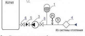
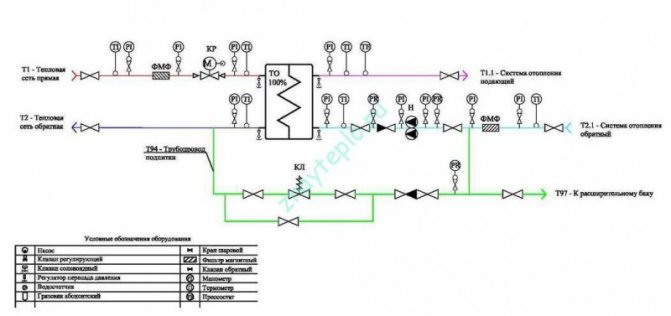
Energy saving is achieved, in particular, by regulating the temperature of the heating medium, taking into account the correction for the change in the outside air temperature. For these purposes, each ITP uses a set of equipment (Fig. 4) to ensure the necessary circulation in the heating system (circulation pumps) and control the temperature of the coolant (control valves with electric drives, controllers with temperature sensors).
Fig. 4. Schematic diagram of an individual substation using a controller, a regulating valve and a circulation pump
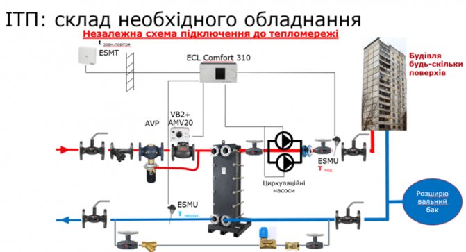
Most individual heating points also include a heat exchanger for connection to an internal hot water supply (DHW) system with a circulation pump. The set of equipment depends on the specific tasks and initial data. That is why, due to the various possible design options, as well as its compactness and portability, modern ITPs are called modular (Fig. 5).
Fig. 5. Modern modular individual heating station assembled
Consider the use of ITP in dependent and independent schemes for connecting the heating system to a centralized heating network.
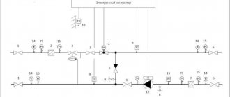
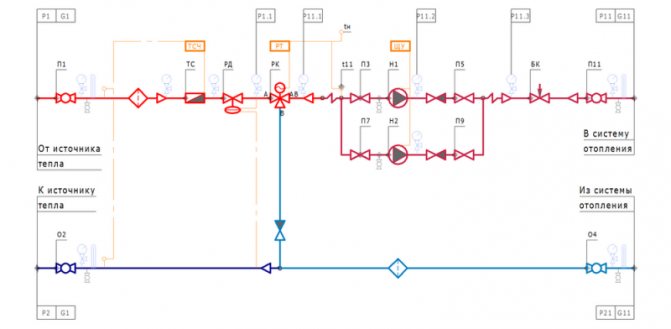
In an ITP with a dependent connection of the heating system to external networks, the circulation of the coolant in the heating circuit is supported by a circulation pump.The pump is controlled automatically from the controller or from the appropriate control unit. Automatic maintenance of the required temperature schedule in the heating circuit is also carried out by an electronic controller. The controller acts on a control valve located on the supply pipe on the side of the external heating network ("hot water"). A mixing jumper with a check valve is installed between the supply and return pipelines, due to which the mixture into the supply pipeline from the return line of the coolant with lower temperature parameters is carried out (Fig. 6).
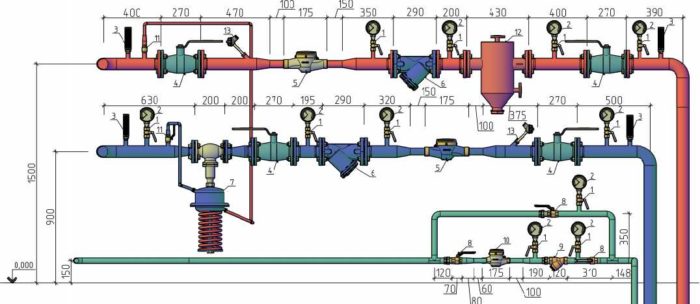
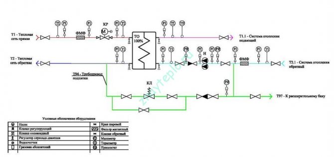
Fig. 6. Schematic diagram of a modular substation connected according to a dependent scheme: 1 - controller; 2 - two-way control valve with electric drive; 3 - coolant temperature sensors; 4 - outside air temperature sensor; 5 - pressure switch to protect pumps from dry running; 6 - filters; 7 - gate valves; 8 - thermometers; 9 - manometers; 10 - circulation pumps of the heating system; 11 - check valve; 12 - circulating pump control unit
In this scheme, the operation of the heating system depends on the pressures in the central heating network. Therefore, in many cases, it will be necessary to install differential pressure regulators, and, if necessary, pressure regulators "behind" or "before" on the supply or return pipelines.
In an independent system, a heat exchanger is used to connect to an external heat source (fig. 7). The circulation of the coolant in the heating system is carried out by a circulation pump. The pump is controlled automatically by the controller or the appropriate control unit. Automatic maintenance of the required temperature schedule in the heated circuit is also carried out by an electronic controller. The controller acts on an adjustable valve located on the supply pipe on the side of the external heating network ("hot water").
Fig. 7. Schematic diagram of a modular substation connected according to an independent scheme: 1 - controller; 2 - two-way control valve with electric drive; 3 - coolant temperature sensors; 4 - outside air temperature sensor; 5 - pressure switch to protect pumps from dry running; 6 - filters; 7 - valves; 8 - thermometers; 9 - manometers; 10 - circulation pumps of the heating system; 11 - check valve; 12 - circulation pump control unit; 13 - heat exchanger of the heating system
The advantage of this scheme is that the heating circuit is independent of the hydraulic modes of the centralized network. Also, the heating system does not suffer from inconsistencies in the quality of the incoming heat carrier coming from the external network (the presence of corrosion products, dirt, sand, etc.), as well as pressure drops in it. At the same time, the cost of capital investments when using an independent scheme is higher - due to the need to install and subsequently maintain a heat exchanger.
As a rule, in modern systems, gasketed plate heat exchangers are used (Fig. 8), which are quite easy to maintain and maintainable: in case of loss of tightness or failure of one section, the heat exchanger can be disassembled and the section replaced. Also, if necessary, you can increase the power by increasing the number of heat exchanger plates. In addition, in independent systems, brazed non-separable heat exchangers are used.
Fig. 8. Heat exchangers for independent ITP connection systems
According to DBN V.2.5-39: 2008 “Engineering equipment of buildings and structures. External networks and facilities. Heating networks ", in the general case, the connection of heating systems is prescribed according to a dependent scheme. An independent scheme is prescribed for residential buildings with 12 or more floors and other consumers, if this is due to the hydraulic mode of the system or the customer's specifications.
equipment requirements
The most important characteristic of a modern individual heating unit is the availability of heat energy metering devices, which is mandatory provided by DBN V.2.5-39: 2008 “Engineering equipment of buildings and structures. External networks and facilities. Heating network".
According to section 16 of these standards, equipment, fittings, monitoring, control and automation devices must be placed in the ITP, with the help of which they carry out:
- regulation of the temperature of the coolant according to weather conditions;
- changing and monitoring the parameters of the coolant;
- accounting for heat loads, heat carrier and condensate costs;
- regulation of heat carrier costs;
- protection of the local system from an emergency increase in the parameters of the coolant;
- additional treatment of the coolant;
- filling and replenishment of heating systems;
- combined heat supply using thermal energy from alternative sources.
The connection of consumers to the external network should be carried out according to schemes with minimal water consumption, as well as saving thermal energy by installing automatic heat flow regulators and limiting the costs of network water. It is not allowed to connect the heating system to the heating network through an elevator together with an automatic heat flow regulator.
It is prescribed to use highly efficient heat exchangers with high thermal and operational characteristics and small dimensions. Air vents should be installed at the highest points of TP pipelines, and it is recommended to use automatic devices with non-return valves. At the lowest points, fittings with shut-off valves for draining water and condensate should be installed.
A mud collector should be installed at the entrance to an individual heating point on the supply pipeline, and strainers should be installed in front of pumps, heat exchangers, control valves and water meters. In addition, a mud filter must be installed on the return line in front of the regulating devices and metering devices. Pressure gauges should be provided on either side of the filters.
To protect the DHW channels from scale, the norms prescribe the use of magnetic and ultrasonic water treatment devices. Forced ventilation, which must be equipped with an IHP, is designed for short-term action and must provide a 10-fold exchange with an unorganized inflow of fresh air through the entrance doors.
In order to avoid exceeding the noise level, the ITP is not allowed to be located next to, under or above the premises of residential apartments, bedrooms and kindergarten games rooms, etc. In addition, it is regulated that the installed pumps must be with an acceptable low noise level.
An individual heating point should be equipped with automation equipment, devices for thermal control, metering and regulation, which are installed on site or on a control panel.
ITP automation should provide:
- regulation of heat energy consumption in the heating system and limitation of the maximum consumption of network water at the consumer;
- set temperature in the DHW system;
- maintaining static pressure in the systems of heat consumers when they are independently connected;
- set pressure in the return pipeline or the required pressure drop of water in the supply and return pipelines of heating networks;
- protection of heat consumption systems from high pressure and temperature;
- turning on the backup pump when turning off the main worker, etc.
In addition, modern projects provide for the arrangement of remote access to the control of individual heating points. This allows you to organize a centralized dispatching system and monitor the operation of heating and hot water systems.Equipment suppliers for ITP are leading manufacturers of relevant equipment, for example: automation systems - Honeywell (USA), Siemens (Germany), Danfoss (Denmark); pumps - Grundfos (Denmark), Wilo (Germany); heat exchangers - Alfa Laval (Sweden), Gea (Germany), etc.
It is also worth noting that modern ITPs include rather complex equipment that requires periodic maintenance and service, which, for example, includes flushing the strainers (at least 4 times a year), cleaning heat exchangers (at least once every 5 years), etc. .d. In the absence of proper maintenance, the equipment of the substation may become unusable or malfunction. Unfortunately, there are already examples of this in Ukraine.
At the same time, there are pitfalls in the design of all ITP equipment. The fact is that in domestic conditions, the temperature in the supply pipeline of a centralized network often does not correspond to the standardized temperature, which is indicated by the heat supply organization in the technical conditions issued for design.
{{ORDER_M_RU}
At the same time, the difference in official and real data can be quite significant (for example, in reality, a coolant is supplied with a temperature of no more than 100 ° C instead of the indicated 150 ° C, or there is an unevenness of the coolant temperature from external networks over the time of day), which, accordingly, affects on the choice of equipment, its subsequent work efficiency and, as a result, on its cost. For this reason, it is recommended, when reconstructing an ITP at the design stage, to measure the real parameters of heat supply at the facility and take them into account in the future when calculating and choosing equipment. At the same time, due to the possible discrepancy between the parameters, the equipment should be designed with a margin of 5–20%.
Implementation in practice of an individual heating point
The first modern energy efficient modular ITPs in Ukraine were installed in Kiev in the period 2001-2005. within the framework of the World Bank project "Energy Saving in Administrative and Public Buildings". A total of 1173 ITPs were installed. To date, due to previously unresolved issues of periodic qualified maintenance, about 200 of them have become unusable or require repair.
Types of heat points
TPs differ in the number and type of heat consumption systems connected to them, the individual characteristics of which determine the thermal scheme and characteristics of the TP equipment, as well as by the type of installation and features of the equipment placement in the TP room. There are the following types of TP:
- Individual heating point
(ETC). Used to service one consumer (building or part of it). As a rule, it is located in the basement or technical room of the building, however, due to the characteristics of the serviced building, it can be placed in a free-standing structure. - Central heating point
(TSC). It is used to service a group of consumers (buildings, industrial facilities). Most often it is located in a freestanding building, but it can be located in the basement or technical room of one of the buildings. - Block heat point
(BTP). Manufactured at the factory and supplied for installation in the form of ready-made blocks. It can consist of one or several blocks. The equipment of the blocks is mounted very compactly, as a rule, on one frame. Usually used when it is necessary to save space, in confined spaces. By the nature and number of connected consumers, a BTP can refer to both an ITP and a central heating substation.