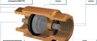
Pipeline network
The product moves between the units of the plant along the pipeline network.
The dairy also has conductive systems for other media - water, steam, cleaning solutions, refrigerant and compressed air. The presence of a wastewater disposal system is also imperative. All these systems do not differ in principle from each other. The only difference is in the materials from which they are made, in the design of the parts and in the dimensions of the pipes.
All parts in contact with the product are made of stainless steel. Other systems use different materials - for example, cast iron, steel, copper, aluminum. Plastics are also used for the manufacture of water and air lines, and ceramics for drainage and waste pipelines.
In this section, we will only talk about the product piping and its parts. Auxiliary piping is described in the section on auxiliary equipment.
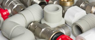
The product piping system includes the following fittings: • Straight pipes, elbows, tees, reducers and couplings
• Special fittings - sight glasses, instrument elbows, etc.
• Valves for stopping and changing direction of flow
• Pressure and flow control valves
• Brackets for pipes.
For hygiene reasons, all parts in contact with the product are made of stainless steel. There are two main grades used: AISI 304 and AISI 316. The latter is often referred to as acid resistant steel. The following grades of Swedish steel correspond (although not completely) to them:
| USA | AISI 304 | AISI 316 | AISI 316L |
| Sweden | SIS 2333 | SIS 2343 | SIS 2359 |
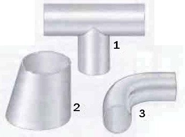
Fig. 1 Some types of fittings that are welded into pipelines. 1 Tees 2 Reducers 3 Elbows
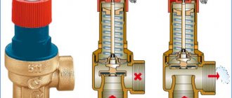
Check valve operation
The check valve very rarely fails prematurely. However, it still has its own lifespan. There can be many reasons for the failure of the valve device. The main causes of wear and failure of the check valve are:
- poor tightness of the blocking element;
- factory defect of the spring;
- excessively high pressure level in the pipes;
- flushing of foreign objects into the sewer;
- improperly designed pipeline;
- blockages and accumulation of dirt, build-up in pipes;
- high groundwater level (in a private house);
- foundation subsidence;
- improper installation (too high or low, sloping).
Any deviation in the operation of the check valve is easy to notice by the external signs of the functioning of the water supply system. The edging in the valve wears out the fastest - by its condition one can judge whether it is worth changing the valve. If there is constant vibration and noise in the system, then the internal spring or shutter is most likely out of order. They can be changed, leaving the old cylinder, however, experts advise in such cases to replace the valve completely.
Thus, the check valve is an important component of the normal functionality of all heating, sewerage and water supply systems. Waste water in a private house should also be discharged through a pipeline with the mandatory installation of a check valve. This inexpensive and reliable plumbing fixture will help make any high pressure water, air, gas or steam system safer and more durable to use. The cost of damage from accidents caused by the lack of a check valve is significantly higher than the price of this device.
Connections
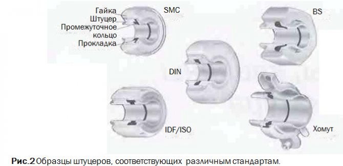
Permanent joints are welded (Fig. 1). There.where undocking is required, the connection is usually made in the form of a threaded nipple, onto which an intermediate ring is put on and a lock nut is screwed on, or as a nipple with an intermediate ring and a clamp (fig. 2).
The presence of a union allows undocking without disturbing other parts of the pipeline. Therefore, this type of fittings is used to connect elements of technological equipment, instruments, etc., which sooner or later have to be removed for cleaning, repair or replacement.
Different countries have different standards for fittings. These standards include SMS (Swedish Standard for Dairy Equipment), which is also internationally recognized, DIN (Germany), BS (England), IDF / ISO * and ISO Clamps (widely used in the USA).
Elbows, tees and similar fittings are available, allowing installation by welding and having places for welding. In the latter case, the fittings can be ordered with a nut or inner part of the connection, or with a tightening connector.
All fittings must be properly sealed to prevent fluid leaks from the system or air being drawn into the system, which will cause problems in the downstream process.
Types and properties
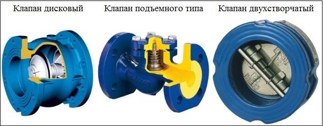
The design of the check valves for the installation of which flanges are used may be different. The choice of a flanged valve with a certain type of shut-off element depends on what tasks such a device is intended for.
So, depending on the design of the shut-off element, they are distinguished:
- rotary valve;
- lift type check valve;
- check valve with ball locking element;
- two-leaf check valve;
- foot check valve equipped with a mesh.
Design of some flanged type check valves
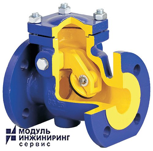
The swing check valve is a locking device, the main part of which is a steel slamming disc, fixed on a spring-loaded axle. At the moment when such a check valve is open, the disc in its inner part is parallel to the movement of the working medium, and when it is closed - perpendicularly. The flanged swing check valve has a simple structure and, accordingly, low cost. If we talk about the disadvantages of this type of check valves, then the most significant of them is that their rotary mechanism at the moment of closing slams the locking disc too much, which eventually leads to wear of the seat. Rotary check valves equipped with a special mechanism that ensure smooth closing of the shut-off disc are devoid of such a drawback. However, such improved flanged rotary valves are more expensive, which somewhat limits their application.
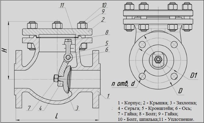
Swing check valve device
In flange-type lift check valves, a special spool is used as a shut-off element, which, under the pressure of the working flow, rises along the vertical axis, and when the pressure decreases, it drops to its seat, blocking the movement of the medium transported through the pipeline. It should be borne in mind that such valves, due to the peculiarities of their design, can only be installed in a vertical position.
Ball check valves, as their name suggests, use a ball-shaped spool as a shut-off element. Their large size does not allow them to be used as interflange locking devices.
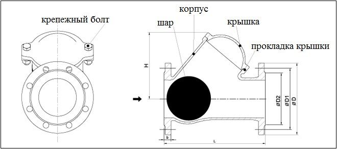
Check valve flanged ball type
The check valve, which is produced mainly in the wafer design, involves the use of two flaps simultaneously in its design.Each of them is connected to a spring, which regulates the force of their resistance to the pressure of the working stream. The wafer-type butterfly valve, due to the small size of its shut-off elements - flaps - is very compact in size.
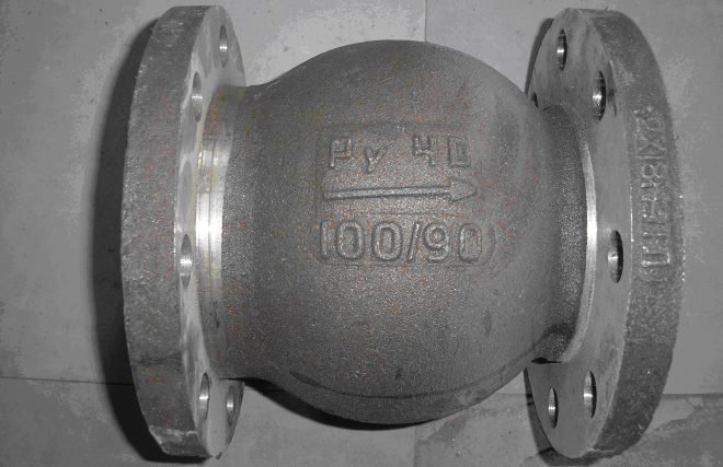
Check valves, the design of which is additionally equipped with a strainer, are used for installation on pipeline systems for pumping oil, gas or water from underground sources. Such devices, the most popular model of which is 16CH42R, simultaneously solve two important problems: their shut-off mechanism does not allow liquid or gas to return back to the source, and the mesh protects the pipeline from large debris entering it.
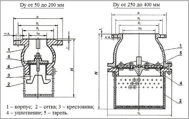
The design of the 16CH42R valve differs depending on the dimensions of the product
Model 16CH42R, the body of which is made of steel or cast iron, is characterized by wide versatility and can be installed on pipelines or pumps used for pumping both liquid and gaseous media.
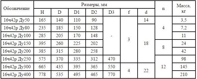
Overall and connecting dimensions of the valve 16h42r
Special fittings
Sight glasses are installed in-line in those places where a visual check of product availability is necessary.
Elbows with fittings for devices are used to install thermometers and manometers. The sensor should be installed upstream to provide the most accurate reading. Special nubs are designed for inserting sampling valves. Instrument connections can also be fitted with special sockets for welding directly to the pipe during installation.
Fig. 3. Sampler.
Fig. 4 Plug for sampling for microbiological analysis.
Sampler
Such fixtures should be installed at strategic points on the production line to sample products for analysis. For quality control purposes, such as determining the fat content of milk or the acidity (pH) level of fermented milk products, samples can be taken using the sampler shown in Figure 3.
When determining the sanitary condition of the production line, the practiced sampling method should completely eliminate the risk of introducing any contamination from the external environment into the pipe. For this purpose, a suction plug is used (see Fig. 4). There is a rubber plug at the bottom of this plug. First, the stopper is removed and all parts of the stopper that could introduce any contamination into the sample are thoroughly disinfected (usually with a swab soaked in a solution containing chlorine just prior to sampling). After that, a needle of a medical syringe is inserted into the product through a rubber plug and a sample is taken with it.
Samples of aseptic products (heat treated at temperatures so high that they are virtually sterile) are always sampled through an aseptic sampling valve to prevent reinfection.
Valves. Valve systems
There are many joints in the pipeline network through which the product flows from one line to another, but which sometimes have to overlap so that two streams of different fluids can move along these two lines without mixing with each other.
When the lines are isolated from each other, any leakage must go to the drain, and any possibility of one liquid entering another must be excluded.
This is a common problem in the design of dairy plants. Dairy products and cleaning solutions are fed through different pipelines and must not touch. Figure 5 shows four possible solutions to this problem.
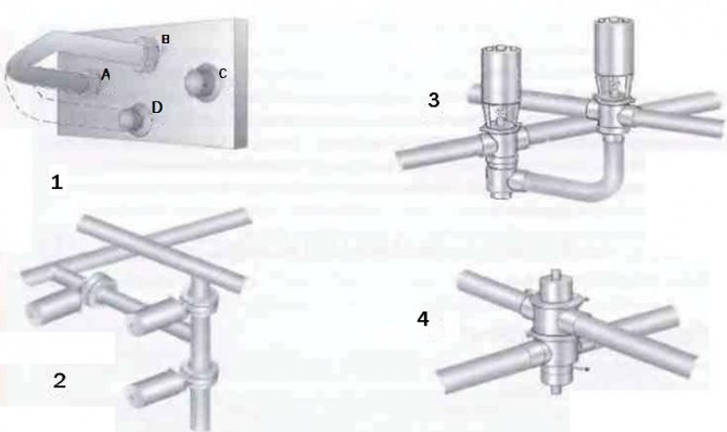
Fig. 5 Mixture valve systems used in the food industry.1 Swivel elbow to manually switch flow to another channel 2 Three shut-off valves can perform the same function 3 One shut-off valve and one change-over valve can do the same job 4 One mixproof valve is sufficient to shut off and change the flow
Globe valves
The valve body has a valve stem seat at the end of the stem. A stem, which is actuated by a crank or pneumatic mechanism, lifts the valve off the seat and lowers it back (see figure 6).
Fig. 6 Manual seated shut-off valve and pneumatic seated changeover valve. The shut-off and changeover valve actuators are interchangeable.
The seated globe valve is also available in a change-over design.
This valve has three to five holes. When the valve is lowered, fluid flows from inlet 2 to outlet 1, and when the valve is raised to the upper seat, flow is directed through outlet 3, as shown in figure 7.
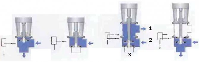
Fig. 7 Shut-off and changeover valves with different core positions and corresponding designations on the process chart.
This type of valve can have up to five holes. Their number is determined by technological requirements.
There are a number of remote controlled actuator options. For example, a valve can be opened with compressed air and closed with a spring, or vice versa. It can also be opened and closed with compressed air (see fig. 8).
Fig. 8 Examples of pneumatic actuators. 1 Valve opens with spring and closes with compressed air 2 Valve closes with spring and opens with compressed air
Actuators are also available for intermediate valve positions and for two-stage opening and closing.
The valve control (fig. 9) is often installed as a block on the valve actuator. This block contains valve position sensors that send information to the main control system. A solenoid valve is built into the air duct to the valve actuator or to the control unit. An electrical signal activates the solenoid valve and allows compressed air to enter the actuator. This causes the valve to open or close as required. When supplied, compressed air passes through the filter, freeing it of oil and other contaminants that can interfere with the proper operation of the valve. When the solenoid valve is turned off, the air supply is cut off and air is removed from the valve on the product pipe, through the outlet in the solenoid valve.
Fig. 9 Valve plug position indicator mounted on the actuator.
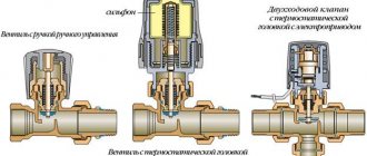
Valve actuators
To control the valves ─ movement of the locking or regulating element ─ various actuators are used: manual, electric, electromagnetic, hydraulic, pneumatic, or their combinations.
Examples of a combined drive are a pneumatic hydraulic drive using compressed gas and hydraulic power and an electro-hydraulic drive.
The transfer of translational force from the drive to the locking or regulating element is carried out by means of a rod (spindle).
Electric actuators are widely used to control control valves in heating, ventilation and air conditioning systems. A modern electric drive is a complex technical device that includes a control system, an electric motor and a gearbox.
If in an electric drive, electrical energy is used "directly", then in an electromagnetic drive, its transformation into mechanical energy occurs as a result of the interaction of an electromagnetic field and a core made of ferromagnetic material.
A solenoid valve equipped with an integral or remote solenoid actuator is a common design.
Solenoid valves can be operated from alternating current from centralized electrical networks or from direct current from autonomous sources ─ batteries or direct current generators.
Solenoid valves are widely used in instrumentation; to control the processes of dosing, shutdown, mixing, dumping, distribution of flows of working media.
For many years, pneumatic actuators have been used to control valves, applicable to almost all but the largest valve sizes, where a high-torque hydraulic actuator comes to the rescue.
The use of actuators makes it possible to automate the operation of the valves. Requirements for valve actuators: guarantee of the required operating range values (output torque), wear resistance, tightness, compliance with safety requirements, corrosion resistance.
Gate valves
The gate valve (in Fig. 10) is a shut-off valve. For switching operation, two valves must be used.
Gate valves are often used when working with products that are susceptible to mechanical stress - yoghurt and other fermented milk products, since the hydraulic resistance of the valve is small, and, therefore, the pressure drop across the valve and turbulence are negligible. These valves are very good for high viscosity products and as a straight-through valve they can be installed on straight pipe runs.
A valve of this type usually consists of two identical flaps, between which an o-ring is installed. A streamlined disc is located in the center of the valve. It usually rests on bushings to keep the stem from rubbing against the valve body.
When the disc is in the open position, the valve offers very little flow resistance. In the closed position, the disc is sealed with a rubber ring.
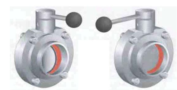
Fig. 10 Manual gate valve in open (left) and closed (right) position.
Introduction. Hydraulic drive composition
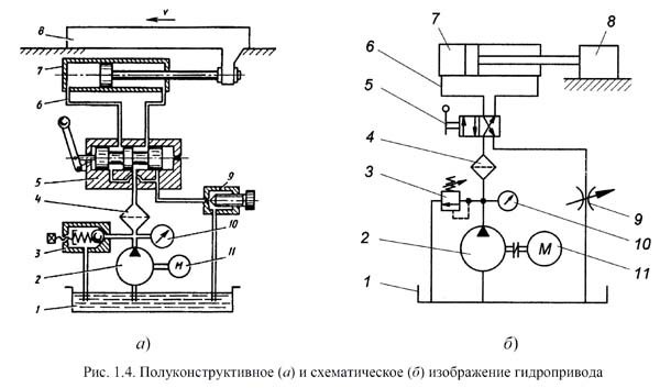
Semi-constructive (a) and schematic (b) images of a hydraulic drive
In its most general form, a hydraulic drive consists of a source of hydraulic energy - a pump, a hydraulic motor and a connecting line (pipeline).
In the hydraulic diagram fig. 1.4 semi-structurally (a) and schematically (b) shows the simplest hydraulic drive, in which pump 2, driven by an electric motor 11, sucks in working fluid from tank 1 and through filter 4 supplies it to the hydraulic system, and the maximum pressure is limited by the adjustable spring force of the safety valve 3 (controlled pressure gauge 10). To avoid accelerated wear or breakage, the setting pressure of the safety valve must not be higher than the rated pressure of the pump.
Depending on the position of the distributor handle 5, the working fluid through pipelines (hydraulic lines) 6 enters one of the chambers (piston or rod) of the cylinder 7, forcing its piston to move together with the rod and the working member 8 at a speed v, and the liquid from the opposite chamber through the distributor 5 and an adjustable resistance (choke) 9 is displaced into the tank.
With a fully open throttle and an insignificant load on the working body, all the working fluid supplied by the pump enters the cylinder, the speed is maximum, and the value of the working pressure depends on the losses in the filter 4, devices 5 and 9, cylinder 7 and hydraulic lines 6. Covering the throttle 9, the speed can be reduced until the working body comes to a complete stop. In this case (as well as when the piston rests on the cylinder cover or an excessive increase in the load on the working element), the pressure in the hydraulic system rises, the ball of the safety valve 3, compressing the spring, moves away from the seat and the working fluid supplied by the pump (pump flow) is partially or completely bypassed through safety valve into the tank under the maximum working pressure.
During prolonged operation in the bypass mode, due to large power losses, the working fluid in the tank quickly heats up.
The hydraulic diagram shows in the form of designations:
- hydraulic power source - - pump 2;
- hydraulic motor - cylinder 7;
- hydraulic guide equipment - distributor 5;
- hydraulic control equipment - valve 3 and throttle 9;
- control devices - pressure gauge 10;
- reservoir for working fluid - tank 1;
- working environment air conditioner - filter 4;
- pipelines — 6.
Hydraulic drives of stationary machines are classified according to pressure, control method, type of circulation, control and monitoring methods.
Automatic control
An air drive is used for automatic control of the slide gate (Fig. 11). The following operating modes are possible:
• Spring to close / air to open (valve closed in neutral position)
• Spring open / air close (valve open in neutral position)
• Air opening and closing.
The disc rotates easily until it touches the O-ring. Further, more force is required to compress the rubber. A conventional spring-type actuator produces maximum force at the start of travel when minimum force is required,
and at the end of the stroke, when the effort should be greater, it just weakens. Therefore, it is preferable to use drives that provide the required force at every moment of operation.
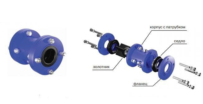
Another type of gate valve is a flanged valve (see fig. 12).
In fact, it is similar to the already described type of gate valve, but differs in that it is fixed between two flanges welded to the pipeline. It functions in the same way as a conventional gate valve. During operation, it is screwed to the flanges. During maintenance, the screws are loosened and the valve can be easily removed for work.
Fig. 11 The principle of operation of the air drive of the slide damper.
Fig. 13 Two-seat plug-in, balanced-plug valve with integral movable seat. 1 Actuator 2 Upper port 3 Upper plug 4 Drain chamber 5 Hollow shaft connecting to atmosphere 6 Lower port 7 Bottom plug with balance
Check valve classification
In order to know exactly which reverse-acting valve should be installed in the domestic plumbing, you should familiarize yourself with the wide range of these products on the market today. The main types of check valves:
- flanged - in its design, it has side flange mountings and is designed for installation in horizontal and corner water pipelines;
- ball - the shutter element of such a valve is made not in the form of a plate, but in the form of a ball. Such a valve has the ability to control the amount of water entering the system and is used in household plumbing;
- disc - often, these are large types of check-type valves with a shutter element in the form of a disc on a rubberized base. They are used in automatic sewerage and water supply systems for industrial use. Adjustable by external mechanical force;
- cracker - a specific check valve, which has a saddle axis and a slamming angle shutter in its design. It is used in complex automatic water supply systems;
- wafer - lightweight and minimal in size valve, characterized by the presence of flange fasteners to the pipeline nozzles. Easy to install, easy replacement and long-term system operation.
The above classification of check valves has certain differences associated with the design, device, and installation of individual models. Almost all valve options are suitable for domestic use, but the most popular are flanged and wafer mechanisms.
Mixproof valves
Valves of this type (fig. 13) can be single or double-seated, but here we will talk about the double-seated option (fig. 13) as more typical for this type of valve.
The double-seat valve has two independent seats with a drainage chamber between them.This chamber must be vented to the atmosphere to provide complete guarantees against mixing flows - in the event of a leakage of one of the seats. When the double seat valve is commanded to operate, the chamber between its upper and lower bodies is closed, then the valve opens, connecting the upper and lower pipelines. When the valve is closed, first the upper valve plug cuts off the liquid supply from the upper pipeline, and then the drainage chamber communicates with the atmosphere. This does not result in any significant product loss during operation.
It is important that the lower plug is hydraulically balanced to avoid opening the valve and subsequent mixing of fluids as a result of water hammer.
During washing, one of the valve closures opens or an external CIP line is connected to the drain chamber. Some valves can be connected to an external source to clean those parts of the valve that have been in contact with the product.
A single seat non-mixing valve has one or two seats, but for the same plug. The space between the two cores communicates with the atmosphere. Before this valve starts to operate, this drainage chamber is closed by small check valves. When flushing is required, an external CIP line is connected to the drain chamber through these valves.
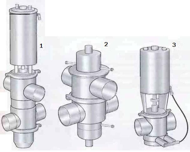
Fig. 14 Three types of non-mixing valves. 1 Double-seat valve with a washer for a movable seat 2 Double-seat valve with an external wash 3 Single-seat valve with an external wash
Features and applications of check valves
Check valves of various types (including flanged ones) are used to protect the pipeline from:
- the occurrence of reverse flows of the working environment in it;
- hydraulic shocks.
Reverse flow in pipelines, as is clear from its name, is the movement of the working medium in the opposite direction. This can happen, in particular, when the pump, which provides the supply of the working medium and its movement, is turned off. If for heating systems such a phenomenon as a reverse flow is not particularly critical, then in sewage and water supply systems, as well as in pipelines through which oil products and other media are transported, it cannot be allowed to occur. That is why the use of check valves in such pipeline systems is a must.
Check valve flanged stainless steel, designed for use in the environment of petroleum products
Another undesirable phenomenon, from the consequences of which pipeline systems can be protected by a flanged, wafer-type or any other valve, is water hammer. It is characterized by the fact that a sharp drop in the pressure of the transported medium occurs in the pipeline, which leads to the formation of a shock wave passing along the entire length of the pipeline system.
Water hammer can eventually lead to the destruction of individual sections of the pipeline and the failure of the elements that are used to ensure its normal operation. With the help of check valves, installed by means of flanges or in any other way, the system is divided into separate isolated sectors, which makes it possible to effectively protect it from the effects of a water hammer.
Feedback and valve control
Position indication
Various types of instruments can be installed on the valve, showing its position (see Fig. 15), depending on the control system of the entire complex. This includes microswitches, inductive proximity switches, Hall sensors. These switches send feedback signals to the control system.
When only switches are installed on the valves, it is necessary for each valve to have a corresponding solenoid valve in the wall-mounted solenoid valve cabinet. When a signal is received, the solenoid valve directs compressed air to the valve installed in the pipeline, and when the signal is interrupted, the solenoid valve stops the air supply.
In such a system (1), each valve is supplied with an individual electrical cable and its own air hose.
The combination unit (2) is usually mounted on the valve actuator. It includes the same position sensors as the above, and the solenoid valve is installed along with the sensors. This means that one air hose can supply air to several valves, but each valve still needs a separate cable.
Fig. 15 Valve position indication systems. 1 Only sensors 2 Combination unit on the valve actuator 3 Display and control system
Valve designs
The general principle of the valve arrangement is the same - the movement of the moving parts of the shutter relative to the stationary ones leads to a change in the flow area, and, therefore, to a change in the throughput. But the valve closure device is different.
For example, the movable element of the shutter ─ the spool ─ can be needle (in the form of a narrow cone), piston (cylindrical), spherical, poppet.
Sometimes a reference to the type of movable valve element appears in the valve name. For example, a needle valve or a piston valve.
The needle valve offers high performance and efficient flow control.
In a safety piston valve, the piston is a sensitive element that senses the effect of the pressure of the working medium.
In a cage control valve, the shutter is a stationary part called a cage because of the large number of profiled holes that serve to pass the working fluid. A plunger moving inside the cage, changing the area of their open sections, regulates the throughput of the valve.
By the number of seats, single-seat and double-seat valves are distinguished, when two seats are on the same axis.
If the flow area of the valve is formed by two or more gates in series, it is called a multi-stage valve.
By the type of seal that ensures the required tightness of the valve connections relative to the external environment, it is possible to note stuffing box and bellows valves. In a safety bellows valve, the bellows serves not only to seal the stem, but also serves as a sensitive or force element. Bellows seals are used in many valves: shut-off, control, safety.
According to the mode of action, the valves can be normally closed (NC valve) and normally open (NO valve). In the absence or cessation of energy supply, which creates a force to move the locking (regulating) element, the NC valves automatically provide the “closed” position, and the NO valves, under the same conditions, provide the “open” position.
Full control
It is carried out using the position sensor unit shown in Fig. 9, which is specially designed for computer control. This unit includes a position indicator, a solenoid valve and an electronic device that can control up to 120 valves with just one cable and one air hose (item 3 in Figure 15). This unit can be centrally programmed and is inexpensive to install.
Some systems may also, without receiving external signals, open valves to flush the seats. They can also count the number of valve strokes.
This information can be used to plan service activities.
The composition of the hydraulic drive on the example of the power head of the modular machine tool
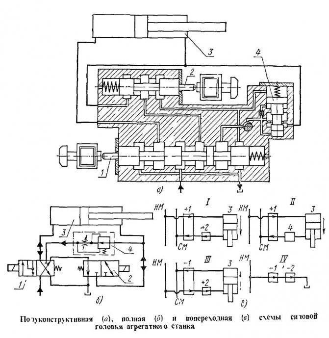
Powerhead hydraulic system of powerhead machine
Depending on the method of depicting mechanisms and equipment on schematic diagrams, they can be semi-constructive, full and transverse.
The hydraulic system of any variant has at least two main lines - pressure and drain. Targeted routes are connected to them, which connect hydraulic motors of one action or another with the highways. Distinguish routes: initial, free movement, precise movement, unregulated movement, control and blocking.
In fig. 244 shows a semi-structural, complete and transverse diagrams of the power head of a modular machine tool, which performs three transitions per cycle of work: fast approach, working stroke and fast retraction. On the semi-structural diagram (Fig. 244, a), during the transition "Fast feed", both spools are displaced by pushing electromagnets: the main spool 1 to the right, and the spool 2 of rapid moves to the left. In this position, the oil from the pump through the first left neck of the spool 1 enters the external cavity of the cylinder 5, and from the opposite cavity of the same cylinder through the neck of the spool 2 and the second neck of the spool 1 is sent to the tank.
At the transition "Working stroke", the spool electromagnet 2 is turned off, which forces the oil from the rod end of the cylinder 3 to drain through the speed regulator 4 and then through the third neck of spool 1 into the tank.
During the transition "Fast retraction", the spool 1 electromagnet is turned off, and the spool 2 electromagnet is turned on again, and this changes the direction of oil flow: from the pump through the second spool neck 1 to the rod cavity of the cylinder, and from the opposite cavity through the first spool neck 1 to the tank. In the "Stop" position, both electromagnets are disconnected, the spools become in the position shown in the diagram, and the pressure line from the pump through the second neck of the spool 1, the neck of the spool 2 and the annular groove around the rightmost drum of the spool 1 is connected to the tank.
In the complete schematic diagram (Fig. 244, b), all elements of the hydraulic system have designations similar to the semi-structural diagram, therefore, the above description of the operation of the hydraulic drive can be used in this case. Comparing the diagrams, you can see that the design of the second diagram is simpler, and, in addition, it clearly shows the function of the spools at their different positions.
On the transverse diagrams (Fig. 244, e), the same elements are shown, and, in addition, the signs "+" and "-" and arrows of various lengths make it possible to clarify the actions of the electromagnets and the power cylinder. In fact, from the consideration of scheme 1 it follows that both electromagnets are connected, and oil from the pressure line NM through one neck of the spool 1 enters the external cavity of the cylinder 3, and from the opposite cavity it strips off through the necks of the spool 2 and 1. The piston moves in the direction " Stem forward ”accelerated (long arrow).
From scheme II it follows that in this transition only spool 1 works, which remains in the same position, and the shutdown of the spool 2 of rapid moves connects the speed controller 4, consisting of a pressure reducing valve and a throttle. The piston at this transition moves in the same direction, but at a working speed (short arrow). Diagram III shows that spool 2 is turned on again, and spool 1 is turned off, but it takes part in this transition. With this switching of the spools, the oil from the NM line through the necks of both spools enters the rod cavity of the cylinder, and from the opposite cavity it is drained through the second neck of the spool 1. The piston changes its speed and direction. From scheme IV it follows that both spools are disabled, and the pressure line is connected to the tank through their necks, and therefore, in this position, even when the pump is running, the hydraulic drive is turned off.
Control valves
Shut-off and diverter valves are simple - they or
open, or closed. For a control valve, the orifice diameter can change gradually. This valve is designed to accurately control flow and pressure at various points in the system.
Pressure reducing valve (in Fig. 17) maintains the required pressure in the system. If it drops, the spring presses the valve against the seat. As soon as the pressure rises to a certain level, the pressure on the valve plug overpowers the spring and the valve opens. By adjusting the spring tension, the valve can be opened at a certain hydraulic pressure.
Manual control valve (fig. 18) has a special shaped plug stem.
Turning the adjusting knob moves the valve up or down, decreasing or increasing the passage and therefore the flow rate or pressure. The valve has a graduated scale.
Fig. 19 Valve with pneumatic flow control.
Fig. 20 Constant pressure valve.
Fig. 21 Principle of operation of a constant pressure valve when regulating the pressure upstream of the valve. 1 Equilibrium between air and product 2 Product pressure decreases, the valve closes and the product pressure rises again, rising to the set level 3 Product pressure rises, the valve opens, and the product pressure drops to the set level
Fig. 22 Constant pressure valve with booster pump to regulate product pressure that exceeds the actual compressed air pressure
Pneumatic control valve (fig. 19) functions in the same way as described above. The valve-seat assembly is also similar to a manual valve. As the valve is lowered towards the seat, the flow path gradually narrows.
This type of valve is designed to automatically regulate pressure, flow and level during the process. A sensor is built into the production line that continuously reports the values of the measured parameter to the control device, which makes the necessary adjustments to the gate position in order to maintain the set value.
Constant pressure valve - one of the most commonly used (fig. 20). The compressed air is fed through a pressure reducing valve into the space above the diaphragm. The air pressure is changed by the pressure reducing valve until the product pressure gauge shows the required value. The target product pressure is then kept constant regardless of changes in operating conditions. The principle of operation of a constant pressure valve is shown in figure 21.
The valve responds instantly to changes in product pressure. Decreased product pressure results in an increased force on the diaphragm on the air pressure side, which
remains constant. The valve plug is then moved downward with the diaphragm, the flow is limited and the product pressure is increased to a predetermined level.
The increased pressure of the product causes the effect it exerts on the diaphragm to exceed the pressure of the compressed air from above. In this case, the shutter is pushed upward, increasing the diameter of the channel through which the product passes. The flow rate will increase until the product pressure drops to a predetermined level.
This valve is available in two versions - to maintain a constant pressure upstream or downstream of the valve. The valve cannot regulate the product pressure if the available air pressure is lower than the required product pressure. In such cases, a booster pump can be installed above the valve, and then the valve can operate at product pressures of double the actual compressed air pressure.
Valves providing constant upstream pressure are often installed after separators and pasteurizers. And those that maintain a constant outlet pressure are used in the lines in front of the packaging machines.
Varieties of valves
Shut-off valves
Shut-off valves are one of the most commonly used types of pipeline fittings. The device is built on a locking mechanism moving reciprocally parallel to the axis of the water flow. The most famous name given to stop valves is a valve, but in reality, in accordance with GOST 24856-81, the use of the name "valve" is not considered correct.
Shut-off valves are made of metals such as cast iron, brass, bronze, aluminum, titanium and non-metallic alloys. The valve mechanism can be angular, straight-through and needle-like.
A big advantage of this type of shut-off valve is a small, compared to other types of shutter stroke, which is required to fully open the shut-off mechanism.
For this purpose, it is enough to raise the valve plate by 1/4 of the diameter of the hole in the seat. But in order to open the valve, the wedge or disc is moved by an amount equal to the diameter of the hole. This explains the fact that shut-off valves are produced with a significantly lower height than a valve with the same passage diameter. But its headroom is greater than that of the gate valve.
Swing check valves
Swing check valves; devices with a reverse rotary design operate in an automatic mode and are designed to prevent the backflow of the working medium in the pipeline. Swing check valves have two designs: lift and rotary. The valves consist of a disc that produces a reciprocating motion. Swing check valves are equipped with a special shutter that rotates around the axis in the horizontal direction. The axle is located in the center of the seat and piping mechanism.
On a pipeline having a horizontal direction, check valves are placed in the position with the lid up. On a pipeline with a vertical direction, the fittings are positioned in accordance with the direction of the arrow upwards. The medium flow in the pipeline must be directed under the flapping disc. Check valves have the following technical data:
DN - from 15 to 2200 mm; PN - from 2.5 to 250 kgf / cm2; The temperature of the working medium should be up to 600 ° C.
Shut-off valves
Shut-off valves belong to the category of shut-off devices. Its main indicator is the instantaneous response. It is used when a piping system requires a device that is able to provide a minimum length of time during the opening and closing process. For these purposes, electro-pneumatic or electromagnetic drives are mounted in the shut-off valves.
Safety valves
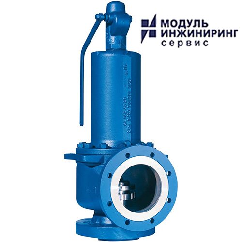
Safety valves are designed for the pipeline system. It serves as a reliable protection against the destruction of the mechanical nature of the destruction of vessels and pipelines in which there is increased pressure. Safety valves operate by automated release of excess liquid, vapors and gases from pipes at an excessive pressure level. After the medium is released, the pressure indicator drops to a mark lower than when the valve began to respond. The safety valves operate automatically and remain in the closed position until the pressure in the system increases excessively.
The technical characteristics of this type include the response pressure and its throughput, that is, the amount of medium that is released over a certain time when the valve is in the open position.
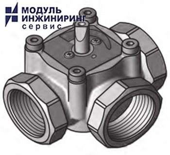
Distribution valves
Distribution valves direct the working medium into one or more pipelines. Distribution valves are divided into categories based on the number of branch pipes in their scheme.Distribution valves are three-way (with three nozzles), four-way (with four nozzles) and multi-way.
Most often, control solenoid valves are used to control pneumatic drives and hydraulic drives. It is also used to take air samples from multiple chambers. When operating in a pneumatic actuator, the exhaust air can be discharged directly into the atmosphere or into a container. After the control medium has applied pressure to the cylinder, it must be fixed. This operation is performed by means of an electromagnetic drive without or with a latch, which fixes the position of the spool in the desired position. Reverse designs are also applicable.
Mixing valves
Mixing valves are designed to mix different media in the right proportions. For example, mix a cold and hot stream of water, while the temperature of the mixture remains at a certain level. Or by changing the temperature according to the required parameters. Mixing valves belong to the category of regulating devices. In mixing valves, the command signal, which is responsible for the position of the plunger, determines the parallel flow of two media. In valves with modulating design, the position of the plunger determines the consumption of only one medium. Mixing valves are controlled by means of a pneumatic actuator (MIM) or an electric actuator (EIM).
Electromagnetic valves
Solenoid valves are of two types: with a direct and indirect principle of operation. By means of a direct-acting solenoid valve, the valves are opened or closed by means of a moving core when the coil of the solenoid valve is energized.
Solenoid valves, operating on the basis of indirect action, function by feeding the coil of the replacement valve. And the main valve is opened by the action of pressure from the medium and its compensation with minimal mechanical effort. Electromagnetic valves with an indirect action mechanism use the energy of the working medium that passes through the valve. Therefore, they have a much larger list of operating pressures, as well as a larger number of nominal diameters and solenoids of a relatively low power level.
For reliable operation, as a rule, electromagnetic valves are chosen, it is better to choose a valve model with direct action, which does not react so well to air purity, ambient temperature and has more accurate actuation and durability in operation. Electromagnetic valves have a big plus - quick response.
Yusuf Bulgari
Valve systems
In order to minimize the number of dead ends and to be able to distribute the product between different areas of the dairy, the valves are grouped into blocks. Valves also isolate individual lines so that one line can be flushed while other lines circulate product.
There must always be an open drain hole between the product and cleaning solution flows, as well as between the product flows.
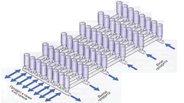
Fig. 23 Valve comb serving tanks. The valves on the tank site are located in such a way that the flows of product and cleaning solutions entering and leaving the tanks do not intersect
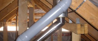
Pipe brackets
The pipelines are laid two to three meters above the floor of the dairy. All units and parts of the pipeline must be easily accessible for inspection and maintenance. The piping should be slightly sloped (1: 200-1: 1000) to ensure self-draining. There should be no "bags" along the entire length of the pipelines so that product or cleaning solution does not accumulate there.
The pipes must be securely fastened.On the other hand, the fastening of the pipes should not be too rigid to exclude any displacement. At high temperatures of the product or cleaning solution, the pipes undergo significant expansion. The resulting elongation and torsional loads in bends and in the equipment must be compensated in a certain way. This circumstance, as well as the fact that various assemblies and details make the pipeline system heavier to a large extent, require high accuracy of calculations and high professionalism from the designers.
Fig. 24 Example of standard pipe supports.