Here you will find out:
- When you need a controller
- Solar controller functions
- How the Battery Charge Controller Works
- Device characteristics
- Types
- Selection options
- Ways to connect controllers
- Homemade controller: features, accessories
- How can I replace some components
- Principle of operation
The solar battery charge controller is a mandatory element of the power system on solar panels, except for the batteries and the panels themselves. What is he responsible for and how to make it yourself?
When you need a controller
Solar energy is still limited (at the household level) to the creation of photovoltaic panels of relatively low power. But regardless of the design of the solar-to-current photoelectric converter, this device is equipped with a module called a solar battery charge controller.
Indeed, the solar light photosynthesis setup includes a rechargeable battery that stores the energy received from the solar panel. It is this secondary energy source that is primarily serviced by the controller.
Next, we will understand the device and the principles of operation of this device, and also talk about how to connect it.
With the maximum battery charge, the controller will regulate the current supply to it, reducing it to the required amount of compensation for the self-discharge of the device. If the battery is completely discharged, the controller will disconnect any incoming load to the device.
The need for this device can be boiled down to the following points:
- Multi-stage battery charging;
- Adjustment of turning on / off the battery when charging / discharging the device;
- Battery connection at maximum charge;
- Connecting charging from photocells in automatic mode.
The battery charge controller for solar devices is important in that performing all of its functions in good condition greatly increases the life of the built-in battery.
Where is installed
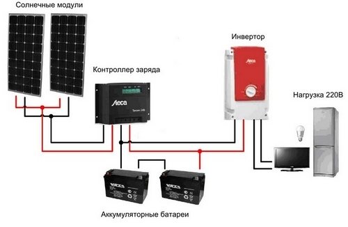
The controller is connected between the battery and the solar panel. However, a solar inverter must be included in the wiring diagram. The inverter is used to convert the 12 V DC current from the solar panel to the 220 V AC current from any outlet in the house, mounted after the battery.
It is also important to have a fuse that performs a protective function against various overloads and short circuits. Therefore, in order to secure your home, you need to install a fuse. In the presence of a large number of solar panels, it is desirable to install fuses between each element of the circuit.
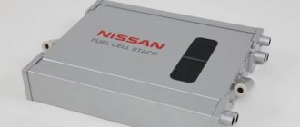
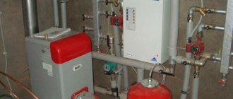
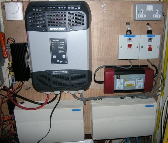
The picture below shows what the inverter looks like (black box):
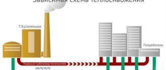
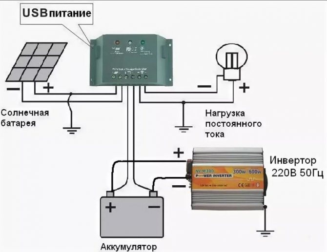
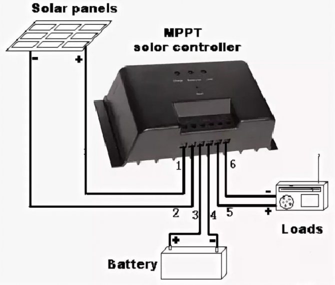
The standard connection diagram looks something like the one shown in the figure below.
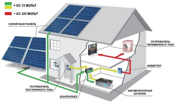
The diagram shows that the solar panels are connected to the controller, electrical energy is fed to the controller and then stored in the battery. From the battery, it goes back to the controller, and then goes to the inverter. And after the inverter, there is a distribution for consumption.
Solar controller functions
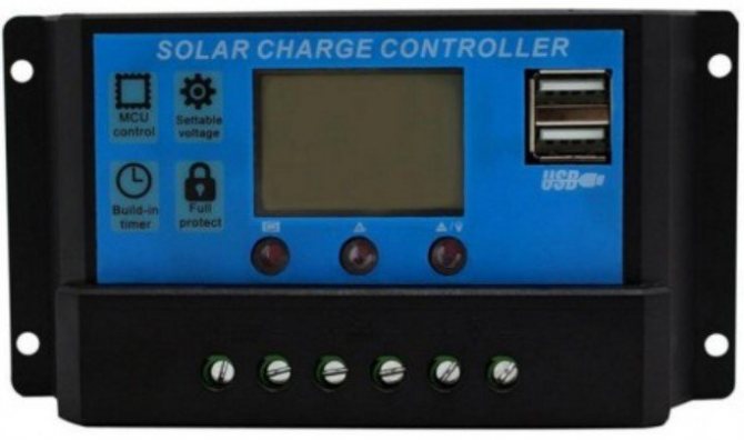
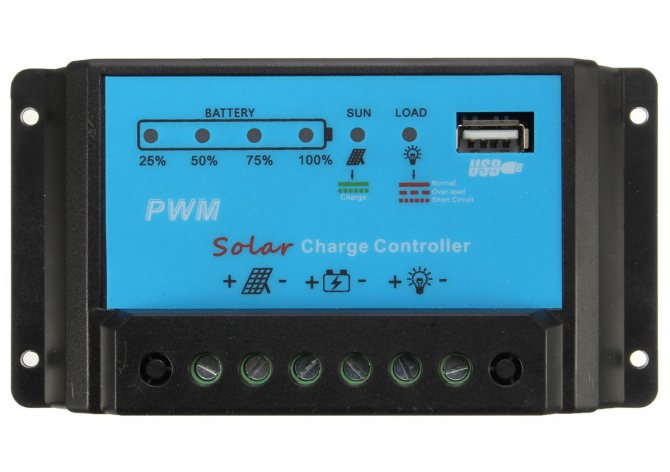
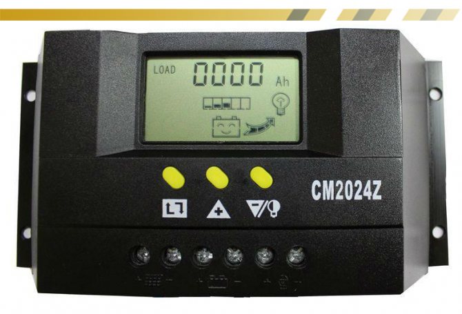
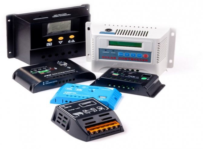
The electronic module, called the solar battery controller, is designed to perform a variety of monitoring functions during the charging / discharging process of the solar battery.
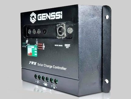
This looks like one of the many existing models of charge controllers for solar panels. This module belongs to the development of the PWM type
When sunlight falls on the surface of a solar panel installed, for example, on the roof of a house, the photocells of the device convert this light into electric current.
The resulting energy, in fact, could be fed directly to the storage battery. However, the process of charging / discharging the battery has its own subtleties (certain levels of currents and voltages). If you neglect these subtleties, the battery will simply fail in a short period of time.
In order not to have such sad consequences, a module called a charge controller for a solar battery is designed.
In addition to monitoring the battery charge level, the module also monitors energy consumption. Depending on the degree of discharge, the battery charge controller circuit from the solar battery regulates and sets the level of current required for the initial and subsequent charging.
Depending on the capacity of the solar battery charge controller, the designs of these devices can have very different configurations.
In general, in simple terms, the module provides a carefree "life" for the battery, which periodically accumulates and releases energy to consumer devices.

What happens if you do not install
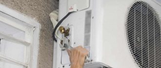
If you do not install MPPT or PWM controllers for solar panels, then you will need to independently monitor the voltage level on the batteries. This can be done using a voltmeter, as shown in the figure below.
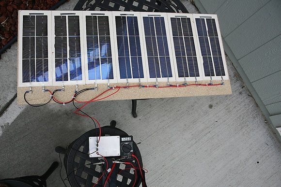
However, with such a connection, the battery charge level will not be fixed, as a result of which it may burn out and fail. This connection method is possible when connecting small solar panels to power devices with a power of no more than 0.1 kW. For panels that will power an entire house, installation without a controller is not recommended, since the equipment will fail much earlier. Also, due to overcharging of the battery, they may fail: the inverter, since it will not cope with such a voltage, may burn out the wiring from this, and so on. Therefore, correct installation should be carried out, all factors should be taken into account.
How the Battery Charge Controller Works
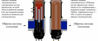
In the absence of sunlight on the photocells of the structure, it is in sleep mode. After the rays appear on the elements, the controller is still in sleep mode. It turns on only if the stored energy from the sun reaches 10 volts in electrical equivalent.
As soon as the voltage reaches this indicator, the device will turn on and through the Schottky diode will begin to supply current to the battery. The battery charging process in this mode will continue until the voltage received by the controller reaches 14 V. If this happens, then some changes will occur in the controller circuit for a 35 watt solar battery or any other. The amplifier will open access to the MOSFET, and the other two, weaker ones, will be closed.
This will stop charging the battery. As soon as the voltage drops, the circuit will return to its original position and charging will continue. The time allotted for this operation to the controller is about 3 seconds.
DIY charge controller
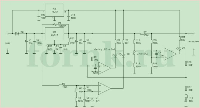
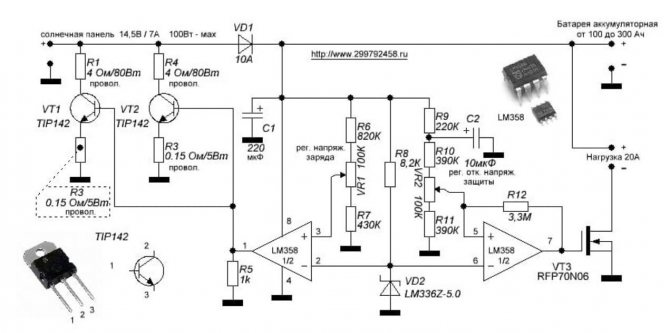
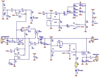
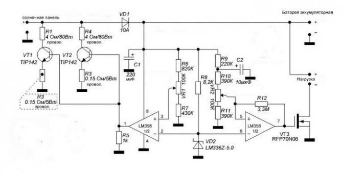
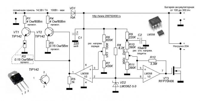
If you have experience in working with electrical equipment, you can create a controller for charging a solar battery yourself. The picture below shows the simplest diagram of such a device.
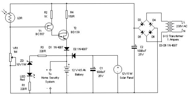
Let's consider the principle of operation of such a scheme. An LDR photocell or photoresistor is a device that changes its resistance when light hits it, that is, it is a solar panel. Controlled by transistors. During exposure to the sun, the transistors are closed. The current is transmitted from the panel to the battery through the diode D2, it is needed here so that the current does not flow in the other direction.When fully charged, the ZD regulator sends a signal to the LED red lamp, which lights up red, and charging stops. When the voltage on the battery decreases, the stabilizer turns off and charging takes place. Resistors are necessary in order to reduce the amperage so that the elements do not fail. The diagram also indicates a transformer, from which charging can also occur, the principle is the same. A current begins to flow along this branch at night or in cloudy weather.
Device characteristics
Low power consumption when idle. The circuit was designed for small to medium sized lead acid batteries and draws a low current (5mA) when idle. This extends the battery life.
Readily available components. The device uses conventional components (not SMD) that can be easily found in stores. Nothing needs to be flashed, the only thing you need is a voltmeter and an adjustable power supply to tune the circuit.
The latest version of the device. This is the third version of the device, so most of the errors and shortcomings that were present in the previous versions of the charger have been corrected.
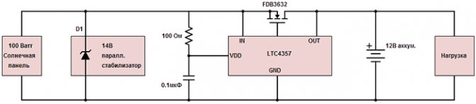
Voltage regulation. The device uses a parallel voltage regulator so that the battery voltage does not exceed the norm, usually 13.8 Volts.
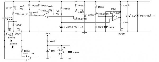
Undervoltage protection. Most solar chargers use a Schottky diode to protect against battery leakage to the solar panel. A shunt voltage regulator is used when the battery is fully charged. One of the problems with this approach is diode losses and, as a consequence, its heating. For example, a solar panel of 100 watts, 12V, supplies 8A to the battery, the voltage drop across the Schottky diode will be 0.4V, i.e. the power dissipation is about 3.2 watts. This is, firstly, losses, and secondly, the diode will need a radiator to remove heat. The problem is that it will not work to reduce the voltage drop, several diodes connected in parallel will reduce the current, but the voltage drop will remain that way. In the diagram below, instead of conventional diodes, mosfets are used, therefore power is lost only for active resistance (resistive losses).
For comparison, in a 100 W panel when using IRFZ48 (KP741A) mosfets, the power loss is only 0.5 W (at Q2). This means less heat and more energy for the batteries. Another important point is that mosfets have a positive temperature coefficient and can be connected in parallel to reduce on resistance.
The above diagram uses a couple of non-standard solutions.
Charging. No diode is used between the solar panel and the load, instead there is a Q2 mosfet. A diode in the mosfet allows current to flow from the panel to the load. If a significant voltage appears on Q2, then the transistor Q3 opens, the capacitor C4 is charged, which forces the op-amp U2c and U3b to open the mosfet of Q2. Now, the voltage drop is calculated according to Ohm's law, i.e. I * R, and it is much less than if there was a diode there. Capacitor C4 is periodically discharged through resistor R7 and Q2 closes. If a current flows from the panel, then the self-induction EMF of the inductor L1 immediately forces Q3 to open. This happens very often (many times per second). In the case when the current goes to the solar panel, Q2 closes, but Q3 does not open, because diode D2 limits the self-induction EMF of the choke L1. Diode D2 can be rated for 1A current, but during testing it turned out that such a current rarely occurs.
The VR1 trimmer sets the maximum voltage. When the voltage exceeds 13.8V, the operational amplifier U2d opens the mosfet of Q1 and the output from the panel is "short-circuited" to ground.In addition, the U3b opamp turns off Q2 and so on. the panel is disconnected from the load. This is necessary because Q1, in addition to the solar panel, "short-circuits" the load and the battery.
Management of N-channel mosfets. The mosfets Q2 and Q4 require more voltage to drive than those used in the circuit. To do this, the op-amp U2 with a strapping of diodes and capacitors creates an increased voltage VH. This voltage is used to power U3, the output of which will be overvoltage. A bunch of U2b and D10 ensure the stability of the output voltage at 24 volts. With this voltage, there will be a voltage of at least 10V through the gate-source of the transistor, so the heat generation will be small. Usually, N-channel mosfets have much lower impedance than P-channel ones, which is why they were used in this circuit.
Undervoltage protection. Mosfet Q4, U3a opamp with external strapping of resistors and capacitors, are designed for undervoltage protection. Here Q4 is used non-standard. The mosfet diode provides a constant flow of current into the battery. When the voltage is above the specified minimum, the mosfet is open, allowing a small voltage drop when charging the battery, but more importantly, it allows current from the battery to flow to the load if the solar cell cannot provide sufficient output power. A fuse protects against short-circuits on the load side.
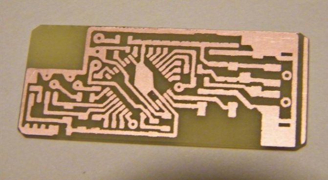
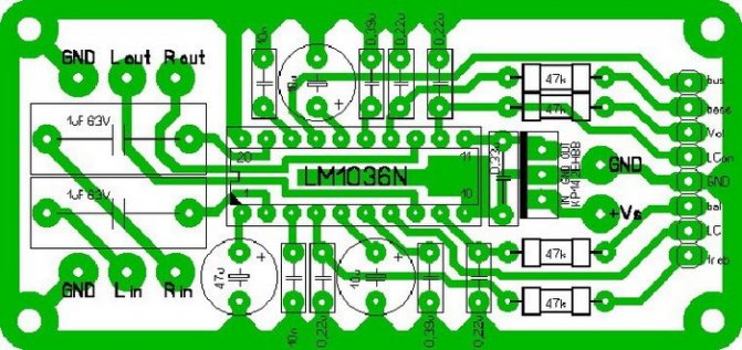
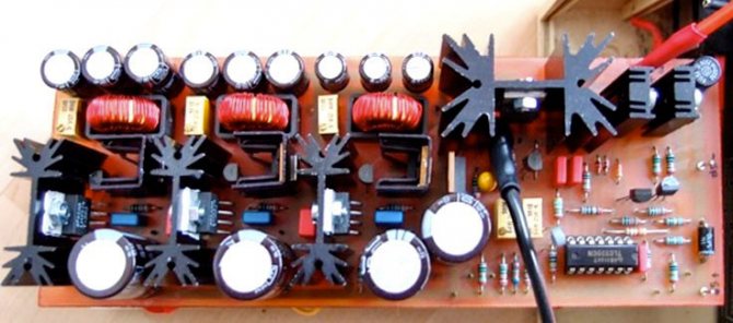
Below are pictures of the arrangement of elements and printed circuit boards.
Setting up the device. During normal use of the device, jumper J1 must not be inserted! The D11 LED is used for setting. To configure the device, connect an adjustable power supply to the “load” terminals.
Setting undervoltage protection Insert jumper J1. In the power supply, set the output voltage to 10.5V. Turn trimmer VR2 counterclockwise until LED D11 lights up. Turn VR2 slightly clockwise until the LED turns off. Remove jumper J1.
Setting the maximum voltage In the power supply, set the output voltage to 13.8V. Turn trimmer VR1 clockwise until LED D9 turns off. Turn VR1 slowly counterclockwise until LED D9 lights up.
The controller is configured. Don't forget to remove jumper J1!
If the capacity of the entire system is small, then the mosfets can be replaced with cheaper IRFZ34. And if the system is more powerful, then the mosfets can be replaced with more powerful IRFZ48.
Solar charge controller
This device is the main one in the entire system - it is the controller that ensures the interaction of all components - the solar panel, the load and the battery (it is needed only if we want to store energy in the battery, if we supply energy directly to the power grid, another type of grid tie controller is needed).
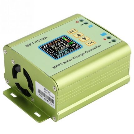
There are quite a few controllers for low currents (10-20A) on the market, but since In our case, a lithium battery is used instead of a lead one, then you need to choose a controller with adjustable (adjustable) parameters. A controller was bought, as in the photo, the price of the issue from $ 13 on eBay to $ 20-30, depending on the greed of local sellers. The controller is proudly called "Intelligent PWM Solar Panel Charge Controller", although in fact all its "intelligence" consists in the ability to set charge and discharge thresholds, and structurally it does not differ much from a conventional DC-DC converter.
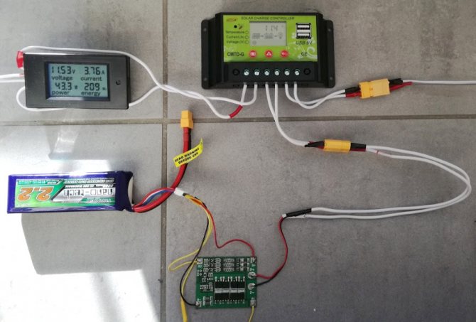
Connecting the controller is quite simple, it has only 3 connectors - for the solar panel, load and battery, respectively. In my case, a 12V LED strip was connected as a load, the battery is still the same test battery with Hobbyking. Also on the controller there are 2 USB connectors, from which you can charge various devices.
All together it looked like this:
Before using the controller, you need to configure it. Controllers of this model are sold in different modifications for different types of batteries, the differences are most likely only in the preset parameters. For my three cell lithium battery (3S1P) I have set the following values:
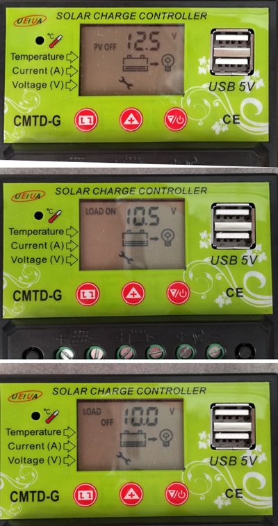
As you can see, the charge cut-off voltage (PV OFF) is set to 12.5V (based on 4.2V, 12.6 could be put per cell, but a slight undercharge has a positive effect on the number of battery cycles). The next 2 parameters are disconnecting the load, in my case it is set to 10V, and re-enabling the charge at 10.5V. The minimum value could be set even less, up to 9.6V, a small margin was left for the operation of the controller itself, which is powered by the same battery.
Types
On / Off
This type of device is considered the simplest and cheapest. Its only and main task is to turn off the supply of charge to the battery when the maximum voltage is reached to prevent overheating.
However, this type has a certain disadvantage, which is too early shutdown. After reaching the maximum current, it is necessary to maintain the charging process for a couple more hours, and this controller will immediately turn it off.
As a result, the battery charge will be in the region of 70% of the maximum. This negatively affects the battery.
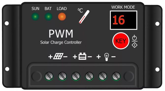
PWM
This type is an advanced On / Off. The upgrade is that it has a built-in pulse width modulation (PWM) system. This function allowed the controller, upon reaching the maximum voltage, not to turn off the current supply, but to reduce its strength.
Because of this, it became possible to charge the device almost one hundred percent.
MRRT
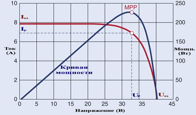
This type is considered the most advanced at the present time. The essence of his work is based on the fact that he is able to determine the exact value of the maximum voltage for a given battery. It continuously monitors the current and voltage in the system. Due to the constant receipt of these parameters, the processor is able to maintain the most optimal values of current and voltage, which allows you to create maximum power.
If we compare the controller MPPT and PWN, then the efficiency of the former is higher by about 20-35%.
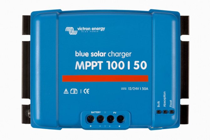
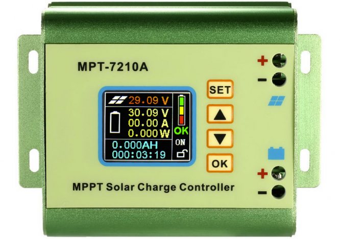
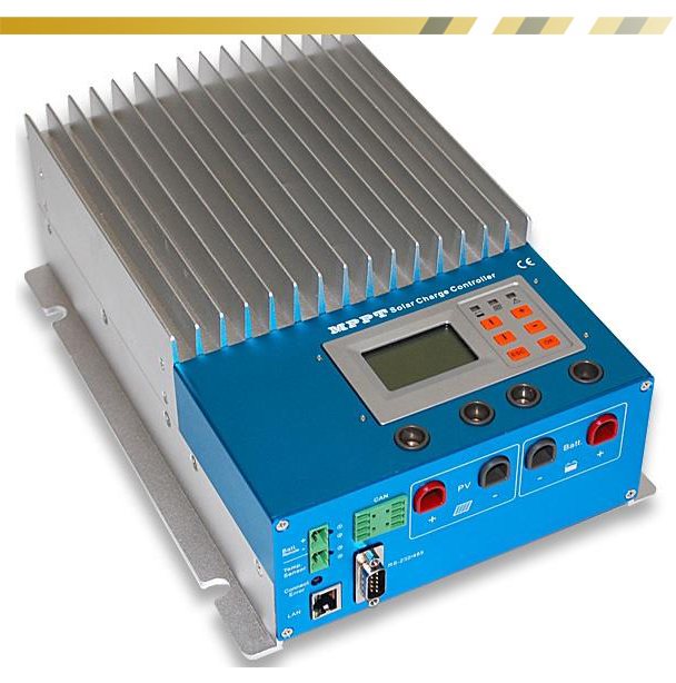
MRRT devices
The most efficient and stable controllers are considered to be solar battery controllers of the MPRT modification - Maximum Power Point Tracking. These devices monitor the charging power when the maximum limit is reached. This process uses sophisticated algorithms to control voltage and current readings, establishing the most optimal ratio of characteristics that ensure maximum efficiency of the solar system.
In the process of operation, it has been practically established that the mppt solar controller is more advanced and significantly differs from other models. Compared to PWM devices, it is about 35% more efficient, respectively, the system itself turns out to be the same.
The higher quality and reliability of such devices is achieved through a complex circuit, complemented by components that provide close control in accordance with the operating conditions. Special circuits monitor and compare current and voltage levels, and then determine the maximum output power.
The main feature of MPPT controllers is the ability to adjust the solar panel to maximum power, regardless of the weather at the moment. Thus, the battery works more efficiently and provides the necessary battery charge.
Selection options
There are only two selection criteria:
- The first and very important point is the incoming voltage. The maximum of this indicator should be higher by about 20% of the open circuit voltage of the solar battery.
- The second criterion is the rated current.If the PWN type is selected, then its rated current must be higher than the short-circuit current of the battery by about 10%. If MPPT is chosen, then its main characteristic is power. This parameter must be greater than the voltage of the entire system multiplied by the rated current of the system. For calculations, the voltage is taken with discharged batteries.
Selection according to the power of the array of solar panels

The main parameter of the solar charge controller is the operating voltage and the maximum amperage that the charge controller can work with. It is very important to know such parameters of solar panels as:
- Nominal voltage is the operating voltage of the solar battery circuit, closed to the load, i.e. per controller;
- Open loop voltage is the maximum achievable voltage of the solar circuit, not connected to the load. This voltage is also called open circuit voltage. When connected to a solar controller, the controller must be able to withstand this voltage.
- Maximum solar input current, solar circuit short-circuit current. This parameter is rarely indicated in the characteristics of the controller. To do this, you need to find out the fuse rating in the controller and calculate the magnitude of the short-circuit current of the solar modules in the circuit. For solar panels, the short-circuit current is usually always indicated. The short-circuit current is always higher than the maximum operating current.
- Rated operational current. The current of the connected solar circuit, which is generated by the solar panels under normal operating conditions. This current is usually lower than the specified current in the characteristics for the controller, since the manufacturers, as always, indicate the maximum amperage of the controller.
- Rated power of connected solar panels. This power represents the product of the operating voltage and the operating current of the solar panels. The power of the solar panels connected to the controller must be equal to or less than the indicated one, but not more. If the power is exceeded, the controller may burn out in the absence of fuses. Although most controllers naturally have fuses rated for 10-20% overload for 5-10 minutes.
Ways to connect controllers
Considering the topic of connections, it should be noted right away: for the installation of each individual device, a characteristic feature is the work with a specific series of solar panels.
So, for example, if a controller is used that is designed for a maximum input voltage of 100 volts, a series of solar panels should output a voltage no more than this value.
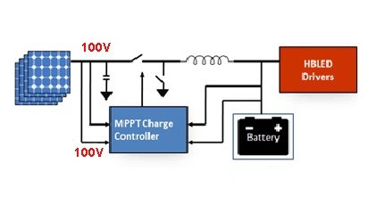
Any solar power plant operates according to the rule of balance between the output and input voltages of the first stage. The upper voltage limit of the controller must match the upper voltage limit of the panel
Before connecting the device, you need to decide on the place of its physical installation. According to the rules, the place of installation should be selected in dry, well-ventilated areas. The presence of flammable materials near the device is excluded.
The presence of sources of vibration, heat and humidity in the immediate vicinity of the device is unacceptable. The installation site must be protected from atmospheric precipitation and direct sunlight.
PWM Model Connection Technique
Almost all manufacturers of PWM controllers require an exact sequence of connecting devices.
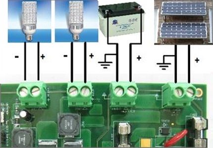
The technique of connecting PWM controllers with peripheral devices is not particularly difficult. Each board is equipped with labeled terminals. Here you simply need to follow the sequence of actions.
Peripheral devices must be connected in full accordance with the designations of the contact terminals:
- Connect the battery wires to the battery terminals of the device in accordance with the indicated polarity.
- Switch on the protective fuse directly at the point of contact of the positive wire.
- On the contacts of the controller intended for the solar panel, fix the conductors coming out from the solar panels of the panels. Observe polarity.
- Connect a test lamp of the appropriate voltage (usually 12 / 24V) to the load terminals of the device.
The specified sequence must not be violated. For example, it is strictly forbidden to connect solar panels in the first place when the battery is not connected. By such actions, the user runs the risk of "burning" the device. This material describes in more detail the assembly diagram of solar cells with a battery.
Also, for PWM series controllers, it is unacceptable to connect a voltage inverter to the load terminals of the controller. The inverter should be connected directly to the battery terminals.
Procedure for connecting MPPT devices
The general requirements for physical installation for this type of apparatus do not differ from previous systems. But the technological setup is often somewhat different, since MPPT controllers are often considered more powerful devices.
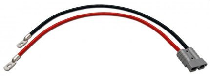
For controllers designed for high power levels, it is recommended to use cables of large cross-sections, equipped with metal terminators, at the power circuit connections.
For example, for high-power systems, these requirements are complemented by the fact that manufacturers recommend taking a cable for power connection lines designed for a current density of at least 4 A / mm2. That is, for example, for a controller with a current of 60 A, a cable is needed to connect to a battery with a cross section of at least 20 mm2.
The connecting cables must be equipped with copper lugs, tightly crimped with a special tool. The negative terminals of the solar panel and battery must be equipped with fuse and switch adapters.
This approach eliminates energy losses and ensures the safe operation of the installation.
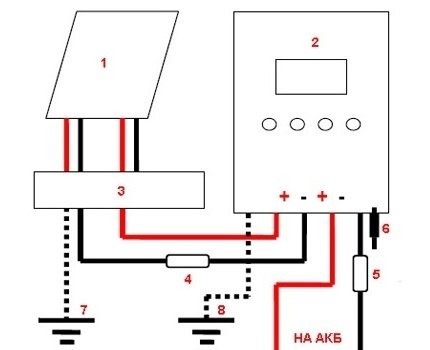
Block diagram for connecting a powerful MPPT controller: 1 - solar panel; 2 - MPPT controller; 3 - terminal block; 4.5 - fuses; 6 - controller power switch; 7.8 - ground bus
Before connecting solar panels to the device, make sure that the voltage at the terminals matches or is less than the voltage that is allowed to be applied to the controller input.
Connecting peripherals to the MTTP device:
- Place the panel and battery switches in the off position.
- Remove the panel and battery protection fuses.
- Connect the cable from the battery terminals to the controller terminals for the battery.
- Connect the solar panel leads with the controller terminals marked with the appropriate sign.
- Connect a cable between the ground terminal and the ground bus.
- Install the temperature sensor on the controller according to the instructions.
After these steps, you must insert the previously removed battery fuse into place and turn the switch to the "on" position. The battery detection signal will appear on the controller screen.
Then, after a short pause (1-2 minutes), replace the previously removed solar panel fuse and turn the panel switch to the “on” position.
The instrument screen will show the voltage value of the solar panel. This moment testifies to the successful launch of the solar power plant into operation.
Selection of a controller for voltage and current of solar panels and battery
Most of the solar panels produced have a nominal voltage of 12 or 24 volts. This is done in order to be able to charge the batteries without additional voltage conversion. Rechargeable batteries appeared much earlier than solar panels and have a common nominal voltage standard of 12 or 24 volts. Accordingly, most solar controllers are available with a nominal operating voltage of 12 or 24 volts, as well as dual-range 12 and 24 volts with automatic voltage sensing and switching.
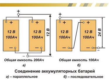
The nominal voltages at 12 and 24 volts are low enough for high-power systems. To obtain the required power, it is necessary to increase the number of solar panels and accumulators, connecting them in parallel circuits and significantly increasing the current strength. An increase in current strength leads to heating of the cable and electrical losses. It is necessary to increase the thickness of the cable, the consumption of metal increases. Powerful high-current controllers are also needed, and such controllers are very expensive.
To eliminate the increase in current, controllers for high-power systems are made for nominal operating voltages of 36, 48 and 60 volts. It is worth noting that the voltage of the controllers is a multiple of the voltage of 12 volts, in order to be able to connect solar panels and battery to serial assemblies. Multiple voltage controllers are available for PWM charging technology only.
As you can see, PWM controllers are selected with a voltage multiple of 12 volts, and in them the nominal input voltage from solar panels and the nominal circuit voltage of the connected batteries must be the same, i.e. 12V from SB - 12V to battery, 24V at 24, 48V at 48V.
For MPPT controllers, the input voltage can be equal or arbitrarily higher several times without a multiple of 12 Volts. Typically MPPT controllers have solar input voltages of 50 Volts for simple models and up to 250 Volts for high-power controllers. But it should be borne in mind that, again, manufacturers indicate the maximum input voltage, and when connecting solar panels in series, their maximum voltage, or no-load voltage, should be added. Simply put: the input maximum voltage is any from 50 to 250V, depending on the model, the nominal or minimum input will be 12, 24, 36 or 48V. At the same time, the output voltage for charging the battery for MPPT controllers is standard, often with automatic detection and support of voltages at 12, 24, 36 and 48 Volts, sometimes 60 or 96 volts.
There are serial industrial very powerful MPPT controllers with input voltage from solar panels at 600V, 800V and even 2000V. These controllers can also be freely purchased from Russian equipment suppliers.
Besides choosing a controller by operating voltage, controllers should be selected according to the maximum input current from solar panels and the maximum charging current of the battery.
For a PWM controller, the maximum input current from the solar panels will go into the battery charging current, i.e. the controller will not charge with more current than the solar panels connected to it give out.
In the MPPT controller, everything is different, the input current from the solar panels and the output current for charging the battery are different parameters. These currents can be equal if the nominal voltage of the connected solar panels is equal to the nominal voltage of the connected battery, but then the essence of the MPPT conversion is lost, and the controller's efficiency decreases. In MPPT controllers, the rated input voltage from solar panels should be 2-3 times higher than the rated voltage of the connected batteries. If the input voltage is lower than 2 times higher, for example, 1.5 times, then there will be less efficiency, and more than 3 times higher, then there will be large losses for the difference in voltage conversion.
Accordingly, the input current will always be equal to or lower than the maximum output current of the battery charge. Hence it follows that MPPT controllers must be selected according to the maximum charging current of the battery. But in order not to exceed this current, the maximum power of the connected solar panels is indicated, at the nominal voltage of the circuit of the connected batteries. Example for a 60 Amp MPPT charge controller:
- 800W at power plant battery voltage 12V;
- 1600W at a power plant battery voltage of 24V;
- 2400W at 36V power plant battery voltage;
- 3200W at a power plant battery voltage of 48V.
It should be noted that this power at 12 volts is indicated for the charging voltage from solar panels of 13 - 14 volts, and is a multiple for other systems with voltages of 24, 36 and 48 volts.
Homemade controller: features, accessories
The device is designed to work with only one solar panel, which generates a current with a strength not exceeding 4 A. The battery capacity, which is charged by the controller, is 3,000 A * h.
To manufacture the controller, you need to prepare the following elements:
- 2 microcircuits: LM385-2.5 and TLC271 (is an operational amplifier);
- 3 capacitors: C1 and C2 are low-power, have 100n; C3 has a capacity of 1000u, rated for 16 V;
- 1 indicator LED (D1);
- 1 Schottky diode;
- 1 diode SB540. Instead, you can use any diode, the main thing is that it can withstand the maximum current of the solar battery;
- 3 transistors: BUZ11 (Q1), BC548 (Q2), BC556 (Q3);
- 10 resistors (R1 - 1k5, R2 - 100, R3 - 68k, R4 and R5 - 10k, R6 - 220k, R7 - 100k, R8 - 92k, R9 - 10k, R10 - 92k). They can all be 5%. If you want more accuracy, then you can take 1% resistors.
How can I replace some components
Any of these elements can be replaced. When installing other circuits, you need to think about changing the capacitance of the capacitor C2 and selecting the bias of the transistor Q3.
Instead of a MOSFET transistor, you can install any other. The element must have a low open channel resistance. It is better not to replace the Schottky diode. You can install a regular diode, but it needs to be placed correctly.
Resistors R8, R10 are 92 kOhm. This value is non-standard. Because of this, such resistors are difficult to find. Their full replacement can be two resistors with 82 and 10 kOhm. They need to be included sequentially.
If the controller will not be used in a hostile environment, you can install a trimmer resistor. It makes it possible to control voltage. It will not work for a long time in an aggressive environment.
If it is necessary to use a controller for stronger panels, it is necessary to replace the MOSFET transistor and diode with more powerful analogs. All other components do not need to be changed. It makes no sense to install a heatsink to regulate 4 A. By installing the MOSFET on a suitable heatsink, the device will be able to operate with a more efficient panel.
Main types
- PWM (PWM) charge controllers... Allows you to achieve 100% battery charging. But due to the lack of a mechanism for converting surplus voltage into amperage and technology for tracking the maximum point, this type of controller is not able to squeeze out all that they are capable of from solar panels. Devices of this type are usually used in small systems up to 2 kW.
- MRPT charge controllers... The most advanced and difficult to date. They are efficient and reliable in operation, have a wide range of settings and various security elements. The use of controllers of this type allows you to accelerate the payback of solar power plants. Due to the mechanism for converting voltage into current and an intelligent tracking system for the maximum point, their efficiency is 20-30% higher compared to previous models. This type of device is used both in small and large (industrial) facilities. And also in places with a limited area for placing solar panels in a situation where you need to get the most out of them (for example, on cars, boats or yachts)
Principle of operation
In the absence of current from the solar battery, the controller is in sleep mode. It does not use any of the battery wool. After the sun's rays hit the panel, electric current begins to flow to the controller. It should turn on. However, the indicator LED along with 2 weak transistors only turns on when the voltage reaches 10 V.
After reaching this voltage, the current will flow through the Schottky diode to the battery.If the voltage rises to 14 V, amplifier U1 will start operating, which will turn on the MOSFET. As a result, the LED will go out, and two low-power transistors will be closed. The battery will not charge. At this time, C2 will be discharged. On average, this takes 3 seconds. After the discharge of the capacitor C2, the hysteresis of U1 will be overcome, the MOSFET will close, the battery will start charging. Charging will continue until the voltage rises to the switching level.
Charging occurs periodically. Moreover, its duration depends on what the charging current of the battery is, and how powerful the devices connected to it are. Charging continues until the voltage reaches 14 V.
The circuit turns on in a very short time. Its inclusion is influenced by the time of charging C2 with a current that limits the transistor Q3. The current cannot be more than 40 mA.