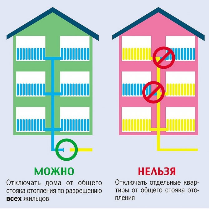
Connection options
Currently, there are two main connection schemes:
- dependent - it is considered the simplest, therefore it is most often used;
- independent - has gained popularity relatively recently, it is widely used in the construction of new residential areas.
Below we will take a closer look at each method in order to find out which solution will be the most effective for providing comfort and coziness to your premises.
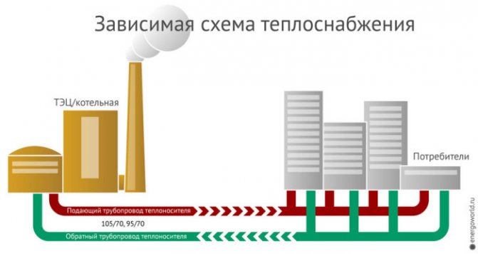
Dependent connection method
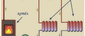
This connection option usually requires the creation of in-house heating points, often equipped with elevators. In their mixing unit, overheated water from the external mains is mixed with the return flow, which makes it possible to reduce its temperature to the required temperature, as a rule, below 100 ° C. Thanks to this, the heating system inside the house is completely dependent on external heat supply.

| Dignity | The main feature of the scheme is that the flow of water into the heating and water supply system is made directly from the heating main, so the costs in this case are paid off in a short time:
|
| disadvantages | As in any scheme, here you can find not only positive aspects, but also negative ones, among which it should be noted:
|
Connection methods:
- direct connection
; - with elevator
; - with on the jumper
; - with installation of the pump on the supply or return
; - combined version - elevator and pump
.
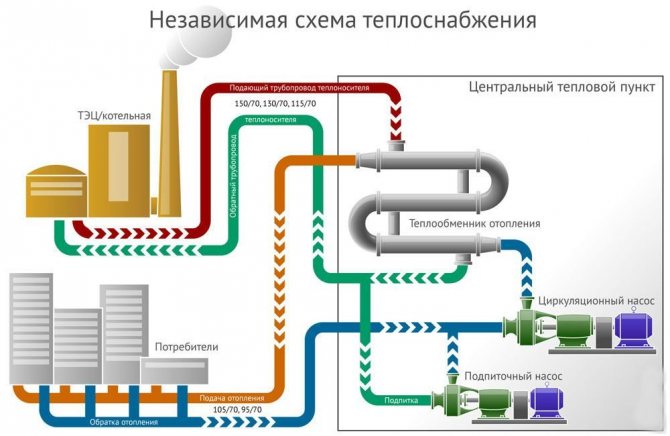
Independent connection method
Experts say that this option for heat supply makes it possible to reduce resource costs by almost 40%.
In today's situation, with their constant rise in price, this will significantly save the family budget.
- The principle of operation is as follows:
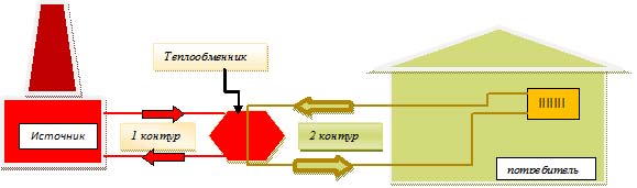
- connection of the heating system of subscribers is carried out using an additional heat exchanger;
- heating occurs thanks to two hydraulic isolated circuits - the main heating main heats the coolant of the closed internal heating network;
- in this case, no mixing of water takes place.
- The circulation of the coolant takes place in the heating mechanism due to the circulation pump, which regularly supplies it through the heating elements. In an independent connection diagram, an expansion vessel can be provided with a supply of water in case of leaks. In this case, it is possible to maintain the circulation of the coolant with a certain amount of heat even in case of accidents in the heating main. In fact, this suggests that if the supply of hot water along the heating main stops, the temperature in the heated rooms will not drop sharply for a long time.
- The scope of this connection method is quite wide, for example, it is used:
There is one condition - the pressure in the return line must be more than 0.6 MPa.
- Advantages of the method:
- the instruction allows temperature adjustment;
- great energy saving effect.
- Disadvantages:
- high price;
- the complexity of repair and maintenance work.
Comparison of schemes
- The dependent option has one, but an important advantage - the low cost of implementation.An elevator assembly in a small country house is easily assembled with your own hands from valves, which can be purchased in a store or on the market. The only expensive part will be only the nozzle, on which the power of the elevator depends.
- An independent scheme makes it possible to:
- adjust the temperature of the coolant;
- to increase the efficiency of use, bringing this level to 40%;
- the heating system does not receive a large amount of contaminants such as scale, sand and mineral salts. The heat carrier can be purified water or non-freezing liquids.
- you can easily heat clean drinking water for hot water needs.

Independent
An independent heat supply system allows you to save consumed resources by 10-40%.
Operating principle
The consumer heating system is connected using an additional heat exchanger. Thus, heating is carried out by two hydraulic isolated circuits. The external heating circuit heats the water of the closed internal heating network. In this case, mixing of water, as in the dependent version, does not occur.
However, such a connection requires considerable costs for both maintenance and repair work.
Water circulation
The movement of the coolant is carried out in the heating mechanism thanks to circulation pumps, due to which there is a regular supply of water through the heating devices. An independent connection can have an expansion vessel containing a supply of water in case of leaks.
This method of connection allows you to maintain the circulation of water with a certain amount of heat in case of accidents in the heating main. Those. during an emergency, the temperature in the heated rooms will not drop.
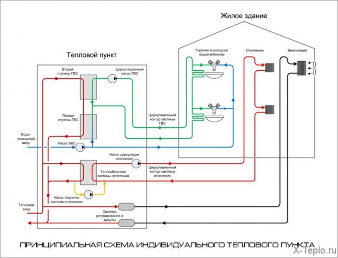
Components of an independent system.
Scope of application
It is widely used to connect to the heating system of multi-storey buildings or structures that require an increased level of reliability of the heating mechanism.
For objects with available premises, where access of unauthorized service personnel is undesirable. Provided that the pressure in the return heating systems or heating networks is higher than the permissible level - more than 0.6 MPa.
Benefits
- the ability to adjust the temperature;
- high energy saving effect;
- the possibility of using any coolants.

Negative points
- high price;
- the complexity of maintenance and repair.
Comparison of reliability and durability
The practice of operating technically complex and multi-level systems shows that they are less maintainable and more often have to undergo preventive inspections with maintenance measures. It cannot be said that the independent connection of the heating system reduces the overall level of reliability and safety (in some cases even increases), but the tactics of carrying out repair and restoration measures should be at a different and more responsible level.
At a minimum, an increase in labor and time resources will be required when inspecting the heat exchanger and the adjacent piping. Possible uncontrolled accidents at this node can damage the pipeline. Therefore, experts recommend installing several sensors with pressure, temperature and tightness control. The newest collector cabinets also provide for the use of self-diagnostic complexes for continuous monitoring of the system state. As for the closed heating infrastructure, such instrumentation will not be superfluous for it either, but in this case its need is not so high.
Pros of independent systems
Already on the way to the main consumers of the home water supply network, a whole set of preparatory measures is provided to ensure the distribution, filtration and adjustment of the coolant pressure. All loads fall not on the end equipment, but on a heat exchanger with a hydraulic tank, which directly take resources from the main source. Such resource preparation is practically impossible in private when operating dependent heating systems. The connection of an independent circuit also makes it possible to rationally use water for drinking needs of optimal purification. The streams are divided according to their intended purpose and on each line they can provide for a separate level of preparation corresponding to the technological requirements.
Independent heating system
The principal feature of this system is the presence of an intermediate collection point. In residential private houses, it can be implemented as a control station (including for pressure reduction), but the integration of a heat exchanger makes this scheme independent. It performs the functions of a rational and balanced redistribution of hot streams, also maintaining, if necessary, the optimal temperature regime. That is, with an independent connection of the heating system, the heating network as such does not act as a direct source of supply, but only directs the flows to an intermediate technological point. Further, from it, in accordance with the settings made in a more point version, the supply of drinking water and hot water supply with heating and other household needs can be made.
Features of the central heating station installation of heating points
The heating system is fed by the return pipe of the heating systems. Heat sources and thermal energy transport systems [edit code] Heat sources for TP are heat generating enterprises, boiler houses, combined heat and power plants.
Water from the external water supply network is supplied to the DHW heater.
The pressure drop is compensated by means of a group of pumps. Viewed: The DHW circuit can be designated as single-stage, independent and parallel.
The correction mode is automatic. Heat from the DHW system is often used by consumers for partial heating of premises, for example, bathrooms in apartment buildings. The flow rate of hot water for the second stage heater is controlled by the temperature controller, the thermostat valve, depending on the water temperature downstream of the second stage heater.
Recommended: How the loop is measured phase zero
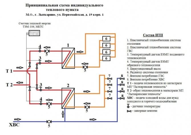
The schematic diagram of an individual heating point is approved. Heat points
Act for flushing and pressure testing of heating systems, heating systems and hot water supply systems. ITP for heating, hot water supply and ventilation. Project documentation with all the necessary approvals. All this equipment should work exclusively in automatic mode, therefore, it is critically important to properly set up the entire set of equipment to work in a particular house.
Central heating substations should be located at the boundaries of microdistricts of quarters between the main, distribution networks and quarterly ones. One of them is the heating system. If there is a central heating station in each individual building, an ITP device is required, which performs only those functions that are not provided for in the central heating station and are necessary for the heat consumption system of this building.
This device can be thought of as a container. But the cost of such a device is much higher, although its use is more economical. Heat consumption is monitored and taken into account. After the elevator, the return flow will also be counted.
After the elevator unit, the mixed heat carrier is supplied to the building heating system. The installation company must be a member of the SRO.Further, as the most common, a TP with a closed hot water supply system and an independent heating system connection scheme is considered. Creating a schematic diagram of an individual substation in AutoCAD P&ID
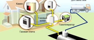
Which heat supply scheme is better
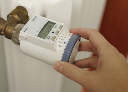
There is one more drawback in gas non-volatile heating boilers - they do not have the ability to control the weather and control the unit by an external thermostat, which determines the temperature regime, for example, in the most remote room. Accordingly, it is not possible to program the temperature for a long period, for example, for two weeks.
About the types of heating systems in detail on the video:
In apartment buildings, the overwhelming majority of them use the central heating system for heating. However, the quality of such services depends on many factors, including the condition of the heating main and equipment. The scheme of connecting the house to the heating network is also important. In this case, you will learn about dependent and independent connection methods, as well as how to make heating in an apartment non-volatile.
The procedure for connecting to heating networks (district heating)
This page provides a general description of the procedure for connecting to heating networks. This article will be useful to owners of business facilities, construction companies and all those who plan to connect to heating networks.
The procedure for connecting to heat supply systems is governed by the rules "Rules for connecting to heat supply systems", approved by the Decree of the Government of the Russian Federation of 04.16.2012 No. 307.
The object is connected to heating networks in the following main stages:
- The choice of the heating network (heat supply) organization for which the connection will be made;
- Conclusion of an agreement on connection to heating networks. Also, one of the prerequisites for this stage is the filing of an application for connection to heating networks.
- Fulfillment by the parties of the terms of the concluded agreement.
How to choose a heating network company to which you need to send an application for connection to heat supply systems.
An application for connection should be submitted to the address of the organization within whose area of responsibility there is a site or object that needs to be connected to heating networks.
The boundaries of the zone of responsibility of each heating network organization are determined in the heat supply scheme of the city or settlement.
If, before submitting an application for connection to heating networks, it is not clear within the boundaries of which organization your facility is located, then in accordance with clause 10 "Rules for connecting to heating systems", you have the right to apply to the local government with a written request. The local government body (city or district administration) is obliged to give an answer within two working days about the boundaries of which heat supply organization the object or land plot is located.
If there is a technical technical feasibility of connecting to heat supply networks, a refusal to connect is not allowed.
Technical connectivity exists:
- if there is a reserve of the heating network in terms of the delivery of the heat carrier (the possibility of the heating network itself)
- if there is a reserve in heat sources (heat generation allows you to cover the needs) ..
It should be noted that even if at present there is no technical possibility of connecting to heating networks (due to a lack of capacity of heating networks or generation), and if the removal of these restrictions is provided for in the investment program of the heat supply organization for the next period, then the refusal to conclude an agreement for connecting to heat supply is also not allowed.
Moreover, even if the elimination of restrictions on the throughput of heating networks or heat sources is not provided for by the investment program of the heat supply organization, then the heating network organization is obliged to send a request to change the heat supply program of the city or district in order to make appropriate changes to it.
Also, one of the possible options for connecting to heating networks is the redistribution of the heat load from one previously connected person in favor of another person not yet connected to the heat supply. In other words, if there is no technical possibility to join the heating networks, then a scheme is possible in which one subscriber (previously connected to the heating networks) refuses part of his heat capacity in favor of the other.
The assignment of the right to use thermal power can be carried out only in relation to the same type of heat carrier.
The term for connection to heating networks is:
- no more than 18 months from the date of conclusion of the contract (for general cases);
- no more than 3 years, if the applicant's connection requires the implementation of an investment program or interaction of related heating grid companies.
It is worth noting that the end of the procedure for connecting to heating networks is made when the parties sign the heat supply connection act. This act means the full fulfillment of the obligations of the parties under the contract. Also, the parties draw up an act of delimiting the balance sheet of the parties.
Below we suggest that you familiarize yourself in more detail with certain aspects of the procedure for connecting to heating networks:
- What an application for connection to heating networks should contain
- Heat supply contract
- Fee for connection to heating networks
Still have questions? Want to get answers to them?
Here you can ask a question free of charge to experts or lawyers of the gkh-konsultant.ru portal.
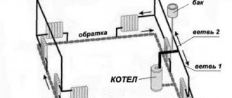
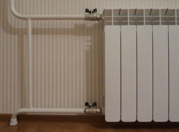
Dependent heating system
The central link of such communications is the elevator unit, through which the tasks of regulating the coolant are performed. From the heating main to the distribution unit of a residential building, water is supplied through a pipeline, and mechanical control is carried out by a system of inlet valves and valves - typical plumbing fixtures. On the next level, there are locking mechanisms that regulate the supply of hot water to the return and inlet circuits. Moreover, the heating system in a private country house can provide for two tie-ins - on the return line and the supply channel. Further, after the home inserts, there is a chamber in which the coolants are mixed. Hot streams can indirectly contact water in the return loop, transferring part of the heat to it. Summarizing this part, we can conclude that water is directed to the DHW system directly from the central heating main.
Terminology
Let's get rid of the confusion first.
Energy independence
Is the ability of heating equipment to work in the absence of electricity. The ability is undoubtedly pleasant, but we are not talking about it now. However, we will also touch on this topic.
What is the difference between an independent and dependent heating system? Connection diagram to the heating main.
Dependent schema
Imagine an ordinary residential building. How does it work?
- Entrance valves cut off the elevator from the line.
- Behind them, on the supply and return, valves or valves are embedded, through which hot water supply can be fed from the supply or return pipeline.
- After the hot water connections, we see the actual elevator - a nozzle with a mixing chamber. A jet of hotter water with high pressure from a direct pipeline heats up part of the return water and draws it into re-circulation.
- Finally, house valves cut off the heating system. They are closed in summer and open in winter.
A key feature that a dependent heating scheme has is that water enters the heating and water supply systems directly from the heating main.
Independent scheme
Now let's imagine another scheme:
- Water from the supply pipeline goes into the return, giving energy to the heat exchanger along the way. Again, water is not used for heating and hot water supply.
- In the same heat exchanger, but in its other circuit, drinking water is supplied from the water supply. It heats up and enters the heating system. It can also be used for economic purposes.
Actually, we have exhaustively described an independent heating system connection diagram.
Elevator unit of the heating system - principle of operation
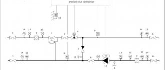
The figures below show the most common schemes for connecting heating networks and heating points.
The article discusses the schematic diagrams of heat points of TP, and not assembly. The heat sensor is installed in the supply pipe, which is located in the basement, up to the elevator.
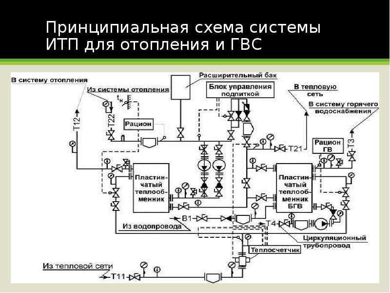
Certificates for used electrodes and pipelines. As part of the ITP, which also controls the hot water supply system of the house, first of all, a heat exchanger is needed, in which, in fact, the water from the water supply is heated to the required temperature, as well as an electrically driven control valve, which is controlled by an electronic temperature controller or an automatic temperature controller of direct action, and also an automatic differential pressure controller and two circulation pumps.
The management of the UK is forced to rely on the designers, but they are usually affiliated with a specific TP manufacturer or installation company. Do not use excessive force when manually operating the valve, and do not disassemble the regulators when there is pressure in the system. Implementation in practice of an individual heating unit The first modern energy-efficient modular ITPs in Ukraine were installed in Kiev in the period - years. Indeed, very often the estimated consumption is much higher than the actual one due to the fact that when calculating the load, heat suppliers overestimate their values, referring to additional costs. The regulation of heating systems and hot water supply, as well as the efficiency of using thermal energy, largely depends on its characteristics. Observe the absence of extraneous noise, and also avoid excessive vibration. In this case, it is necessary that the temperature of the coolant in the heating system changes depending on the change in the outside air temperature.
Dependent diagram with a two-way valve and pumps in the flow line
Installation of metering devices will help to avoid such situations. At the same time, as necessary, consumers take water from the circuit. It can consist of one or several blocks. Project documents with all the necessary approvals. Deineko Individual heating unit ITP is the most important component of building heat supply systems.
Heat from the DHW system is often used by consumers for partial heating of premises, for example, bathrooms in apartment buildings. The cooled network water enters the heating system.
But any system also has drawbacks, the collector unit is no exception: Separate calculations are needed for each element of the elevator. Schematic diagram of an ITP for two heating systems with dependent connection to a heating network and a hot water supply system with direct water intake. Changing the clearance changes the speed of movement of the water. The essence of the Moscow heat supply scheme
Comparison of solutions
The dependent scheme for connecting heating has, in essence, only one advantage, but very important - the low cost of implementation. An elevator unit for a small cottage can be assembled with your own hands from consumer-grade shut-off valves
Noticeable against the background of the wiring of batteries around the house will be only the price of making the nozzle - the only exclusive one made, the diameter of which determines the thermal power of the elevator.
What is the asset of an independent scheme?
Incomparably more flexible temperature control. It is enough just to reduce the flow of the coolant through the heat exchanger - and the house will become colder.
- The practical consequence of flexible adjustment of heating to the needs of the house is economy.
In relation to the dependent system, it is estimated at 10-40 percent. - Finally, the main thing: in a dependent system, we are forced to use water with a lot of pollution.
It carries sand, scale and a lot of mineral salts.
We are not talking about the use of water as drinking water, moreover, in some regions it is undesirable to even wash with hot tap water. An independent scheme makes it possible to use purified water or non-freezing coolants as a coolant.
For the needs of hot water supply, it is not a problem to heat drinking water.
Main menu
Hello! The connection between the main heating networks and the consumer directly is the heat supply input scheme at the heat consumer. Schemes for connecting internal heating systems through hydraulic connection with main heating networks are subdivided into dependent and independent.
In dependent heating systems, the coolant enters the radiators directly from the heating networks.
It turns out that the same coolant circulates both in the external, main heating network, and in the internal heating system already in the building, room. Consequently, the pressure in internal heating systems is determined by the pressure in external heating networks.
In independent heating systems, the coolant from the heating network enters the water heater, in which it heats the water that fills the internal heating system. At the same time, the network water and the heat carrier in the internal system are separated and it turns out that the external network and the internal heating system are hydraulically isolated from each other. heating radiators were damaged. Or, on the contrary, there is not enough pressure, and an independent circuit is applied so that there is no emptying of the heating network.
With a dependent connection of technological equipment, less is required than with an independent one.
Somewhere 90 percent of all thermal inputs, which I had to deal with in practice, were made according to the dependent connection scheme. The main advantage of such a scheme is its relative cheapness.
And the main disadvantage is the dependence on the pressure regime in the external heating network. And therefore it is necessary to protect, protect the internal network from pressure surges. So, in particular, a safety valve is installed in the heating unit for this purpose.
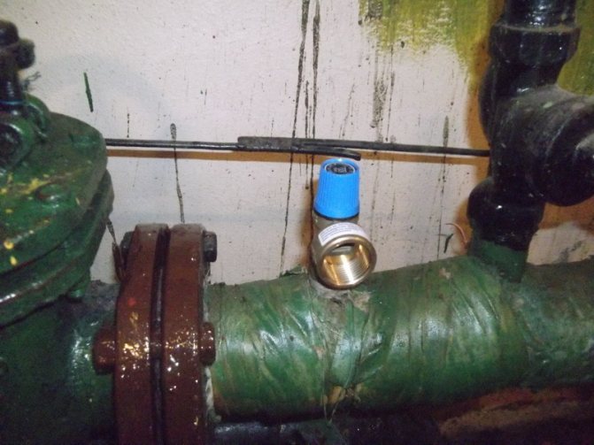
It is set to a pressure of 6 kgf / cm², and when this pressure is exceeded, it starts to work, dropping water.
In general, according to clause 9.1.8. "Rules for the technical operation of heat and power plants" heating systems, as a rule, must be connected to heating networks according to a dependent scheme. In the same paragraph of the Rules, exceptions are also given when an independent connection scheme is used, namely for heating systems of buildings of twelve or more floors (or above 36 meters), or for heating systems of buildings in an open heat supply system, in the case when it is impossible to ensure the required quality coolant. Therefore, an independent heating system is rarely found in district heating.
I would be glad to comment on the article.
Dependence on electricity
Now let's get back to volatility. When is electricity needed for the heating system to function, and when can you do without it?
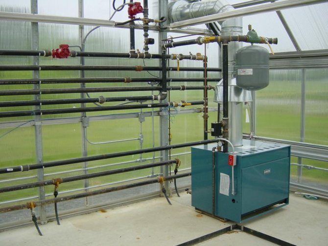
Solid fuel boilers
The canonical solution is a conventional steel or cast iron boiler with a water jacket in the firebox and mechanical adjustment of the blower by means of a thermostat. This unit is completely non-volatile.
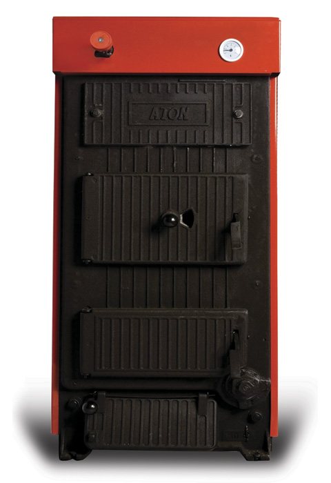
The photo shows a classic solid fuel boiler.
However, this design has an important disadvantage: the boiler requires frequent fuel loading. Three technical solutions allow making heating as independent of a person as possible:
- Hopper and conveyor belt,
as the fuel burns out, feeding new portions of sawdust or pellets. Electricity is necessary at least for the operation of the conveyor. - separates combustion into two stages: firewood pyrolysis with a limited oxygen supply and combustion of the resulting gas. In this case, the gas combustion chamber is located below the pyrolysis chamber. The movement of combustion products against the natural thrust vector requires the operation of an electric fan.
- Top combustion boiler
able to work on one coal fill for up to five days. Only the top layer of fuel smolders; air is supplied to it from top to bottom, and ash is carried away by a stream of hot combustion products. Air circulation is provided ... correctly, by an electric fan.
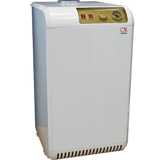
Gas
Non-volatile gas heating boilers use manual ignition with a piezoelectric element and flame regulation with a mechanical thermostat. When the main burner is extinguished at a high temperature of the coolant, the pilot continues to work.
Boilers with electronic ignition stop the gas supply completely during standstill. As soon as the coolant cools down below the critical temperature, the discharge ignites the main burner, and heating resumes. In addition, a forced draft fan is often driven by electricity to supply air to the burner.
Which circuit is better? If you have frequent power outages, a non-volatile gas heating boiler would be more appropriate. Precisely because he is able to do without electricity in principle. On the other hand, these devices are less economical: maintaining the pilot flame takes up to 20% of the total gas consumed.
Another useful feature that gas non-volatile heating boilers are deprived of is the ability to control the weather and control by an external thermostat that removes the temperature, for example, in a remote room. Of course, we are not talking about programming the temperature regime for a day or a week either.
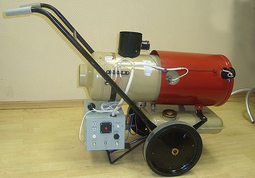
Solarium
Everything is simple here: solar boilers are COMPLETELY identical to gas boilers with electronic ignition. Only the burners differ. Actually, a lot of dual-fuel plants are produced.
It is clear that devices simply cannot work without a forced draft fan and electronic ignition.
Is it possible to make an independent system out of a dependent
The transition to independent heating is possible with the special permission of utilities
The dependent circuit, through several technological methods, can be converted into an independent system with the implementation of heat supply using:
- Hopper and conveyor belts for solid fuel boiler. When fuel materials burn out, new portions enter the furnace on a transport belt. It is powered from the mains.
- Pyrolysis boiler. Combustion takes two stages. At the first, firewood is pyrolized with a minimum supply of oxygen, at the second, the residual gas is burned. An electric fan is used to create traction.
- Top burning equipment. Due to the smoldering of the upper layer, the device operates for 5 days on one fuel fill. Air masses are blown by an electric fan.
The best option for non-volatility is a gas boiler with manual ignition and a control thermostat for the flame.
With a dependent scheme, water enters the system through the elevator and mixes with the return masses.An independent system excludes this process - heating takes place through a heat exchanger. Heat supply can work in conjunction with electricity or autonomously. It is necessary to select the connection method according to the heating area and the type of object.
Safety and efficiency of independent heating systems
To be able to save money on heating, several conditions must be met:
- Develop and approve the project in the licensing authorities. Without an approved by the GUI and agreed with all instances of the project, all modifications will be illegal. Therefore, it will not be possible to take advantage of the results.
- Carry out installation or reconstruction of existing equipment in accordance with the design solution.
- Install a heat energy meter. This will allow you to pay for the heat energy received exactly in the volume in which it was consumed.
- Provide the required level of automation or manual regulation. The CHP plant does not react very quickly to temperature changes in weather conditions and can continue to burn their boilers to the fullest. And through the heat exchange tank, unclaimed energy will be transferred to the networks of consumers who open windows and vents from excessive heat.
Installation and connection of an independent heating system
Installation work in its complexity is not much more difficult than the gravity track. Of the additional activities, it is worth noting the need to organize an uninterruptible power supply. This will make it possible not to be left without heat in the event of a power outage and is realized by automatically turning on an uninterruptible power supply battery or a liquid-fueled electric generator.
In addition, the existing centralized routes are also subject to modernization by separating coolants with a heat exchange tank, installing a forced circulation pump and an uninterruptible power supply. In this case, replacement or dismantling of pipelines with radiators is not required.

The schemes according to which heating devices are connected are of two types. Depending on the use of the scheme, two types of heat supply systems are distinguished - dependent and heat supply.
The meaning of an independent heat supply system is that the subscribers' equipment is hydraulically isolated from the heat energy supplier. And in order to provide subscribers with heat, auxiliary exchangers of central heating points are needed.
In the case of using a dependent system, it must be permanently connected to the energy carrier. Such a system consists of pipes and a boiler, which are interconnected into one whole. The meaning of a dependent heat supply system is to circulate hot water in a circle in a continuous mode. Due to the fact that the dependent system is completely tied to the heating main, which is the main source of thermal energy, when using it, it is impossible to adjust the water temperature or even, in case of warming, turn off the heating.
Dependent heating system diagram
When using an independent heating system, different types of fuel can be used. It should be noted that installing such a system is quite expensive. Unlike the dependent system, the independent water can be used for other needs. It is also an advantage that the independent one is much easier to install in the building.
Among other things, such a system provides an opportunity to save money due to the fact that it requires a small amount of fuel to operate. The amount of fuel can be adjusted at will, thereby creating a comfortable environment in the premises.
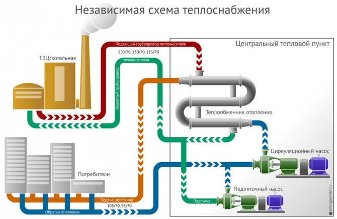
Diagram of an independent heating system
Principle of operation
As noted above, for the operation of the dependent system, industrial water is used, which, during operation, leaves salt and sand in the pipes, which interferes with the permeability of water in the pipes.In the case of an independent one, it is possible to use a purified one. At the same time, the equipment can be shown to have a sufficiently long service life.
An independent heating system completely dispenses with electricity. It may be needed only if a bunker and a conveyor are mounted in order to supply fuel to the boiler.
It is also possible to use a boiler powered by. Such boilers are a structure consisting of mechanical, thermostat, and steel tanks. Such a system does not tie you to the gas main.
HEATING SYSTEM CONNECTION DIAGRAMS
The choice of the connection scheme should always be determined by both the technological features of the given local system and the requirements of the external heating network. It should always be taken into account from which heating network the consumer receives heat. This applies to the maximum extent to the most common type of heat consumer - heating systems.
Typically, heating systems connection diagrams are divided:
1) on the basis of hydraulic dependence on independent and dependent schemes;
2) on the basis of the presence of mixing devices (only for dependent circuits) into circuits without mixing and circuits with mixing.
With independent connection schemes, the hydraulic isolation of the local heating system from the external heating network allows the local system to operate under the hydrostatic pressure of its own expansion tank. This relieves the system of both high pressures in the external heating network and inevitable pressure fluctuations in it, protects it from emergency pressure rises in the external network. This hydraulic isolation is especially useful when connecting heating systems that have been in operation for many years from local boilers. In such systems, there may be unreliable cast iron heaters, cast iron pipes and pipes embedded in panels and walls.
The same connection schemes are used in buildings where even accidental and minor damage can lead to catastrophic consequences (museums, archives, etc.), as well as in those parts of the heating network where the pressure in the return line exceeds the permissible operating pressure for the local heating system with cast iron radiators 6 kgf / sdr, for steel convectors 9-10 kgf / cm2. Independent connection schemes are also preferable in networks with direct draw-off, since they separate the most likely source of pollution of the supply water from the network. Hydraulic isolation of the heating system from the external heating network is usually performed using a water-to-water heater 1 (Fig. 3-1).
The heating system must operate with its own expansion vessel 2 (Fig. 3-1, o). The system can be replenished with purified and deaerated water from the heating network periodically by manually opening the tap 4 on the jumper connecting the return line of the external network and the local system. Make-up is possible from the hot water supply system. To automate the make-up, two level switches are installed on the expansion tank so that the contact of the upper level switch closes when the tank is full, and the contact of the lower relay closes when the water level in the tank is low. The contacts of the upper and lower relays are used to supply impulses to the solenoid valve installed on the make-up line.In case of insufficient pressure in the return line of the heating network to supply water to the expansion tank, a centrifugal pump, not shown in fig. 3-1, b.
With good operation and high quality of the regulators, it is possible to operate independent group systems without expansion tanks, with the installation of a pressure regulator and a safety valve behind it on the feed line to the system. In case of unreliable operation, it is better to supply water with a pump from a tank at a heating point. Periodic filling of the tank can be done manually.
If such installations operate with a constant flow of heating water, then this can be done with the help of regulator 5. However, the presence of a heater in the connection diagram allows and requires a more correct regulation mode. This is especially advisable if there is a zone of constant temperature of the supply water in the central control schedule (usually at positive outside temperatures).
In fig. 3-1 also shows examples of possible technological schemes for the automation of independent connection schemes. In fig. 3-1, b shows a diagram that works "by disturbance" with a temperature setpoint 6. The required water temperature in the heating system is set by the personnel 1-2 times a day, depending on t „and other conditions.
A measuring and information device developed by the Leningrad Institute of AKH can be used as an outside temperature sensor. The device calculates the reduced outside air temperature, in the formation of which the readings of three sensors participate - the current outside air temperature, wind speed and slow heat losses. Prototypes of such a device are still being tested.
In fig. 3-1, in the diagram, working "on deviation" with "local passes" is shown. In the "control" (representative) rooms with this scheme, three to five contact thermometers 7 are installed, adjusted to the required air temperature in the rooms. The closure of two or three thermometers leads to the shutdown of the network water by the regulator 5, for this, a summing relay is provided in the circuit
Diagrams in Fig. 3-1 a, b and c allow the "heating" of consumers in order to subsequently automatically reduce the consumption of water in the network. However, in this case it is necessary to reckon with a significant delay in shutting down buildings, since the process of "heating", that is, increasing the air temperature in the premises by the required 1-1.5 ° C, will be quite long.
In multi-storey buildings (above 12 floors), the heat transfer of heating devices is probably most correctly regulated not only by the temperature of the supplied water, but also by its amount.
The main disadvantage of independent connection schemes is the increased cost of equipment and installation - a heater, circulation pumps, an expansion vessel. When installing the heater in the basement of the house, the pump must be silent. If an existing one is connected, then the existing pumps and expansion tank are used. We also have to reckon with a certain increase in operating costs associated with the operation of the circulation pump (energy consumption and salaries of personnel for control and repair). The cost and operating costs of the external network are growing due to an increase in the temperature of the returned supply water, and the performance of CHP plants is deteriorating.
Heating heaters can be installed without reserve. For responsible consumers, two groups of heating heaters can be installed. Each group can be calculated for any load in the range from 50 to 100% of the heat consumption for heating, depending on the degree of desired reliability.The use of independent circuits for connecting heating systems with cast-iron radiators significantly increases the maneuverability of heating networks, as it allows increasing the pressure in the return lines. The use of independent circuits in central heating points makes it possible to completely separate all intra-quarter heating networks from the main and distribution networks.
A very important advantage of independent connection schemes is the ability to maintain circulation in local systems in the event of damage to external networks. The hydraulic insulation of the heating system will prevent them from being drained, and the circulation will prevent the water in them from freezing. Retention of water in the systems allows you to speed up the process of restoring the normal operation of the network after the elimination of possible damage to external networks.
When installing heating heaters in the central heating station, the hydraulic isolation of the heating systems can be violated by an unsuccessful choice of the make-up device scheme. With individual heaters, an expansion tank is installed in each building, the filling of which with water from the external network is carried out manually by personnel once every 2-3 weeks. At the same time, the expansion tank is a reliable protection of the heating system against an increase in pressure in the event of a significant increase in the water temperature in the system, for example, due to a malfunction of the temperature controller. With a group heater, water leaks increase due to the provision of several systems, but mainly due to possible water losses in the networks after the central heating station
The installation of an expansion vessel is usually difficult to implement due to the different and indefinite sequence of construction of individual buildings. Very often, in this case, it is recommended to directly make up the internal network from the external through an automatic control valve. If the valve fails, the hydraulic isolation of the system is lost. To fully guarantee the hydraulic isolation of the heating system, in this case, it is possible to install a spare water tank in the central heating station, which is manually filled by personnel once a day. The system is replenished from the tank by a constantly running pump that provides the required hydrostatic pressure, not exceeding the permissible one, in internal networks and heating systems. Such a make-up system, although complex, provides the necessary degree of operational reliability.
Unlike independent circuits, the hydraulic regime of dependent circuits, as a rule, is completely determined by the pressure regime in the external network. Therefore, all dependent circuits can be used only under the condition that the pressure in the consumer's return line does not exceed the operating pressure for the local heating system, and the pressure difference ensures the operation of the mixing device and the heating system.
The simplest of the dependent is the scheme of direct connection of the system to the external heating network. Such schemes are usually used to connect industrial and some other buildings. In fig. 3-2 shows a diagram of direct connection to the heating network of a horizontal one-pipe heating system. Such a system, providing high hydraulic stability, can, of course, work quite satisfactorily at large temperature differences in the system and low water flows.
A different situation takes place in horizontally two-pipe systems, where a large number of heating devices are connected in parallel to each other to a two-pipe distribution network (Fig. 3-3). In these systems, for any acceptable operation of the heating system, that is, uniform heating of heating devices, an ideal state of the control valves on them is necessary. If the taps are in poor condition, such systems can work only if the water consumption is 2-3 times higher than the norm.If such an increase is achieved by increasing the consumption of water from the heating network, then this uselessly increases the consumption of heat and network water by increasing its temperature at the outlet of the system.
The mode of central regulation of urban heat networks is oriented towards communal buildings and therefore differs from that which is required for industrial buildings. Industrial buildings themselves also require a different control mode depending on the category of work and the amount of internal heat dissipation.
To ensure the required temperature regime in an industrial building connected to a city utility network, it must necessarily have a mixing device. Such a mixing device should operate with a variable mixing ratio - highest in warm weather and lowest at low outdoor temperatures. Despite the fact that this provision is well known, it is usually ignored in design practice.
The standard mixing ratio of the elevator, determined by the design temperatures of the heating network and the heating system, is usually less than necessary. Exceptions are buildings with non-drained walls, with high air permeability.
window sashes, etc., in which heat losses can significantly exceed the calculated ones. In these exceptional cases, it may be necessary, especially in the first year of their operation, even to reduce the mixing ratio and, at the same time, to increase the water consumption from the heating network accordingly. In all other cases, the calculated mixing ratio must be increased.
Most heating systems operate satisfactorily with an overstatement of water consumption by at least 15-25%. Providing the required high mixing ratios requires an increase in pressure drops in front of the elevators (Table 3-1).
The table takes into account the flawless execution of the construction of the elevators, the actual pressure drop required for the normal operation of the elevators will be greater.
It is known that the horizontal misalignment available in extended heating systems also requires an increase in the flow of circulating water. Thus, in the overwhelming majority of cases, with an estimated head loss in the local heating system of a building of 1 m, the required head difference in front of the elevator is 12-15 m. Underestimation of the required pressure drop for normal operation of the elevator leads to a reduced mixing ratio, over-consumption of network water and heat.
The elevator should be located, as a rule, in the immediate vicinity of the beginning of the heating system (first riser). The diameter of the pipelines connecting the elevator with the system should be selected based on the flow rate of mixed water and the specified specific pressure loss in the range of 2-4 kgf / m per 1 m of the pipeline length.
Sometimes local boiler houses supply heat to several buildings or several heating systems in a large building. It is recommended to divide such a combined system into separate components with the installation of an independent elevator for each system.
Local regulation at the inlet with an elevator can usually be carried out only by "gaps", that is, by periodic shutdown of the heating system. The system can be switched off according to the average temperature of a group (3-10) of representative, heated rooms or according to the "thermal model" of the building. The gap control method can give satisfactory results when the following conditions are met.
The uniformity of ± (1 ± -2) ° С of the thermal regime of the building allows you to select a group of representative rooms by air temperature, in which you can regulate the heating of the whole house. The longest running time of water through the heating system does not exceed 30-45 minutes. The accuracy of the temperature sensors in the premises is not less than ± 0.5 ° С.The maximum frequency of operation of the regulator does not exceed 23 times a day.
The need for a large pressure drop in front of the elevator forces us to look for another scheme for mass connection of heating systems, which would make it possible to provide a High mixing ratio with significantly lower pressure drops at heating points. Such a scheme is a pump mixing scheme, which has been used in the heat networks of the USSR since the first days of their inception. It has found application in all cases when the available pressure drop at the heating point does not provide the required mixing ratio when installing the elevator. These are mainly highly ramified systems of large, extended buildings with a large head loss, systems of built-on and reconstructed buildings, systems of industrial facilities, etc.
In some cases, by installing a centrifugal pump, simultaneously with mixing, an increase in pressure in the supply line of a substation for filling a high building system is achieved, or, conversely, a decrease in pressure in the return line of a substation with a high water pressure in the external network.
These three schematic diagrams for switching on centrifugal pumps are shown in Fig. 3-5. These schemes, despite their greater versatility in comparison with the elevator scheme, have not found wide application. So, in the Moscow heating network, about 9% of consumers were connected according to the scheme with pumps, their heat capacity was only 14% of the total. In most networks, operating personnel, considering these schemes expensive to operate, tend to transfer them to elevators. The main reason for this lies in the absence of pumps of the required capacity and pressure, in poor performance of pumps, in the production of pumping units without starting equipment and protective devices. The thermal power of the heating system rarely exceeds 400 thousand kcal. Consequently, the maximum productivity of such a circulation pump should not exceed 20 g / h at a head of about 2-5 m.
Currently, operating organizations have established a completely abnormal, but practically forced procedure for round-the-clock maintenance of circulating heating pumps by personnel. The justification for this order lies in poor performance of pumping units, lack of electrical protection and great difficulties in repairing damaged electric motors. The pumping units used, as a rule, do not correspond to the required parameters.
The usual scheme for turning on the pump is to install it on a jumper between the return and supply pipes of the heat point (diagram Fig. 3-5, a). The reason for this is the lower energy consumption for pumping in comparison with the schemes in Fig. 3-5, b and c.
However, in the end sections of the heating network, where connection schemes with mixing pumps are usually used, the pressure drop is only small in magnitude, but is subject to daily and seasonal changes. These changes are sometimes so significant that they can lead to a shortage of the required consumption of network water and heat by the consumer. It is in these cases that the installation of the pump according to the diagrams in Fig. 3-5, biv allows, during the operation of the pump, to obtain the necessary additional pressure difference for the circulation of water in the local system. Thus, due to a very moderate excessive consumption of electricity (and an increase in the power of the pumping unit, if it is installed again), a more reliable connection scheme can be obtained. Just as in local boiler houses, this overconsumption of electricity at a small scale of capacity is unlikely to have any significance in the analysis of all operating costs for heat supply to the consumer.
With a heating network schedule of 150–70 ° C, the consumption of network water for heating will be 12.5 t / h per 1 Gcal / h and the consumption of mixed water - 27.5 t / h.Turning on the pump according to schemes 3-5.6 by pumping network and mixed water 40 t / h increases the pump flow by 45%. However, the actual increase in pump flow will be less due to the fact that, as indicated earlier, the mixing ratio is maintained at 15-25% higher than the calculated one.
The pump switching circuit does not affect the value of the required pressure created by it, since the pump in both cases must overcome the same pressure loss in the local heating system. The loss of head, of course, will depend on the excess of the actual mixing ratio over the calculated one, but this excess will be equally necessary for all pump switching schemes.
The choice between switching schemes 3-5, biv depends on the specific operating conditions of the heating system in a given heating network. The scheme in Fig. 3-5, c, is more widely used, since at the end sections of the network there is usually an increased pressure in the return line of the heating network. Regardless of the considered case of the circuit in Fig. 3-5 biv also have independent significance - scheme b for connecting tall buildings, and scheme c - at high pressure in the return line of the heating network. The presence of a pump for mixing water from the return line, at the same time, allows the use of more advanced automation schemes, which make it possible to more accurately maintain the required thermal regime. For this, in principle, the same automation technological schemes can be used, which were described for substations with heating heaters (Fig. 3-1).
With the scheme in Fig. 3-5, shutdown of the pump leads to an immediate increase in pressure in the heating system. If the pressure rises above the working pressure for a given heating system, this can lead to its damage. Damage to radiators in apartments is especially dangerous at high temperatures of the supplied water. With all pump mixing schemes, shutdown of the pump unit leads to the flow of hot water from the heating network directly into the heating system, which can lead to its damage. To avoid this, it is necessary to provide a protective device that would turn off the heating system when all pumping units are completely stopped. Such a device is rather complicated. The need for it, as well as the mandatory installation together with the working and backup pumping unit, the requirement for increased reliability in power supply lead to the idea of the possibility of combining circuits with an elevator and a centrifugal pump (Fig. 3-6). In this case, the failure of the centrifugal pump can only lead to a decrease in the mixing ratio, but will not reduce it to zero, as in pump mixing schemes. With the help of such a scheme, it is possible to carry out stepwise temperature control in the area of high outdoor temperatures.
The duration of the standing period tR from 4 to 10 ° C can be very long and reach a thousand or more hours during the heating period. In the future, the duration of this period will be further increased due to the transition to heating starting from 12 ° C. Excessive consumption of heat for heating during this period is undesirable, especially for sanitary reasons. The installation of a centrifugal pump at the inlet with a normally operating elevator allows, when the pump is turned on, to obtain a significant increase in the mixing ratio and thereby reduce the temperature of the water supplied to the system. The operation of the pump only during the warm season of the heating season increases its overhaul period by 4-5 times.
In fig. 3-6 shows three modifications of the indicated scheme. Option a can be used only if the head losses in the stopped pump are very small and cannot additionally significantly reduce the mixing ratio of the elevator. When working according to the scheme in at low pressure drops in front of the elevator, it is necessary to close the valve at the elevator suction.
Another scheme that can provide two-stage regulation in the area of high outdoor temperatures is an inlet with two elevators (Fig. 3-7). Turning off the top elevator on the diagram leads to a simultaneous decrease in the flow of heating water and a noticeable increase in the mixing ratio due to a decrease in pressure losses in the heating system. Each elevator can be designed for 50% of the water consumption, or one for 30-40%, and the second for 60-70%. In principle, it is possible to develop an elevator with an adjustable nozzle for this case.
When designing dependent connection schemes, there are cases when the pressure in the return line at the consumer is lower than the required hydrostatic pressure for the heating system. In this case, a pressure regulator must be installed on the return line, which must maintain the required pressure in the heating system. The pressure regulator can also prevent water from flowing out of the heating system through the return line. To completely preserve the water in the system, the connection diagram is supplemented with a check valve on the supply pipe. The retention of water in the system is especially important in case of damage to large-diameter external networks associated with a large water leak.
In all the above schemes for connecting heating systems according to a dependent scheme, the installation of flow controllers is shown. In circuits with an elevator, the regulator must ensure a constant flow of heating water; in circuits with pumps, it can keep the flow of heating water variable in accordance with a given program.
In the usual design practice, the choice of connection schemes is determined by the calculated and current values of the pressure at the connection point. According to the simplest connection scheme with an elevator, all heating consumers are connected, for which the pressure in the return pipeline is less than 6.0 kgf / cm2, and the pressure difference in the supply and return pipelines is greater than 2.0 kgf / cm2. Pump mixing schemes and, especially, with heaters are used as an exception.
This approach to the choice of connection schemes does not take into account all possible modes of operation of networks. It is only valid on small networks. These networks operate at low operating pressures with low pressure losses, and have high hydraulic stability. In these conditions, the dependent circuit with an elevator, providing a minimum of operating costs for maintenance, does not have significant drawbacks, especially if hot water is supplied through separate pipes.
The extended network mode, in contrast to this, is associated with the presence of large absolute pressures; the heating network has a very low hydraulic stability (see Ch. 4). In such networks, the disconnection of any part of the network (for example, for repairs) leads to a sharp change in pressure. Incorrect actions by personnel when switching on and off become especially dangerous.
In conditions when heating systems with cast-iron radiators are connected to a large branched network, the most preferred connection scheme is considered to be an independent one, in which there is no danger of an increase in pressure in the return line of the network, constant pressure and flow in the heating system is ensured, the required pressure at the inlet decreases, water is stored in heating system in case of accidents in the external network. The situation changes significantly if heating systems are equipped with steel convectors. Such systems can be tested at 9-10 kgf / cm2 and have a very small volume of water.
The maneuverability of a single elevator scheme is extremely limited due to insufficient mixing ratio. This practically excludes the possibility of local regulation at the inputs. The constancy of water consumption in the heating system leads to the need for a constant pressure regime in the heating network, which is extremely difficult to implement in an extended heating network.In terms of local regulation, it is highly advisable to supplement the elevator with noiseless pumps (Fig. 3-6).
The need to maintain a constant water consumption in a heating system, of course, cannot be taken literally. However, arbitrary and large deviations from it in buildings with low storage capacity lead to off-design fluctuations in air temperatures in heated rooms. Based on this, the need to install water flow regulators on heating inputs is determined by the hydraulic mode of the network, more precisely, by the magnitude of possible deviations of the pressure from the norm. Above (see Ch. 1) it was indicated that some heating systems allow profound changes in the flow of circulating water without disturbing the thermal regime. With such systems, it is possible to reduce the heat release precisely by reducing the water consumption.
Gromov NK Urban heating systems. M., "Energy", 1974
Dependent heating system
A dependent system is often called open. And it is called so, because the heat carrier is taken from the supply pipe to provide the house with hot water. The dependent scheme is often used in administrative, multi-apartment and other buildings that are intended for general use. The peculiarity of the open system is that the coolant flows through the main networks and enters the house immediately.
If the temperature of the heat carrier in the supply line is no more than 95 ° C, then it can be directed to heating devices. But if the temperature exceeds 95 ° C, then it is necessary to install an elevator unit at the entrance to the house. With its help, the water that comes from the heating radiators is mixed into the hot coolant to lower its temperature.
Previously, no one paid special attention to the flow rate of the coolant, therefore such a scheme was often used. The dependent heating system does not require large installation costs
There is no need to lay additional pipes to provide the house with hot water.
But in addition to the above advantages, one can also highlight the disadvantage of a dependent heating system:
- It is problematic to adjust the temperature regime in the premises. The valves quickly fail due to the poor quality of the heat carrier.
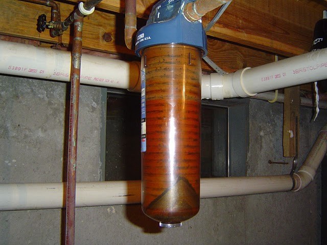
- From the main pipes, various dirt and rust gets into the heating radiators. Steel and cast iron radiators continue to work without any changes. But in aluminum batteries, the ingress of rust and dirt has a detrimental effect on the work.
- Although the coolant goes through all the required desalination and cleaning, it still passes through the rusty main pipelines. Accordingly, the coolant cannot be of good quality. This factor is a big disadvantage, since the coolant goes to water supply.
- Due to repair work, pressure drops in the system or even water hammer often occur. Such problems can seriously affect the operation of modern radiators.
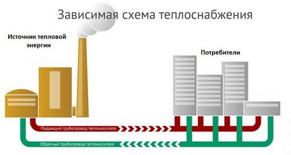
Dependent open heating system
The main feature of the dependent system is that the coolant flowing through the main networks directly enters the house. It is called open because the coolant is taken from the supply pipeline to provide the house with hot water. Most often, such a scheme is used when connecting multi-apartment residential buildings, administrative and other public buildings to heating networks. The operation of the dependent heating system circuit is shown in the figure:
At a temperature of the coolant in the supply pipeline up to 95 ºС, it can be directed directly to the heating devices. If the temperature is higher and reaches 105 ºС, then a mixing elevator unit is installed at the entrance to the house, whose task is to mix the water coming from the radiators into the hot coolant in order to lower its temperature.
The scheme was very popular in the days of the USSR, when few people were concerned about energy consumption. The fact is that the dependent connection with the elevator mixing units works quite reliably and practically does not require supervision, and installation work and material costs are quite cheap. Again, there is no need to lay additional pipes to supply hot water to houses when it can be successfully taken from the heating main.
But this is where the positive aspects of the dependent scheme end. And there are much more negative ones:
- dirt, scale and rust from the main pipelines safely gets into all consumer batteries. Old cast-iron radiators and steel convectors did not care about such trifles, but modern aluminum and other heating devices were definitely not good enough;
- due to a decrease in water intake, repair work and other reasons, there is often a pressure drop in the dependent heating system, and even water hammer. This threatens with consequences for modern batteries and polymer pipelines;
- the quality of the coolant leaves much to be desired, but it goes directly to the water supply. And, although in the boiler house water goes through all stages of purification and desalination, kilometers of old rusty highways make themselves felt;
- it is not easy to regulate the temperature in rooms. Even full bore thermostatic valves quickly fail due to poor quality of the coolant.
Connection according to the dependent scheme
It can be performed in two versions: directly or using a mixing unit. If the connection is made according to the first option, then the overheated water from the heating networks is mixed in the boiler (in a certain volume) with the returning water from the heating system. In this way, the water reaches a sufficient temperature, up to about 1000. Its value depends on the power of the boiler. The temperature may be higher. Then it enters the heating source. Heat points are supplied with pump mixers and water-jet elevators. To create the optimal air temperature in the premises, low temperature water is added to the pipeline, reducing the temperature regime. The second connection option implies that hot and cold water is mixed, and the coolant fluid with a temperature of 70-800C is sent to the heating radiators of residential buildings.
Dependent wiring diagram. Click on the photo to enlarge.
Direct connection can be used directly in low temperature heating networks, where a two-pipe system with radiator throttling thermostats is made. Here, the parameters of the coolants are constant throughout the year. Heating networks reflect changes in consumer demand in thermal volume, through devices showing the pressure drop at the inlets. With their help, electronic controllers change the flow of common pumps in the heating network.
This system can only be regulated quantitatively. The circulation of the heat source of the dependent circuit is carried out through the differences in the values of the water pressure in the areas of connection to the elements of the external heating system. The dependent connection and its connection scheme with the water mixing unit are structurally simple and easy to maintain.
The cost of the circuit is greatly reduced by the exclusion of some structural elements. The dependent scheme is selected if the heat-consuming system, including the heating system (according to sanitary and hygienic recommendations), allows an increase in hydraulic pressure to the value of water pressure outside when entering the heat pipe. For some time, the dependent scheme was popular in Russia, due to the ratio of its pros and cons.
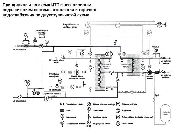
Independent heating system unit. Click on the photo to enlarge.