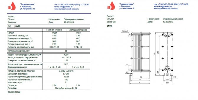
Calculation of the heat exchanger currently takes no more than five minutes. Any organization that manufactures and sells such equipment, as a rule, provides everyone with its own selection program. You can download it for free from the company's website, or their technician will come to your office and install it for free. However, how correct is the result of such calculations, is it possible to trust it and is the manufacturer not cunning when fighting in a tender with its competitors? Checking an electronic calculator requires knowledge or at least an understanding of the calculation methodology for modern heat exchangers. Let's try to figure out the details.
What is a heat exchanger
Before calculating the heat exchanger, let's remember, what kind of device is it? A heat and mass exchange apparatus (aka a heat exchanger, aka a heat exchanger, or TOA) is a device for transferring heat from one heat carrier to another. In the process of changing the temperatures of the coolants, their densities and, accordingly, the mass indicators of substances also change. That is why such processes are called heat and mass transfer.
Main menu
Hello! A heat exchanger is a device in which heat exchange is carried out between two or more heat carriers or between heat carriers and solids (nozzle, wall). The role of the coolant can also be played by the environment surrounding the apparatus. According to their purpose and design, heat exchangers can be very different, ranging from the simplest (radiator) to the most advanced (boiler unit). According to the principle of operation, heat exchangers are divided into recuperative, regenerative and mixing.
Recuperative devices are called devices in which hot and cold heat carriers flow simultaneously, separated by a solid wall. These devices include heaters, boiler units, condensers, evaporators, etc.
Apparatus in which the same heating surface is alternately washed by hot and cold liquid are called regenerative. In this case, the heat accumulated by the walls of the apparatus during their interaction with the hot liquid is given off to the cold liquid. An example of regenerative apparatuses are air heaters of open-hearth and blast furnaces, heating furnaces, etc. In regenerators, heat exchange always occurs in non-stationary conditions, while recuperative apparatuses mostly operate in a stationary mode.
Recuperative and regenerative devices are also called surface, since the process of heat transfer in them is inevitably associated with the surface of a solid.
Mixers are devices in which heat transfer is carried out by direct mixing of hot and cold liquids.
The mutual movement of heat carriers in heat exchangers can be different (Fig. 1.).

Depending on this, a distinction is made between devices with direct flow, counter-flow, cross-flow and with a complex direction of movement of heat carriers (mixed current). If the coolants flow in parallel in one direction, then such a movement pattern is called forward flow (Fig. 1.). With counterflow, the coolants move in parallel, but towards each other. If the directions of movement of fluids intersect, then the pattern of movement is called cross-flow. In addition to the named schemes, more complex ones are also used in practice: simultaneous forward flow and counterflow, multiple cross current, etc.
Depending on the technological purpose and design features, heat exchangers are subdivided into water heaters, condensers, boiler units, evaporators, etc. But the common thing is that they all serve to transfer heat from one heat carrier to another, therefore, the basic provisions of thermal calculation are the same for them. ... The difference can only be the final settlement purpose. When designing a new heat exchanger, the calculation task is to determine the heating surface; in the verification thermal calculation of the existing heat exchanger, it is required to find the amount of heat transferred and the final temperatures of the working fluids.
The heat calculation in both cases is based on the heat balance equations and the heat transfer equation.
The heat balance equation of the heat exchanger has the form:
where M is the mass flow rate of the coolant, kg / s; cpm - specific mass isobaric average heat capacity of the coolant, J / (kg * ° С).
Hereinafter, the subscript "1" denotes the values related to the hot liquid (primary heat carrier), and the subscript "2" - to the cold liquid (secondary heat carrier); the line corresponds to the temperature of the liquid at the inlet to the apparatus, and two lines - at the outlet.
When calculating heat exchangers, the concept of the total heat capacity of the mass flow rate of the heat carrier (water equivalent) is often used, equal to C = Mav W / ° C. From expression (1) it follows that
that is, the ratio of temperature changes of single-phase heat transfer fluids is inversely proportional to the ratio of their total consumption heat capacities (water equivalents).
The heat transfer equation is written as follows: Q = k * F * (t1 — t2), where t1, t2 are the temperatures of the primary and secondary heat carriers; F is the heat transfer surface area.
During heat exchange, in most cases, the temperatures of both heat carriers change and, therefore, the temperature head Δt = t1 — t2 changes. The heat transfer coefficient over the heat exchange surface will also have a variable value, therefore, the average values of the temperature difference Δtav and the heat transfer coefficient kcp should be substituted into the heat transfer equation, that is
Q = kсp * F * Δtcp (3)
The heat exchange area F is calculated by the formula (3), while the thermal performance Q is specified. To solve the problem, it is necessary to calculate the heat transfer coefficient averaged over the entire surface kсp and temperature head Δtav.
When calculating the average temperature difference, it is necessary to take into account the nature of the change in the temperatures of the heat carriers along the heat exchange surface. It is known from the theory of thermal conductivity that in a plate or a cylindrical rod in the presence of a temperature difference at the ends (the side surfaces are insulated), the temperature distribution along the length is linear. If heat exchange takes place on the lateral surface or the system has internal sources of heat, then the temperature distribution is curvilinear. With a uniform distribution of heat sources, the change in temperature along the length will be parabolic.
Thus, in heat exchangers, the nature of the change in the temperatures of the heat carriers differs from the linear one and is determined by the total heat capacities C1 and C2 of the mass flow rates of the heat carriers and the direction of their mutual movement (Fig. 2).
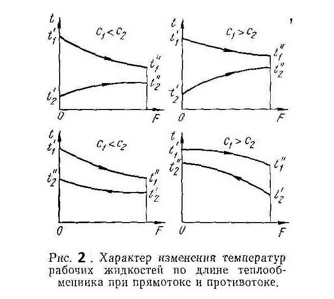
It can be seen from the graphs that the change in temperature along the surface F is not the same. In accordance with equation (2), the greater the temperature change will be for the heat carrier with the lower heat capacity of the mass flow rate. If the coolants are the same, for example, in a water-to-water heat exchanger, then the nature of the change in the temperatures of the coolants will be entirely determined by their flow rates, and at a lower flow rate, the temperature change will be large.With co-flow, the final temperature t "2 of the heated medium is always less than the temperature t" 1 of the heating medium at the outlet of the apparatus, and with counterflow, the final temperature t "2 may be higher than the temperature t" 1 (see for counterflow the case when C1> C2). Consequently, at the same initial temperature, the medium to be heated with countercurrent flow can be heated to a higher temperature than with cocurrent flow.
With cocurrent flow, the temperature head along the heating surface changes to a greater extent than with counterflow. At the same time, its average value in the latter case is greater, as a result of which the heating surface of the apparatus with counterflow will be smaller. Thus, under equal conditions, in this case, more heat will be transferred. Based on this, preference should be given to devices with a counterflow.
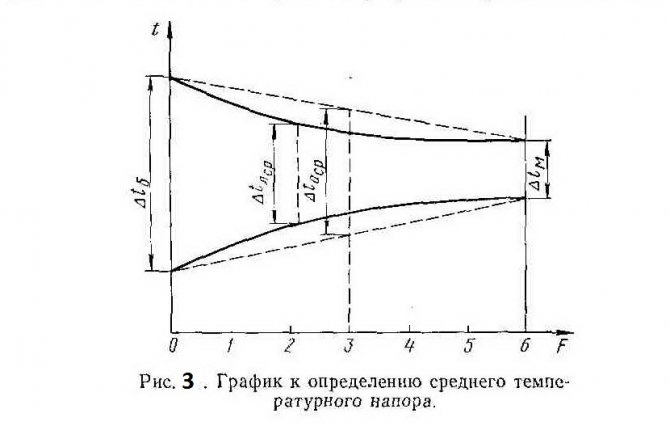
As a result of an analytical study of a heat exchanger operating according to the direct flow scheme, it was found that the temperature head along the heat exchange surface changes exponentially, so the average temperature head can be calculated by the formula:
where Δtb is the large temperature difference between the hot and cold heat carrier (from one end of the heat exchanger); Δtm - smaller temperature difference (from the other end of the heat exchanger).
With a forward flow, Δtb = t'1 - t'2 and Δtm = t "1 - t" 2 (Fig. 2.). This formula is also valid for counterflow with the only difference that for the case when C1
The average temperature difference between two media, calculated by the formula (4), is called the mean logarithmic. temperature head. The form of the expression is due to the nature of the temperature change along the heating surface (curvilinear dependence). If the dependence were linear, then the temperature head should be determined as an arithmetic mean (Fig. 3.). The value of the arithmetic mean head Δtа.av is always greater than the mean logarithmic Δtl.av. However, in cases where the temperature head along the length of the heat exchanger changes insignificantly, that is, the condition Δtb / Δtm <2 is satisfied, the average temperature difference can be calculated as an arithmetic mean:
The averaging of the temperature difference for devices with cross and mixed currents is distinguished by the complexity of calculations, therefore, for a number of the most common schemes, the results of solutions are usually given in the form of graphs. Isp. Literature: 1) Fundamentals of heat power engineering, A.M. Litvin, Gosenergoizdat, 1958.2) Teplotekhnika, Bondarev V.A., Protskiy A.E., Grinkevich R.N. Minsk, ed. 2nd, "Higher school", 1976. 3) Heat engineering, ed. 2, under the general editorship of. IN Sushkina, Moscow "Metallurgy", 1973.
Types of heat transfer
Now let's talk about the types of heat transfer - there are only three of them. Radiation - the transfer of heat through radiation. As an example, you can think of sunbathing on the beach on a warm summer day. And such heat exchangers can even be found on the market (tube air heaters). However, most often for heating living quarters, rooms in an apartment, we buy oil or electric radiators. This is an example of another type of heat transfer - convection. Convection can be natural, forced (exhaust hood, and there is a recuperator in the box) or mechanically induced (with a fan, for example). The latter type is much more efficient.
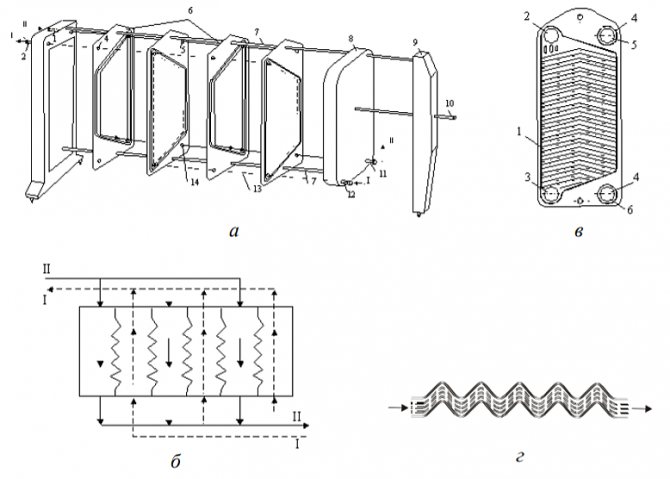
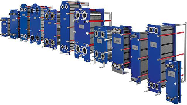
However, the most efficient way of transferring heat is thermal conductivity, or, as it is also called, conduction (from the English conduction - "conduction"). Any engineer who is going to carry out a thermal calculation of a heat exchanger, first of all, thinks about choosing efficient equipment in the smallest possible dimensions. And this is achieved precisely due to thermal conductivity. An example of this is the most efficient TOA today - plate heat exchangers. Plate TOA, by definition, is a heat exchanger that transfers heat from one coolant to another through the wall separating them. The maximum possible contact area between two media, together with correctly selected materials, the profile of the plates and their thickness, allows you to minimize the size of the selected equipment while maintaining the original technical characteristics required in the technological process.
Heat exchanger types
Before calculating the heat exchanger, they are determined with its type. All TOA can be divided into two large groups: recuperative and regenerative heat exchangers. The main difference between them is as follows: in recuperative TOA, heat exchange occurs through a wall separating two coolants, and in regenerative TOA, the two media have direct contact with each other, often mixing and requiring subsequent separation in special separators. Regenerative heat exchangers are divided into mixing and heat exchangers with packing (stationary, falling or intermediate). Roughly speaking, a bucket of hot water put out in the cold, or a glass of hot tea set to cool in the refrigerator (never do that!) Is an example of such a mixing TOA. And by pouring tea into a saucer and cooling it in this way, we get an example of a regenerative heat exchanger with a nozzle (the saucer in this example plays the role of a nozzle), which first contacts the ambient air and takes its temperature, and then takes some of the heat from the hot tea poured into it. , seeking to bring both media into thermal equilibrium. However, as we have already found out earlier, it is more efficient to use thermal conductivity to transfer heat from one medium to another, therefore, TOA that are more useful in terms of heat transfer (and widely used) today are, of course, recuperative.
Determination of the amount of heat
The heat transfer equation used for steady-state units of time and processes is as follows:
Q = KFtcp (W)
In this equation:
- K is the value of the heat transfer coefficient (expressed in W / (m2 / K));
- tav - the average difference in temperature indicators between different heat carriers (the value can be given both in degrees Celsius (0С) and in kelvin (K));
- F is the value of the surface area for which heat transfer occurs (the value is given in m2).
The equation allows you to describe the process during which heat is transferred between heat carriers (from hot to cold). The equation takes into account:
- heat transfer from the coolant (hot) to the wall;
- wall thermal conductivity parameters;
- heat transfer from the wall to the coolant (cold).
Thermal and structural calculation
Any calculation of a recuperative heat exchanger can be made based on the results of thermal, hydraulic and strength calculations. They are fundamental, mandatory in the design of new equipment and form the basis of the calculation method for subsequent models of the line of the same type of apparatus. The main task of the thermal calculation of TOA is to determine the required area of the heat exchange surface for stable operation of the heat exchanger and maintaining the required parameters of the media at the outlet. Quite often, in such calculations, engineers are given arbitrary values of the mass and size characteristics of the future equipment (material, pipe diameter, plate dimensions, beam geometry, type and material of finning, etc.), therefore, after the thermal one, a constructive calculation of the heat exchanger is usually carried out. Indeed, if at the first stage the engineer calculated the required surface area for a given pipe diameter, for example, 60 mm, and the length of the heat exchanger thus turned out to be about sixty meters, then it is more logical to assume a transition to a multi-pass heat exchanger, or to a shell-and-tube type, or to increase the diameter of the tubes.
Heat transfer mechanisms in the calculation of heat exchangers
The three main types of heat transfer are convection, heat conduction and radiation.
In heat exchange processes proceeding in accordance with the principles of the mechanism of heat conduction, heat energy is transferred in the form of transfer of energy of elastic atomic and molecular vibrations. The transfer of this energy between different atoms is in the direction of decreasing.
The calculation of the characteristics of the transfer of thermal energy according to the principle of thermal conductivity is carried out according to the Fourier law
Data on surface area, thermal conductivity, temperature gradient, flow period are used to calculate the amount of heat energy.The concept of a temperature gradient is defined as the change in temperature in the direction of heat transfer by one or another unit of length.
The thermal conductivity is the rate of the heat exchange process, i.e. the amount of thermal energy passing through any unit of surface per unit of time.
As you know, metals are characterized by the highest coefficient of thermal conductivity relative to other materials, which must be taken into account in any calculations of heat exchange processes. As for liquids, they, as a rule, have a relatively lower coefficient of thermal conductivity compared to bodies in a solid state of aggregation.
It is possible to calculate the amount of transferred thermal energy for calculating heat exchangers, in which heat energy is transferred between different media through the wall, using the Fourier equation. It is defined as the amount of heat energy passing through a plane that is characterized by a very small thickness:
After performing some mathematical operations, we get the following formula
It can be concluded that the temperature drop inside the wall is carried out in accordance with the law of a straight line.
Hydraulic calculation
Hydraulic or hydromechanical, as well as aerodynamic calculations are carried out in order to determine and optimize the hydraulic (aerodynamic) pressure losses in the heat exchanger, as well as to calculate the energy costs to overcome them. The calculation of any path, channel or pipe for the passage of the coolant poses a primary task for a person - to intensify the heat transfer process in this area. That is, one medium should transmit, and the other should receive as much heat as possible at the minimum interval of its flow. For this, an additional heat exchange surface is often used, in the form of a developed surface ribbing (to separate the boundary laminar sublayer and enhance flow turbulization). The optimal balance ratio of hydraulic losses, heat exchange surface area, weight and size characteristics and removed heat power is the result of a combination of thermal, hydraulic and constructive calculation of TOA.
Verification calculation
Calculation of the heat exchanger is carried out in the case when it is necessary to lay a margin for power or for the area of the heat exchange surface. The surface is reserved for various reasons and in different situations: if this is required according to the terms of reference, if the manufacturer decides to add an additional margin in order to be sure that such a heat exchanger will go into operation, and to minimize errors made in the calculations. In some cases, redundancy is required to round off the results of design dimensions, in others (evaporators, economizers), a surface margin is specially introduced into the calculation of the heat exchanger's capacity for contamination with compressor oil present in the refrigeration circuit. And the low quality of water must be taken into account. After some time of uninterrupted operation of heat exchangers, especially at high temperatures, scale settles on the heat exchange surface of the apparatus, reducing the heat transfer coefficient and inevitably leading to a parasitic decrease in heat removal. Therefore, a competent engineer, when calculating the water-to-water heat exchanger, pays special attention to additional redundancy of the heat exchange surface. The verification calculation is also carried out in order to see how the selected equipment will work in other, secondary modes. For example, in central air conditioners (air supply units), first and second heating heaters, used in the cold season, are often used in the summer to cool the incoming air by supplying cold water to the tubes of the air heat exchanger.How they will function and what parameters they will give out allows you to evaluate the verification calculation.
Device and principle of operation
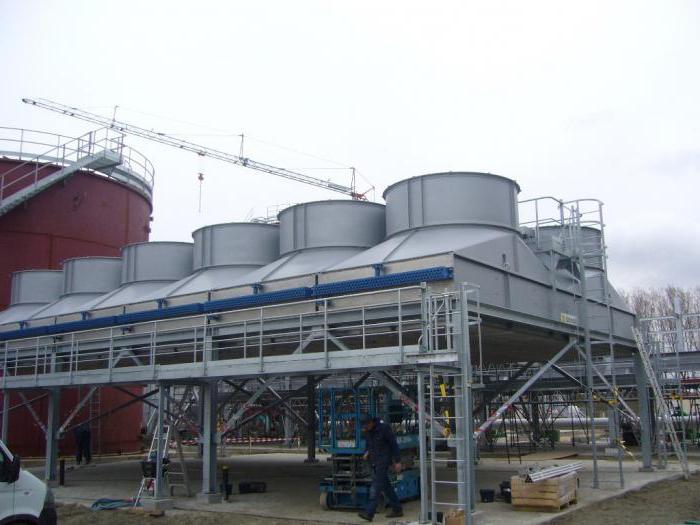
Heat exchange equipment on the modern market is presented in a wide variety.
The entire available assortment of products of this line can be divided into two types, such as:
- plate aggregates;
- shell-and-tube devices.
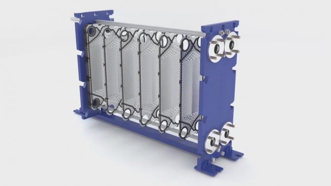
The latter variety, due to its low efficiency rate, as well as its large size, is almost not sold on the market today. The plate heat exchanger consists of identical corrugated plates that are fixed to a sturdy metal frame. The elements are located in a mirror image relative to each other, and between them there are steel and rubber seals. The effective heat exchange area directly depends on the size and number of plates.
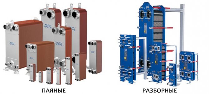
Plate devices can be divided into two subspecies based on configuration, such as:
- brazed units;
- gasketed heat exchangers.
Collapsible devices differ from products of a soldered assembly type in that, as soon as necessary, the device can be upgraded and adjusted to personal needs, for example, add or remove a certain number of plates. Gasketed heat exchangers are in demand in areas where hard water is used for domestic needs, due to the features of which drink and various contaminants accumulate on the elements of the unit. These neoplasms adversely affect the efficiency of the device, therefore, they need to be regularly cleaned, and thanks to their configuration, this is always possible.
Non-dismountable devices are distinguished by the following features:
- high level of resistance to high pressure and temperature fluctuations;
- long service life;
- light weight.
The brazed assemblies are cleaned without disassembling the entire structure.
Based on the calculation of the type and installation option of the unit, two types of heat exchangers for hot water from heating should be distinguished.
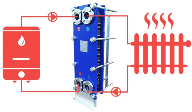
- Internal heat exchangers are located in the heating devices themselves - furnaces, boilers and others. Installation of this kind allows you to get maximum efficiency during the operation of products, since the heat loss for heating the case will be minimal. As a rule, such devices are already built into the boiler at the stage of manufacturing the boilers. This greatly facilitates installation and commissioning, since you only need to adjust the required mode of operation of the heat exchanger.
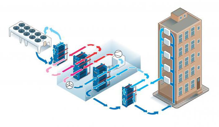
- External heat exchangers must be connected separately from the heat source. Such devices are relevant for use in cases where the operation of the device depends on a remote heating source. Houses with centralized heating are an example. In this embodiment, the household unit that heats the water acts as an external device.
Taking into account the type of material from which partings are made, it is worth highlighting the following models:
- steel heat exchangers;
- devices made of cast iron.
In addition, copper brazed systems stand out. They are used for district heating in apartment buildings.
The following characteristics should be considered the features of cast iron equipment:
- the raw material cools rather slowly, which saves on the operation of the entire heating system;
- the material has high thermal conductivity, all cast iron products have inherent properties in which it heats up very quickly and gives off heat to other elements;
- the raw material is resistant to the formation of scale on the base, in addition, it is more resistant to corrosion;
- by installing additional sections, you can increase the power and functionality of the unit as a whole;
- products from this material can be transported in parts, breaking it into sections, which facilitates the delivery process, as well as installation and maintenance of the heat exchanger.
We suggest that you familiarize yourself with: Which side to put the vapor barrier a - DOLGOSTROI.PRO
Like any other product, such a dependent device has the following disadvantages:
- cast iron is notable for its low resistance to sharp temperature fluctuations, such phenomena can be fraught with the formation of cracks on the device, which will negatively affect the performance of the heat exchanger;
- even having large dimensions, cast iron units are very fragile, therefore mechanical damage, especially during the transportation of products, can seriously damage it;
- the material is prone to dry corrosion;
- the large mass and dimensions of the device sometimes complicate the development and installation of the system.
Steel heat exchangers for hot water supply are notable for the following advantages:
- high thermal conductivity;
- small mass of products. Steel does not make the system heavier, therefore such devices are the best option when a heat exchanger is needed, whose task is to service a large area;
- steel units are resistant to mechanical stress;
- the steel heat exchanger does not react to temperature fluctuations inside the structure;
- the material has good elasticity characteristics, however, prolonged contact with a highly heated or cooled medium can lead to the formation of cracks in the area of welds.
The disadvantages of devices include the following features:
- susceptibility to electrochemical corrosion. Therefore, with constant contact with an aggressive environment, the operating life of the device will be significantly reduced;
- devices do not have the ability to increase work efficiency;
- the steel unit loses heat very quickly, which is fraught with increased fuel consumption for productive operation;
- low level of maintainability. It is almost impossible to repair the device with your own hands;
- the final assembly of the steel heat exchanger is carried out in the conditions of the workshop where it was manufactured. The units are monolithic blocks of large sizes, due to which there are difficulties with their delivery.
Some manufacturers, in order to increase the quality of steel heat exchangers, cover its inner walls with cast iron, thereby increasing the reliability of the structure.
Modern heat exchangers are units whose operation is based on different principles:
- irrigation;
- submersible;
- brazed;
- superficial;
- collapsible;
- ribbed-lamellar;
- mixing;
- shell-and-tube and others.
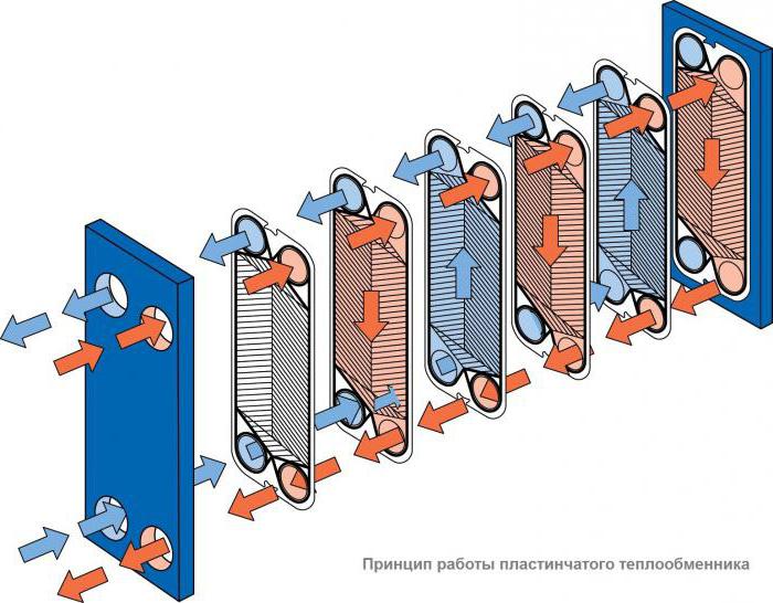
But plate heat exchangers for hot water supply and heating differ favorably from a number of others. These are flow-through heaters. Installations are a series of plates, between which two channels are formed: hot and cold. They are separated by a steel and rubber gasket, so mixing of the media is eliminated.
The plates are assembled into one block. This factor determines the functionality of the device. The plates are identical in size, but located at a turn of 180 degrees, which is the reason for the formation of cavities through which liquids are transported. This is how the alternation of cold and hot channels is formed and a heat exchange process is formed.
Recirculation in this type of equipment is intensive. The conditions in which the heat exchanger for hot water supply systems will be used depends on the material of the gaskets, the number of plates, their size and type. Installations that prepare hot water are equipped with two circuits: one for DHW, the other for space heating. Plate machines are safe, productive and used in the following areas:
- preparation of a heat carrier in hot water supply, ventilation and heating systems;
- cooling of food products and industrial oils;
- hot water supply for showers at enterprises;
- for the preparation of the heat carrier in underfloor heating systems;
- for the preparation of a heat carrier in food, chemical and pharmaceutical industries;
- pool water heating and other heat exchange processes.
Research calculations
Research calculations of TOA are carried out on the basis of the obtained results of thermal and verification calculations. As a rule, they are necessary for making the latest amendments to the design of the projected apparatus. They are also carried out in order to correct any equations laid down in the implemented calculation model TOA, obtained empirically (according to experimental data). Performing research calculations involves tens, and sometimes hundreds of calculations according to a special plan developed and implemented in production according to the mathematical theory of experiment planning. According to the results, the influence of various conditions and physical quantities on the performance indicators of TOA is revealed.
Other calculations
When calculating the area of the heat exchanger, do not forget about the resistance of materials. The TOA strength calculations include checking the designed unit for stress, torsion, for applying the maximum permissible operating moments to the parts and assemblies of the future heat exchanger. With minimal dimensions, the product must be durable, stable and guarantee safe operation in various, even the most stressful operating conditions.
Dynamic calculation is carried out in order to determine the various characteristics of the heat exchanger at variable modes of its operation.
Tube-in-tube heat exchangers
Let's consider the simplest calculation of a pipe-in-pipe heat exchanger. Structurally, this type of TOA is simplified as much as possible. As a rule, a hot coolant is let into the inner pipe of the apparatus to minimize losses, and a cooling coolant is launched into the casing, or into the outer pipe. The task of the engineer in this case is reduced to determining the length of such a heat exchanger based on the calculated area of the heat exchange surface and given diameters.
It should be added here that the concept of an ideal heat exchanger is introduced in thermodynamics, that is, an apparatus of infinite length, where the coolants work in a counterflow, and the temperature difference is fully triggered between them. The tube-in-tube design comes closest to meeting these requirements. And if you run the coolants in a counterflow, then it will be the so-called "real counterflow" (and not crossflow, as in plate TOA). The temperature head is most efficiently triggered with such an organization of movement. However, when calculating a pipe-in-pipe heat exchanger, one should be realistic and not forget about the logistics component, as well as the ease of installation. The length of the eurotruck is 13.5 meters, and not all technical rooms are adapted to the skidding and installation of equipment of this length.
How to calculate the heat exchanger
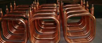
It is imperative to calculate the coil heat exchanger, otherwise its thermal power may not be enough to heat the room. The heating system is designed to compensate for heat loss. Accordingly, we can only find out the exact amount of required heat energy based on the heat loss of the building. It is quite difficult to make a calculation, therefore, on average, they take 100 W per 1 square meter with a ceiling height of 2.7 m.
There must be a gap between the turns.
Also, the following values are required for the calculation:
- Pi;
- the diameter of the pipe that is available (take 10 mm);
- lambda thermal conductivity of metal (for copper 401 W / m * K);
- the delta of the supply and return temperature of the coolant (20 degrees).
To determine the length of the pipe, you need to divide the total thermal power in W by the product of the above factors.Let us consider using the example of a copper heat exchanger with a required thermal power of 3 kW - this is 3000 W.
3000 / 3.14 (Pi) * 401 (thermal conductivity lambda) * 20 (temperature delta) * 0.01 (pipe diameter in meters)
From this calculation, it turns out that you need 11.91 m of copper pipe with a diameter of 10 mm for the heat output of the coil to be 3 kW.
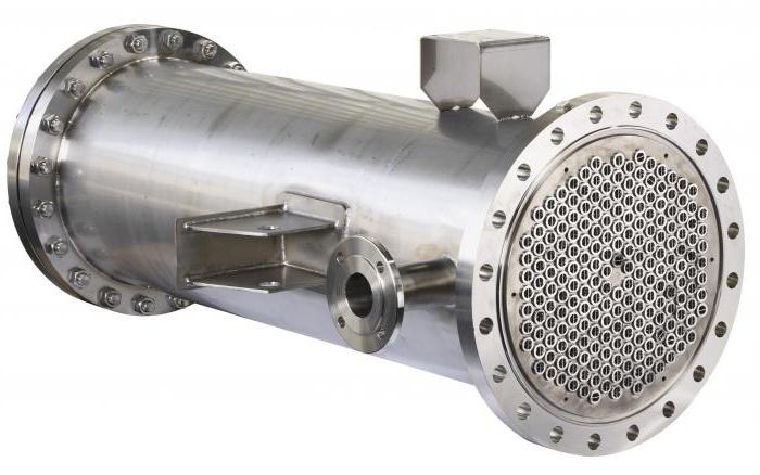
Shell and tube heat exchangers
Therefore, very often the calculation of such an apparatus smoothly flows into the calculation of a shell-and-tube heat exchanger. This is an apparatus in which a bundle of pipes is located in a single casing (casing), washed by various coolants, depending on the purpose of the equipment. In condensers, for example, the refrigerant is run into the jacket and the water into the pipes. With this method of moving the media, it is more convenient and efficient to control the operation of the apparatus. In evaporators, on the contrary, the refrigerant boils in the tubes, and at the same time they are washed by the cooled liquid (water, brines, glycols, etc.). Therefore, the calculation of a shell-and-tube heat exchanger is reduced to minimizing the size of the equipment. While playing with the diameter of the casing, the diameter and number of inner pipes and the length of the apparatus, the engineer reaches the calculated value of the area of the heat exchange surface.
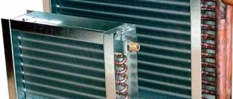
Air heat exchangers
One of the most common heat exchangers today is the finned tubular heat exchangers. They are also called coils. Wherever they are not installed, starting from fan coil units (from the English fan + coil, ie "fan" + "coil") in the internal blocks of split systems and ending with giant flue gas recuperators (heat extraction from hot flue gas and transfer it for heating needs) in boiler plants at CHP. This is why the design of a coil heat exchanger depends on the application where the heat exchanger will go into operation. Industrial air coolers (VOPs), installed in blast freezing chambers of meat, in freezers of low temperatures and at other objects of food refrigeration, require certain design features in their performance. The distance between the lamellas (fins) should be as large as possible to increase the continuous operation time between defrost cycles. Evaporators for data centers (data processing centers), on the contrary, are made as compact as possible, clamping the spacing to a minimum. Such heat exchangers operate in "clean zones" surrounded by fine filters (up to the HEPA class), therefore, such a calculation of the tubular heat exchanger is carried out with an emphasis on minimizing the size.
Types of coil heat exchangers
A heated towel rail is also a coil heat exchanger.
You can make a coil with your own hands of different designs and from several types of metal (steel, copper, aluminum, cast iron). Aluminum and cast iron products are stamped in factories, since the required conditions for working with these metals can only be achieved in production conditions. Without this, it will be possible to work only with steel or copper. It is best to use copper as it is malleable and has a high degree of thermal conductivity. There are two schemes for making a coil:
- screw;
- parallel.
The helical scheme implies the location of the spiral turns along a helical line. The coolant in such heat exchangers moves in one direction. If necessary, to increase the heat output, several spirals can be combined according to the "pipe in pipe" principle.
To minimize heat loss as much as possible, you need to choose what kind of insulation is best to insulate the house from the outside. It also depends on the material of the walls.
It is necessary to make the choice of insulation for a wooden house based on the vapor permeability of the thermal insulation.
In a parallel circuit, the coolant constantly changes its direction of movement. Such a heat exchanger is made of straight pipes connected by a 180 degree elbow.In some cases, for example, for the manufacture of a heating register, swivel knees may not be used. Instead of them, a direct bypass is installed, which can be located both at one and at both ends of the pipe.
Heat transfer methods
The principle of operation of a coil heat exchanger is to heat one substance at the expense of the heat of another. Thus, the water in the heat exchanger can be heated by an open flame. In this case, it will act as a heat sink. But also the coil itself can act as a heat source. For example, when a coolant flows through the tubes, heated in a boiler or by means of a built-in electric heating element, and its heat is transferred to water from the heating system. Basically, the ultimate purpose of heat transfer is to heat the indoor air.
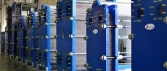
Plate heat exchangers
Currently, plate heat exchangers are in stable demand. According to their design, they are completely collapsible and semi-welded, copper-brazed and nickel-brazed, welded and brazed by the diffusion method (without solder). The thermal design of a plate heat exchanger is flexible enough and not particularly difficult for an engineer. In the selection process, you can play with the type of plates, the punching depth of the channels, the type of ribbing, the thickness of steel, different materials, and most importantly - numerous standard-size models of devices of different dimensions. These heat exchangers are low and wide (for steam heating of water) or high and narrow (separating heat exchangers for air conditioning systems). They are often used for phase change media, that is, as condensers, evaporators, desuperheaters, pre-condensers, etc. It is a little more difficult to perform the thermal calculation of a heat exchanger operating in a two-phase scheme than a liquid-to-liquid heat exchanger, but for an experienced engineer, this task is solvable and not particularly difficult. To facilitate such calculations, modern designers use engineering computer bases, where you can find a lot of necessary information, including diagrams of the state of any refrigerant in any scan, for example, the CoolPack program.