Installation features
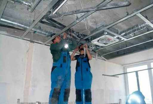
Taking into account the complexity of fan coil-chiller systems, its installation and adjustment should be carried out by highly professional specialists. Only they will be able to perform high-quality installation of fan coil units by making competent:
- installation of the unit in the place where its work will be as efficient as possible;
- assembly of piping units by installing the necessary taps, valves, temperature and pressure control devices;
- laying and thermal insulation of pipes;
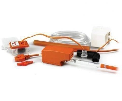
- installation of a condensate drainage system;
- work on connecting devices to the mains;
- pressure testing of the system and checking its tightness;
- media (water) feed.
They will also make all the necessary calculations before starting work, taking into account what functional load this or that fan coil will perform, as well as the features of each room in the structure.
Thus, you were able to make sure not only that the fan coil-chiller systems are very effective, economical and reliable, but also that they require complex installation and commissioning operations. And this requires the involvement of employees of organizations specializing in the creation of such turnkey systems.
How do these devices work?
Principle of operation
The air drawn by the fan through the fan coil heat exchanger is heated or cooled, depending on which operating mode is selected. In this case, the air flow is created not from the air mass that is present in the room, but from fresh air supplied from a special machine - a chiller, which is the central unit when creating an air conditioning system or heating all rooms in a building using fan coils. The air enters the chiller from the air supply unit, which produces air intake from the street.
What is the advantage of such a centralized air conditioning system?
Typical malfunctions
Repair of fan coil units is necessary in the event of the following malfunctions:
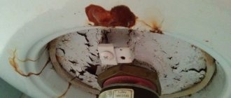
- Dirty filters, preventing the system from operating at full capacity. Cleaning the fan coil units and air conditioner shafts is a mandatory activity that takes place twice a year before the heating and cooling season. The first sign is an unpleasant odor, when it appears, the wizards are called to diagnose the system. The malfunction does not require dismantling, the work is carried out on site.
- Wear of parts. Constant intensive work leads to premature equipment failure. Defective air conditioner parts break faster. Depending on the location of the faulty structure, problems are eliminated on site or at a service.
- High humidity and mold. The first sign is that condensation begins to accumulate inside the room, the windows fog up. Cleaning and disinfection of the ventilation shaft is required. Fluid leaks can cause similar fan coil malfunctions. The dirt that accumulates in the heat exchanger is a breeding ground for microorganisms.
- Increased vibration, extraneous sounds during work.
- No cooling or heating while the system is running.
In order not to bring the equipment to obvious errors, it is necessary to inspect for potential problems long before they appear.
Varieties of fan coil units
Today, there are four main types of such equipment:
- Cantilever frameless.
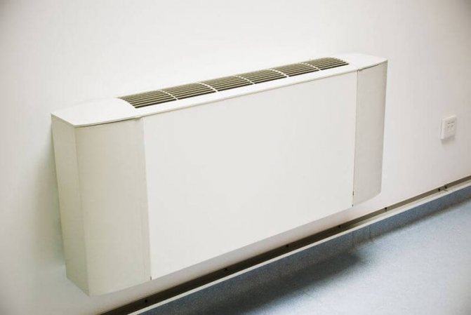
- Console in the case.
- Horizontal.
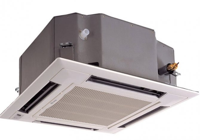
- Fan coil unit cassette.
Depending on the installation, each type of this climatic equipment can be wall-mounted, floor-mounted, ceiling-mounted or built-in.Depending on the tasks, fan coil units can be equipped with two or four-pipe piping. When using two-pipe piping, the device can only work for cooling or heating the air in the room. The use of a four-pipe piping makes it possible to use both a cold and a hot circuit of the chiller, while operating the unit for both heating and cooling, making settings from the control panel. Due to the complexity in implementation, the cost of installing fan coil units with a four-pipe piping is significantly higher than with a two-pipe piping.


The role of fan coil in the air conditioning system
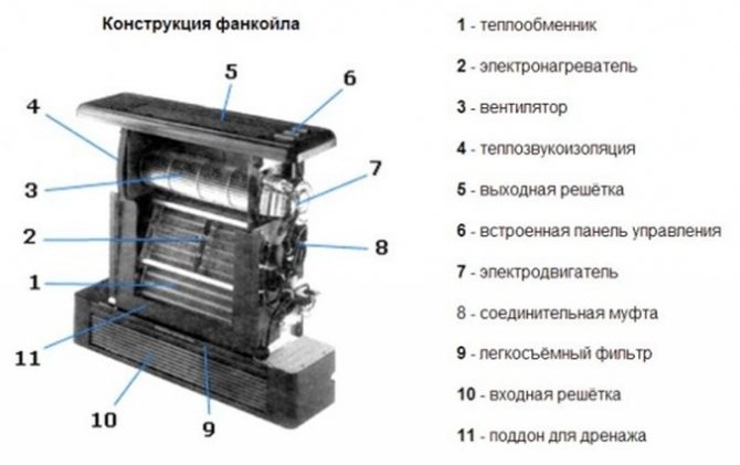
A fan coil unit is an important element of a centralized climate control system. The second name is a fan coil. If the term fan-coil is literally translated from English, then it sounds like a fan-heat exchanger, which most accurately conveys the principle of its operation.
The fan coil unit is designed with a network module for connection to a central control unit. The robust housing hides the structural elements and protects them from damage. Outside, a panel is installed that evenly distributes air flows in different directions
The purpose of the device is to accept low temperature media. The list of its functions also includes both recirculation and cooling of air in the room where it is installed, without the intake of air from the outside. The main elements of the fan-coil are located in its body.
These include:
- centrifugal or cross-flow fan;
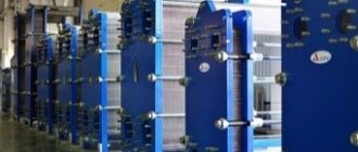
- a heat exchanger in the form of a coil, consisting of a copper tube and aluminum fins, mounted on it;
- dust filter;
- Control block.
In addition to the main units and parts, the fan coil design includes a sump for collecting condensate, a pump for pumping out the latter, an electric motor, through which the air dampers are turned.
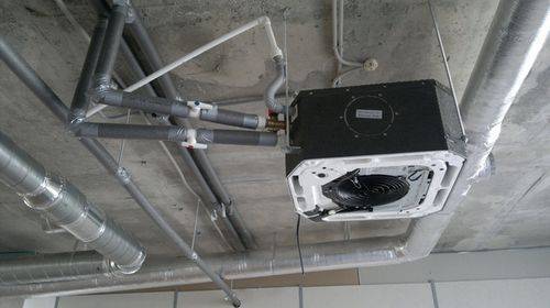
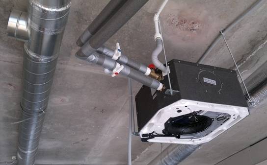
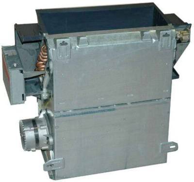
Pictured is a Trane duct fan coil unit. The productivity of double-row heat exchangers is 1.5 - 4.9 kW. The unit is equipped with a low-noise fan and a compact housing. It fits perfectly behind false panels or suspended ceiling structures
Depending on the method of installation, there are ceiling ‚duct‚ fan coil units mounted in ducts through which the air flow is carried out ‚open frame, where all the elements are mounted on a frame‚ wall or console.
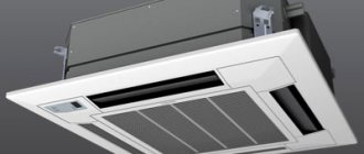
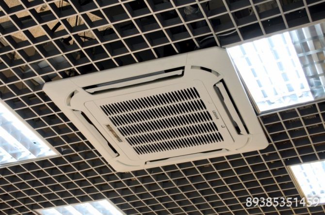
Ceiling devices are the most popular and have 2 versions: cassette and duct. The first ones are mounted in large rooms with false ceilings. A body is placed behind the suspended structure. The bottom panel remains visible. They can disperse air currents on two or all four sides.
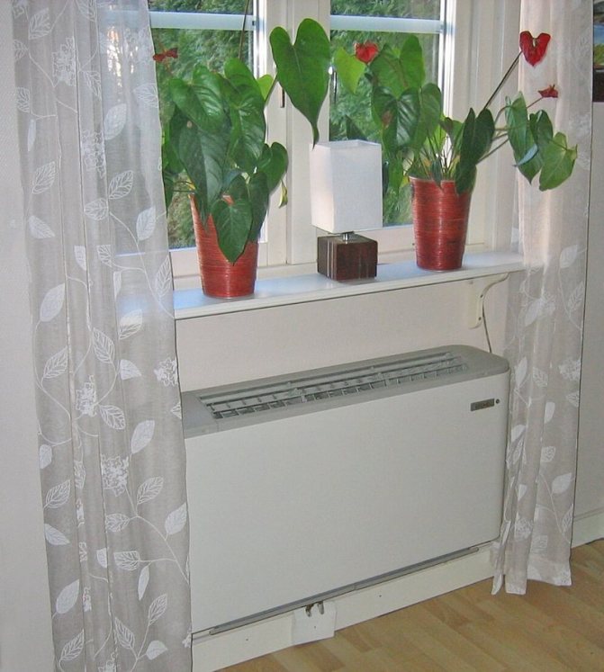
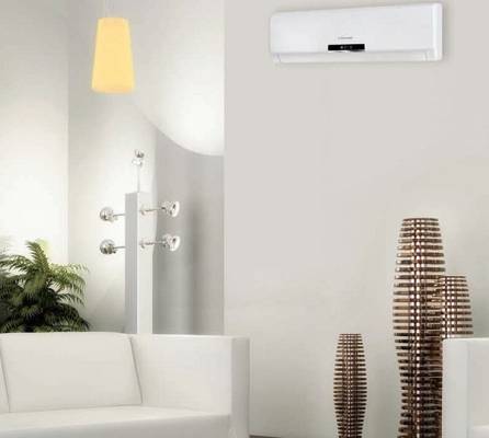
If the system is going to be used exclusively for cooling, then the best place for it is the ceiling. If the structure is intended for heating, the device is placed on the wall at the bottom of it
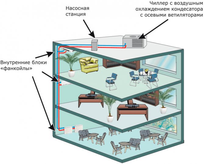
The need for cooling does not always exist, therefore, as can be seen in the diagram, transmitting the principle of operation of the chiller-fincoil system, a tank is built into the hydraulic module, which acts as an accumulator for the refrigerant. The thermal expansion of the water is compensated for by an expansion vessel connected to the supply line.
Fan coil units are controlled in both manual and automatic modes. If the fan coil operates for heating, then the cold water supply is cut off in manual mode. When operating it for cooling, hot water is blocked and a path is opened for the flow of the cooling working fluid.
Remote control for both 2-pipe and 4-pipe fan coil units. The module is connected directly to the device and placed close to it. The control panel and wires for its power supply are connected from it.
To work in automatic mode, the panel is set to the temperature required for a particular room.The set parameter is maintained by means of thermostats, which adjust the circulation of heat carriers - cold and hot.
The advantage of a fan coil is expressed not only in the use of a safe and cheap heat carrier, but also in the quick elimination of problems in the form of water leaks. This makes their service cheaper. The use of these devices is the most energy efficient way to create a favorable microclimate in a building.
Since any large building has zones with different temperature requirements, each of them must be served by a separate fan coil or a group of them with identical settings.
The number of units is determined at the design stage of the system by calculation. The cost of individual units of the chiller-fan coil system is quite high, therefore, both the calculation and the design of the system must be carried out as accurately as possible.
Classification
You will be able to determine for yourself which devices are most suitable for you for installation, knowing their parameters and performance characteristics.
Currently, you can choose from four different fan coil designs:
- Console type.
- Console type in the case.
- Cassette type.
- Horizontal type.
All these types of heat exchangers can be installed in a room in a variety of ways:
- hang on the wall;
- to be installed simply on the floor of the room;
- be built into the ventilation system of the building;
- installed in suspended ceiling structures.
The main characteristics of a fan coil unit that affect the choice of a particular device are:
- cold air performance;
- overall air capacity.
Connecting a cassette fan coil unit
In addition, heat exchanger systems using water as a carrier can be:
- Two-pipe. This strapping scheme is the simplest and most common. It only allows you to cool the air in the room. Therefore, the cost of such a device will be low. In winter, two-pipe fan coil units can be switched to heating mode, but for this the pipes must be disconnected from the chiller and connected to the central heating system. This function is performed by a special manually adjustable valve.
- Four-pipe. This system includes two heat exchangers, one of which is connected to the chiller, and the other to the hot medium system (central heating system). This strapping scheme is more complex. Therefore, the price of such a fan coil will be higher. This system allows you to either cool the air in the room or heat it without making complex switching of pipes, but only by selecting the required mode on the control panel of the device. Such fan coil units are best mounted in the area of windows, since this will compensate for heat loss through the glass.
The main classes of chillers
The conditional division of chillers into classes occurs depending on the type of refrigeration cycle. On this basis, all chillers can be conditionally classified into two classes - absorption and steam compressor.
Absorption unit design
An absorption chiller or ABCM for operation uses a binary solution with water and lithium bromide present in it - an absorber. The principle of operation is the absorption of heat by the refrigerant in the phase of converting steam into a liquid state. Such units use the heat generated during the operation of industrial equipment. In this case, an absorbent absorber with a boiling point significantly higher than the corresponding parameter of the refrigerant ‚dissolves the latter well.
The operation diagram of a chiller of this class is as follows:
- Heat from an external source is supplied to a generator, where it heats up a mixture of lithium bromide and water. When the working mixture boils, the refrigerant (water) completely evaporates.
- The vapor is transferred to the condenser and becomes a liquid.
- Liquid refrigerant enters the throttle. Here it cools down and the pressure drops.
- The liquid enters the evaporator, where the water evaporates and its vapors are absorbed by the lithium bromide solution - the absorber. The air in the room is cooled.
- The diluted absorbent is reheated in the generator and the cycle is restarted.
Such an air conditioning system has not yet become widespread, but it is completely in tune with modern trends in energy saving, therefore, it has good prospects.
Work of vapor compression units
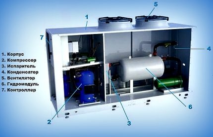
Most refrigeration units operate on the basis of compression refrigeration. Cooling occurs due to continuous circulation, boiling at low temperatures, pressure and condensation of the refrigerant in a closed-loop system. The chiller of this class includes:
- compressor;
- evaporator;
- capacitor;
- pipelines;
- flow regulator.
The refrigerant circulates in a closed system. This process is controlled by a compressor, in which a gaseous substance with a low temperature (-5⁰) and a pressure of 7 atm is compressed when the temperature is brought to 80⁰. Dry saturated vapor in a compressed state goes into the condenser, where it is cooled to 45⁰ at a constant pressure and converted into liquid.
The next item on the way is the throttle (pressure reducing valve). At this stage, the pressure decreases from the value of the corresponding condensation to the limit at which evaporation occurs. At the same time, the temperature drops to approximately 0⁰. The liquid partially evaporates and moist vapor is formed.
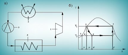
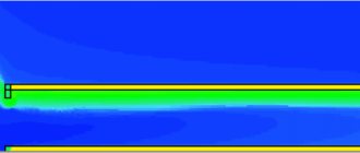
The diagram shows a closed cycle according to which the vapor compression unit operates. In the compressor (1), wet saturated steam is compressed until it reaches a pressure p1. In the compressor (2), the steam gives off heat and is transformed into liquid. In the throttle (3), both the pressure (p3 - p4) and the temperature (T1-T2) decrease. In the heat exchanger (4), the pressure (p2) and temperature (T2) remain unchanged
Having entered the heat exchanger - the evaporator ‚the working substance‚ a mixture of vapor and liquid ‚gives cold to the coolant and takes heat from the refrigerant‚ drying out at the same time. The process takes place at constant pressure and temperature. The pumps deliver low temperature liquid to the fan coil units. Having passed this way, the refrigerant returns to the compressor in order to repeat the entire vapor compression cycle again.
What a vapor compression chiller can do
In cold weather, the chiller can operate in natural cooling mode - this is called freecooling. In this case, the coolant cools the outside air. In theory, free cooling can be used at ambient temperatures of less than 7 ° C. In practice, the optimum temperature for this is 0⁰.
When set to heat pump mode, the chiller operates for heating. The cycle is undergoing changes, in particular, the condenser and the evaporator exchange their functions. In this case, the coolant must be subjected not to cooling, but to heating.
The simplest are monoblock chillers. They compactly combine all the elements into one whole. They go on sale 100% complete up to refrigerant charge
This mode is most often used in large offices ‚public buildings‚ in warehouses. The chiller is a refrigeration unit that gives 3 times more cold than it consumes. Its efficiency as a heater is even higher - it consumes 4 times less electricity than it generates heat.
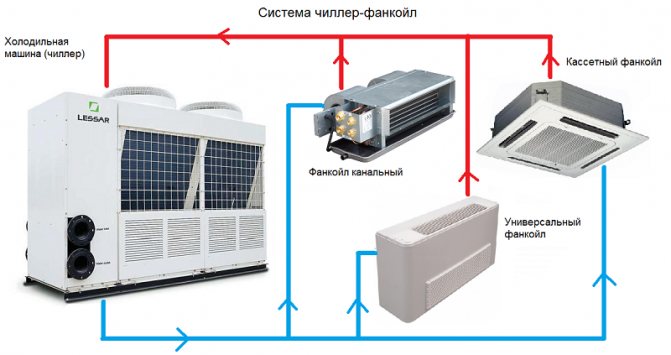
Chillers and fan coil units for central air conditioning systems
A chiller-fan coil unit is a type of air conditioning device, a distinctive feature of which is the circulation between blocks of water (ethylene glycol / propylene glycol) as a refrigerant.
Chiller is a refrigeration machine that lowers the temperature of the liquid inside the coolant. Installed on the roof, attic space, technical room. When installing the machine on a roof, it is necessary to drain the water from the system before the onset of the cold season.
Fan coil is an internal unit of the device equipped with a fan (fan), a heat exchanger (coil). Outwardly, it is very similar to a split-system block.

The equipment can operate in three modes: cooling, heating, cooling-heating (4-pipe piping).
Indoor unit modifications:
- wall
- cassette
- duct
- floor and ceiling.
Let's briefly present the installation diagrams.
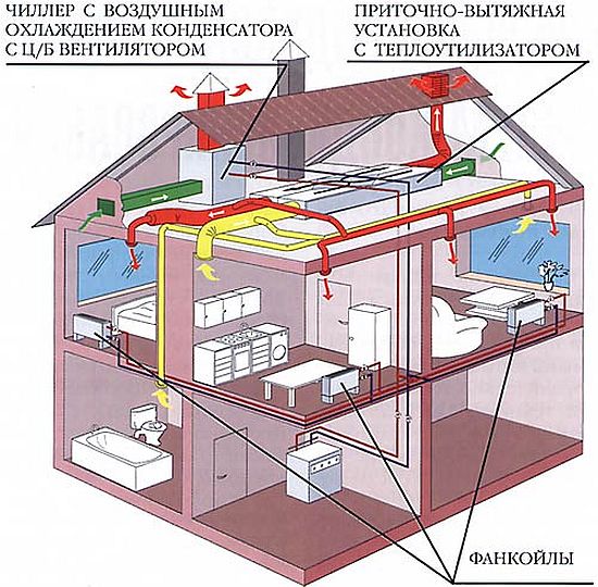
Components of the chiller-fan coil diagram
The role of the cooling device is assigned to the chiller - an external unit that produces and supplies cold through pipelines with water or ethylene glycol circulating through them. This is what distinguishes this system from other split systems, where freon is pumped as a coolant, for the transmission of which expensive copper pipes are needed. Here, water pipes with thermal insulation do an excellent job with this task.
Its operation is not affected by the outside air temperature, while split systems with freon lose their performance already at -10⁰. The indoor heat exchanger is a fan coil unit. It receives a liquid with a low temperature, then transfers the cold to the air in the room, and the heated liquid returns back to the chiller.
Fan coil units are installed in all rooms. Each of them works according to an individual program.
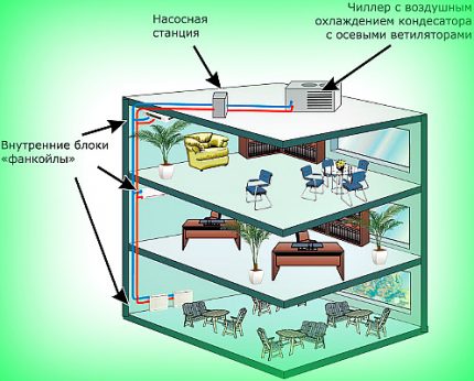
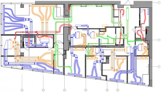
The photo shows the main elements of the system - a pumping station, a chiller, a fan coil. The fan coil unit can be installed at a great distance from the chiller. It all depends on how strong the pump is. The number of fan coil units is proportional to the chiller capacity
Typically, such systems are used in hypermarkets, shopping malls, underground structures, hotels. They are sometimes used for heating purposes. Then, along the second circuit, heated water is supplied to the fan coil units or the system is switched to the heating boiler.
Stages of installation work
Installation of the chiller-fan coil system is carried out in the following sequence:
- The chiller is installed in a technical room or on the roof.
- The installation site is determined according to the plan. The indoor unit case is fixed to the wall, ceiling or ventilation.
- The units are connected to air ducts. For duct models, valves are installed that regulate the supply of fresh air.
- The piping units are assembled near the fan coil units, sensors and taps are installed.
- Pipes are laid and thermal insulation is done.
- The drainage is discharged into the sewerage system.
- The system is connected to the mains.
- First start-up and tightness test - pressure test.
- Filling pipes with coolant and final testing of the facility.
- Drawing up an act of completed work.
Dismantling is carried out in the following sequence:
- overlapping nodes near fan coil units;
- disconnection from the water supply system;
- overlapping drainage;
- disconnection from the network.
If you plan to replace fan coil units, the pipe diameters of the old and new systems are taken into account.
Types of installation of fan coil units
The basic diagram of a fan coil unit provides:
- the presence of a pipeline that transports hot or cold water, depending on the tasks in a certain period of time - winter, summer;
- the presence of a chiller that prepares the required water temperature and creates a flow of fresh air taken from the street;
- internal devices (fan coils) through which the room temperature is controlled.
Internal climatic devices:
- Cassette. Installed behind false ceilings. Suitable for large areas in shopping centers, industrial premises.
- Duct. Found in ventilation shafts.
- Wall mounted.A good choice for small spaces - apartments, offices.
- Floor and ceiling. Suitable for placement under ceilings or near walls.
Installation of chillers and fan coil units of various types has its own characteristics, as well as advantages and disadvantages:
- The duct is capable of performing three functions (cooling, heating, ventilation), but it requires accurate calculations of the consumed air volume, expert advice in terms of installing a water heating system for the winter period.
- Installation of cassette-type fan coil units saves space, air conditioning large rooms, but requires space under the ceiling, which is allocated for the installation of the unit.
- Installation of floor-type fan coil units makes it possible to quietly cool rooms of complex design, without affecting human health, but requires more power and space on the floor or under the ceiling.
- Connecting a wall-mounted fan coil is the least economical way, but easier.
Systems are two-pipe and four-pipe. The price of a four-pipe wiring is higher, since it simultaneously carries out both heating and cooling. The two-pipe system is cheaper, but for the heating function it will be necessary to divert the pipes from the refrigeration unit and connect to the boiler during the heating season.
Duct fan coils are mounted using the hidden connection method. The section in the ceiling must be movable to access the device.
Cassette, floor and wall units are mounted in an open way. Open type devices are easier to operate and maintain.
Installation benefits
Above, we have already talked about the advantages of the system itself. We especially note once again that it is not difficult to mount it.
The cost of the components is low. It is easy to maintain and repair. In addition, it can be designed for any type of building.
Application area
Basically, devices of this type are used in:
- In office premises.
- Hospitals.
- Supermarkets and other retail outlets.
- Hotel complexes.
The cost
The price of the product depends on the cost of the components, that is, the chiller and the fan coil unit.
For example, let's give the cost of two products.
Fan coil unit TRUST- 12678 rubles.
Homo series– 15609.
The fixtures are randomly selected. At the same time, the first unit also has higher productivity and it serves a large area of the premises, but the price for it is lower than that of the second.
Hence the conclusion: the main factor that determines the price of the unit is the manufacturer.
Features of operation
The main feature of servicing this type of unit is to charge the device with refrigerant. In this case, you must strictly follow the instructions set out in the technical documentation of the device. In all other respects, the system is maintained in the same way as similar units.
Stages of installation work
Fan coil installation works can be roughly divided into several stages:
- The correct choice of installation site.
- Fastening the device to the enclosing structures.
- Creation of a strapping node.
- Laying of a pipeline for supply and discharge of working fluids.
- Installation and connection of the drainage system.
- Connection of power supply and control system.
- Checking the tightness of the system.
- Setting up work.
Despite the difference in design, the installation work of fan coil units is almost the same.
It should be understood that the quality and durability of the entire system directly depends on the competent installation of fan coil units, therefore it is best to entrust the implementation of such work to professionals
When contacting a company for the installation and maintenance of such climatic equipment, you should pay attention to the experience of specialists and the availability of the necessary equipment in the company
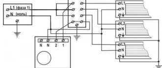
Installation of electrical wiring diagram for fan coil units
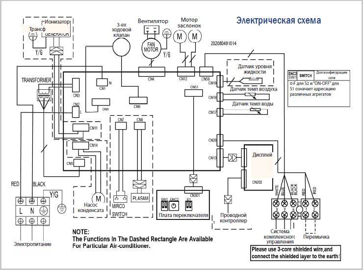
Wiring diagram for wall fan coil unit
Before starting work, you need to familiarize yourself with the wiring diagram. Electrical equipment must be grounded.
Requirements for connecting fan coil units to the mains:
- use the cable according to the recommendations in the manual;
- organize a separate power supply with the required voltage;
- connect all wires directly to the shield, including grounding;
- the water circuit must be on the opposite side of the terminal box;
- the elements of the hydraulic circuit must not come into contact with the wires.
The unit starts up after an insulation test. The direction of rotation of the fan impeller, the operation of the drain pump, if available, the electric heater are checked separately.
The act is drawn up based on the test results. At the same time, an agreement is signed with the company for continuous service.
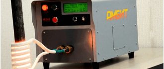
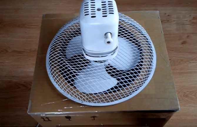
How to make a Fan coil unit with your own hands
The device and the number of components of the fan coil are quite modest, with good performance indicators. For the production of a Fancoil with your own hands you need:
- fan
- power supply controller with timer
- a few old boxes
- pan
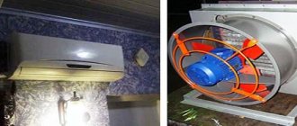
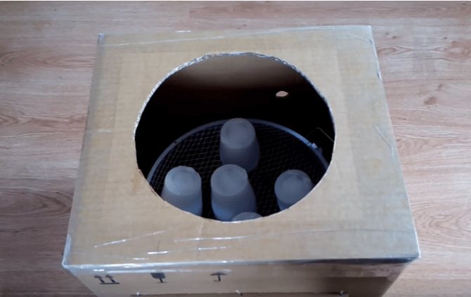
Let's get started. First, we will prepare the fan, remove all decorative elements from it, leaving only the rotating mechanism itself with the shell.
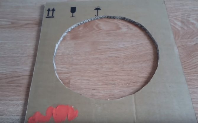
Then we prepare a box, you can take an old one from under a shoe, a microwave oven, or from a fan you just bought. The choice should fall on the box, based on the distance between the floor and the battery in the place where the homemade fan coil is installed. We make two holes in the box, in one the device will be attached and a cord with a power plug will come out, on the other side, cut out a hole through which the wind generated will blow the battery.
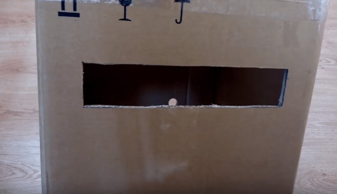
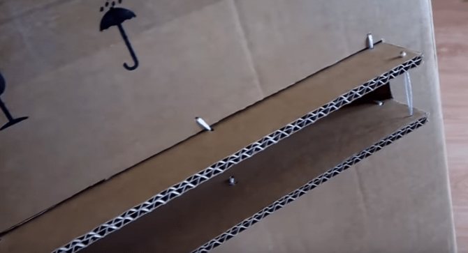

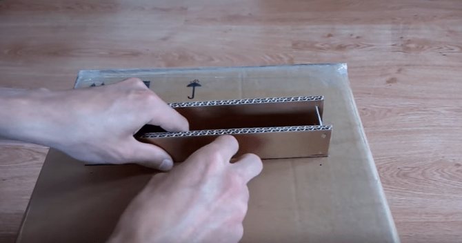
When mounting and mounting in a box, take into account the fact that the motor itself from the mechanism must be outside the box to prevent overheating. It is also advisable to install the motor as low as possible from the battery, but so that it does not touch any surfaces, including the floor.
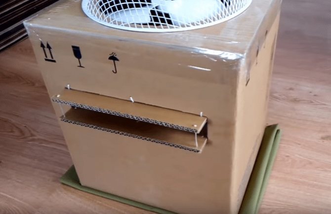
We do not connect the power cord with a plug directly to the outlet, as this will lead to endless functioning and its quick failure. To save ourselves from this trouble, we have prepared a power controller with a timer that will independently turn it on and off at a time set by the owner.
A homemade fan coil unit of this type will raise the temperature by several degrees. With such a low cost and a feeling of discomfort at a low degree index, you can easily sacrifice aesthetic appearance on the coldest days. And the mobility of this design makes it easy to get and hide the device as needed.
Video: Homemade powerful air conditioner for the room
Installation
Installation of chillers and fan coil units consists of several main stages:
- First, the device is mounted indoors.
- Then the strapping unit is assembled.
- Installation of pipelines and thermal insulation to them is in progress.
- Air ducts are laid and their sound insulation is organized.
- A drainage system is being created.
- The equipment is connected to the mains.
- Check the tightness.
- Start the system.
Mounting by device type
Floor
The easiest installation process is to install a floor-standing fan coil unit without a condensate duct. They do not spoil the interior and can be installed independently. The typical design of such equipment consists of two nozzles through which the mixer and the working fluid go.
Cassette, wall and sub-ceiling
Installation of the cassette fan coil unit and the other two is a little more difficult, since they can be either two-pipe or four-pipe. However, their electrical system may differ significantly from floor systems.
Therefore, it is best to entrust the installation of a wall-mounted fan coil unit, under-ceiling and cassette, to specialists.
With the help of specialists
Connecting a fan coil is a complex process that requires a professional approach, so it is best to contact a specialist.Only they will be able to competently do the work on:
- installing the unit in the most efficient place;
- assembly of piping units by installing the necessary taps, temperature and pressure control devices, valves;
- laying and thermal insulation of pipes;
- installation of condensate drain;
- connecting devices to the electrical network;
- pressure testing of the system;
- tightness check;
- water supply.
They will do all the calculations before starting work and will take into account the characteristics of the room and the load of each fan coil. Specialists will create a safe and reliable system that will serve the user for a long time.
What to remember when contacting specialists
In order to correctly select a company that provides installation services, you should pay attention to the following criteria:
- great experience;
- high-quality equipment and spare parts;
- the company carries out all stages of installation: from thermal calculation to checking the operation of the system.
It will be difficult for an untrained customer to control the correctness of the process and compliance with all requirements if he does not have special knowledge. And in the absence of knowledge about a specific model, you can easily break the device.
Fan coil connection in several stages
First stage
- this is the installation of the fan coil itself in the place allocated in the project with its subsequent connection to the pipeline system supplying water (or any other coolant). Again, all the characteristics inherent in the project should be taken as a basis.
- It is impossible to change or change the diameters of the pipelines, the material from which the pipes should be made, which will definitely affect the flow rate of the coolant through the fan coil and, in the future, on the operability of the chiller itself.
- Do not allow the installation of valves, adapters or other elements of the hydraulic circuit that are not provided for by the project, as well as the installation of the same elements.
- It must be remembered that when the fan coil is in operation, condensate forms on its heat exchanger and this condensate must be discharged into the sewage system.
- To avoid stagnation of condensate in the drainage pipelines during its laying, it is imperative to maintain a slope of 1 degree along the entire length of the drainage pipeline.
- Completely eliminate failures and the formation of stagnant zones.
- There are unpleasant odors in the sewage system and the ingress of these odors through the drainage pipeline into the fan coil unit, and then into the room, must also be excluded by providing a water seal or odor-locking device on the drainage pipeline.
Second phase.
Since ducted fan coil units are of different types of location, the most difficult thing at this stage is to connect the fan coil units to the air ducts.
- Not all ducted fan coil units can be connected to air ducts, so this stage is more for those who have such a connection. If the duct fan coil requires the connection of air ducts, then at this stage such a connection is made through which air flows to the fan coil itself, and through which the prepared air enters the room after the fan coil. In addition, it is necessary to pay attention to the air duct that provides the flow of fresh air, if such is included in the project.
- The material and cross-section of the air ducts are different and therefore these parameters of the air ducts should be observed in accordance with what is laid down in the project documentation.
- Attention should be paid to the length of the air ducts through which air must flow from the room and into the room. This length is directly related to the technical characteristics of the fan coil unit such as static head. Increasing the length of the duct can lead to a decrease in the air flow rate.
Stage three
... The fan coil units are connected to the power supply network.
- Before connecting, it would be a good idea to take some time to check the voltage match of the fan coil unit and the network to which you want to connect.The machine through which a fan coil unit or several fan coil units should be connected should be slightly larger (by about 15-20%) in current strength (amperes) than all fan coil units connected to it. You can use the formula from the 6th class to calculate the current strength of the machine. P = U * I whence I = P / U. Where P is the electrical power of the connected fan coil units; U is the voltage in the network (usually 220 V); I is the current strength (amperes) to which the machine must correspond through which the connection is made.
- We must not forget that it is imperative to connect all three wires, especially the third - ground.
You should not trust this type of work to random people who are not certified to carry out such work, thereby remembering that "a miser pays twice."
Fan coil installation with piping
In addition to cooling, this air conditioning system is used for heating. The indoor unit is connected to the chiller and central heating system. For this, a second heat exchange circuit is used.
Depending on this, two types of strapping are distinguished:
- Two-pipe. Operation only for heating (the chiller is equipped with a heat pump) or cooling. The piping is organized by a two-pipe circuit with one heat exchanger. In this case, the device is equipped with a 2-way valve that works to open / close the fluid supply inside the heat exchanger.
- Four-pipe. Connecting a device for cooling / heating at the same time. One circuit is for connection to a chiller. The second two-pipe circuit is for connection to central heating. Thus, the device simultaneously cools and heats the premises. It is relevant for buildings where a separate setting of the temperature regime in different rooms is required.
A 3-way valve is used here, which supplies liquid bypassing the indoor unit when the heating is connected, which allows you to maintain the autonomy of the circuits with their own temperature characteristics.
The use of this device as part of central air conditioning equipment allows you to bring the quality of the cooled air to the required microclimatic indicators. The ability to connect to central heating during the cold season significantly saves energy costs. Especially important for large office buildings, business centers, large shopping areas. Installation for suburban housing is also possible.
Conclusions and useful video on the topic
Video # 1. Everything about the device, operation and principle of operation of the thermoregulation system:
Video # 2. How to install and commission the chiller:
The installation of a chiller-fan coil system is advisable in medium and large buildings with an area exceeding 300 m². For a private house, even a huge one, the installation of such a thermoregulation system is an expensive pleasure. On the other hand, such financial investments will provide comfort and well-being, and this is a lot.
Please write your comments in the block below. Ask questions on points of interest, share your own opinions and impressions. Perhaps you have experience in the field of a chiller-fan coil climate system or a photo on the topic of the article?
Today, in homes, instead of air conditioning systems, they often resort to installing fan coil units - devices that cool and heat the air in the room. The heat exchanger can be installed in different rooms of the building and set an individual temperature mode for each of them.
System testing
Before starting the operation of the fan coil system, a number of test activities must be carried out. This is necessary in order to check the operability of all elements of the equipment.
Crimping
First, you need to rinse all parts of the water supply pipeline with water. Further, the entire system is filled with water and the tightness of all joints of the system is checked. The next step is to create the appropriate pressure using a hydraulic pump.The system is under increased pressure for 5 minutes. This will help locate leaks that were not detected during the initial visual inspection.
Water start
After filling the water circuit with liquid, it is possible that air will remain in the system. Its removal is carried out during the operation of the equipment and takes a couple of hours. These actions are performed using a manual air bleed valve.
It is also mandatory to check the drainage of the fan coil unit. For this, a small amount of water is added to the condensate collection tank. The liquid should gradually drain out through the drain tube. If this does not happen, you need to check the slope angle of the drain.
Food
Connection to the power grid is possible only when all sections of the equipment wiring are checked
What you need to pay attention to:
- Rotor. The uniform air distribution and the direction of rotation of the fan are checked.
- Automatic control mechanisms.
- Electric heater.
- Condensate pump.
After a final check of all mechanisms, an appropriate document is drawn up, and the fan coil units can be operated.
The condensate pump must be checked before connecting the unit to the mains.
Features of installing fan coil units
Most often, such a technique is not installed one by one, but in groups, which are distributed over rooms and floors.
- Equipment with the same hydraulic resistance, mounted on the same floor, is installed according to the diagram shown in Figure 1.
- Equipment with the same hydraulic resistance, intended for installation on different floors, is mounted according to the diagram shown in Figure 2.
- Fan coil units with different hydraulic resistance, installed on the same floor, are mounted according to the diagram shown in Figure 3.
- Devices with different hydraulic resistance, installed on different floors, are mounted according to the diagram shown in Figure 4.
- The main advantage of schemes 1 and 2 is that there is no need to adjust the circuit with the working fluid. The advantage of schemes 3 and 4 can be considered a lower flow rate of the pipeline.
Differences in the installation of different types of indoor units
Duct fan coil unit is installed in the ventilation shaft
The scheme of a four-pipe fan coil is fundamentally different from a two-pipe scheme. In the first case, 2 circuits are connected, operating from air conditioning and heating systems. When switching modes, no additional measures are required, the task comes from the remote control. For a two-pipe system, all fluid must be drained before manual changeover. This method requires additional seasonal service and costing.
The method of installing indoor units is different if the devices are located:
- at different levels (floors), but have the same hydraulic resistance (HS);
- at the same level with the same HS;
- with different HS, but located at the same level;
- with different GEs at different levels.
Installation work should be carried out at the stage of construction or rough repair of the building. After the completion of the repair, the final measures are carried out - automatic adjustment of the equipment and the installation of decorative grilles on the cassette units.
Indoor units are installed in a case-based or open-frame method:
- Cabinet models are installed equidistantly around the entire perimeter of a room or building, regardless of the location of the rooms. This applies to a cooling-only two-pipe system.
- Open-frame models are installed mostly hidden. For open-frame units, anti-vibration mounts are provided.
Floor-standing units are considered easy to install, for which you need to install drainage with the required angle of inclination in order to avoid liquid stagnation, connect to the mains.Correctly following the instructions or focusing on the videos, you can do the work yourself.
Wall-mounted models require the help of a specialist who must:
- make the strapping correctly;
- set up control devices;
- check the pressure;
- make thermal insulation;
- lay pipes;
- make crimping;
- connect to the power supply.
For cassette models, it is necessary to provide sound insulation, vibration protection, correctly select and cut a hole in the false ceiling, then connect to the cold water supply and the heating circuit. All connections must be checked and tested before commissioning.
Shut-off valves
Three-way shut-off valve
In cooling systems, three-way and two-way shut-off valves are installed. The trim assembly 2-way valve is simpler but less reliable. It is recommended in any case to install a three-way valve. The difference is as follows:
- When using a 2-way valve, chilled liquid continues to flow into the fan coil when it is turned off, but this is done less intensively. Cooling continues after shutdown.
- The 3-way valve completely blocks the flow of refrigerant, therefore, when turned off, the system does not cool the room.