Compliance with the temperature regime is a very important technological condition not only in production, but also in everyday life. Being so important, this parameter must be regulated and controlled by something. A huge number of such devices are produced, which have many features and parameters. But making a thermostat with your own hands is sometimes much more profitable than buying a ready-made factory analogue.
Create a thermostat yourself
General concept of temperature controllers
Devices that fix and at the same time regulate a set temperature value are found to a greater extent in production. But they also found their place in everyday life. To maintain the required microclimate in the house, thermostats for water are often used. They make such devices for drying vegetables or heating an incubator with their own hands. A similar system can find its place anywhere.
In this video, we will find out what a temperature controller is:
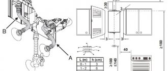
In fact, most thermostats are only part of the overall circuit, which consists of the following components:
- A temperature sensor that measures and fixes, as well as transmitting the received information to the controller. This happens due to the conversion of thermal energy into electrical signals recognized by the device. The sensor can be a resistance thermometer or thermocouple, which in their design have a metal that reacts to temperature changes and changes its resistance under its influence.
- The analytical unit is the regulator itself. It receives electronic signals and reacts depending on its functions, after which it transmits the signal to the actuator.
- An actuator is a kind of mechanical or electronic device that, when receiving a signal from the unit, behaves in a certain way. For example, when the set temperature is reached, the valve will shut off the coolant supply. Conversely, as soon as the readings fall below the preset values, the analytical unit will give the command to open the valve.
These are the three main parts of the temperature control system. Although, in addition to them, other parts, like an intermediate relay, can participate in the circuit. But they perform only an additional function.
How the finished circuit works
With the help of a transistor, a relay is turned on, which, in turn, enables the magnetic starter to turn on. Through its contacts, the heater is connected to the network with two of its own contacts. In this case, no phase remains on the load when the starter is tripped. If there is high humidity in the room, it is recommended to use an RCD for connection.
As a heater, in addition to heating elements, oil radiators, 100 W incandescent lamps and household heaters with a built-in fan are used. It is necessary to exclude direct access to live parts.
After the thermostat for turning on and off with your own hands is assembled, you should check the quality and correct installation. All connections must be well soldered. After that, you can configure the device in accordance with the specified parameters.
Principle of operation
The principle by which all regulators work is to take a physical quantity (temperature), transfer data to the control unit circuit, which decides what needs to be done in a particular case.
If you make a thermal relay, then the simplest option will have a mechanical control circuit.Here, with the help of a resistor, a certain threshold is set, upon reaching which a signal will be given to the actuator.
To get additional functionality and the ability to work with a wider temperature range, you will have to integrate the controller. This will also help to increase the life of the device.
In this video, you can watch how to make your own thermostat for electric heating:
Typical thermal relay circuit
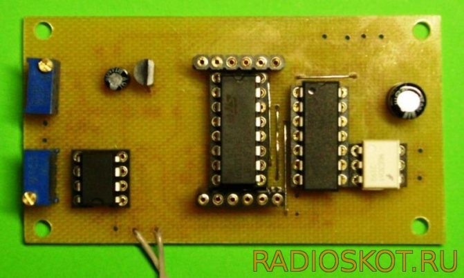
The design is based on the LM335 temperature sensor or its analogs, as well as the LM311 compressor. The thermostat circuit is supplemented by an output device to which a heater with a set power is connected. A power supply is required, if necessary, indicators can be used.
A more complex circuit includes transistors, relays, a zener diode and a capacitor C1, which smooths the voltage ripples. Equalization of the current is performed using a parametric stabilizer. In this case, the device can be powered from any source, the parameters of which coincide with the voltage of the relay coil in the range from 12 to 24 volts. The power supply can be stabilized using a conventional diode bridge with a capacitor.
Homemade temperature controller
There are actually a lot of schemes for making a thermostat yourself. It all depends on the area in which such a product will be used. Of course, creating something too complex and multifunctional is extremely difficult. But a thermostat that can be used to heat an aquarium or dry vegetables for the winter can be created with a minimum of knowledge.
This is useful: distribution manifold in the heating system.
The simplest scheme
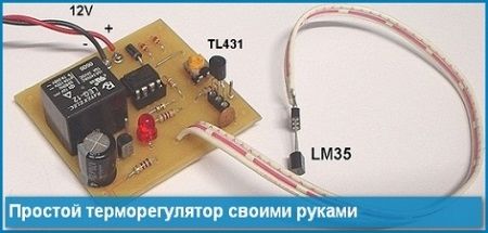
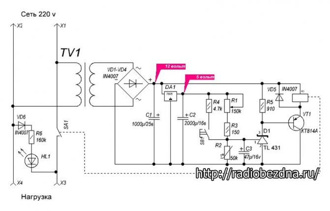
The simplest do-it-yourself thermostat circuit has a transformerless power supply, which consists of a diode bridge with a parallel connected zener diode, which stabilizes the voltage within 14 volts, and a quenching capacitor. You can also add a 12 volt stabilizer here if you wish.
The creation of a thermostat does not require much effort and money investment
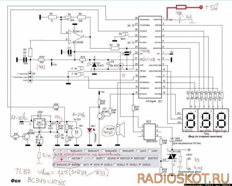
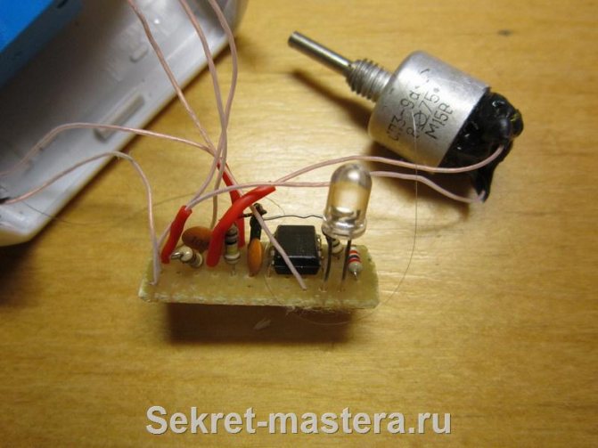
The whole circuit will be based on the TL431 Zener diode, which is controlled by a divider consisting of a 47 kΩ resistor, a 10 kΩ resistance and a 10 kΩ thermistor acting as a temperature sensor. Its resistance decreases with increasing temperature. Resistor and resistance are best matched to obtain the best response accuracy.
The process itself looks like this: when a voltage of more than 2.5 volts is formed on the control contact of the microcircuit, then it will open, which will turn on the relay, supplying a load to the actuator.
How to make a thermostat for an incubator with your own hands, you can see in the video presented:
Conversely, when the voltage drops below, the microcircuit will close and the relay will turn off.
To avoid rattling of the relay contacts, it is necessary to select it with a minimum holding current. And parallel to the inputs, you need to solder a 470 × 25 V capacitor.
When using an NTC thermistor and a microcircuit that has already been in business, it is worth checking their performance and accuracy first.
In this way, the simplest device turns outregulating the temperature. But with the right ingredients, it performs excellently in a wide range of applications.
Indoor device
Such thermostats with a do-it-yourself air temperature sensor are optimal for maintaining the specified microclimate parameters in rooms and containers. It is fully capable of automating the process and controlling any heat emitter, from hot water to heating elements. At the same time, the thermal switch has excellent performance data. And the sensor can be either built-in or remote.
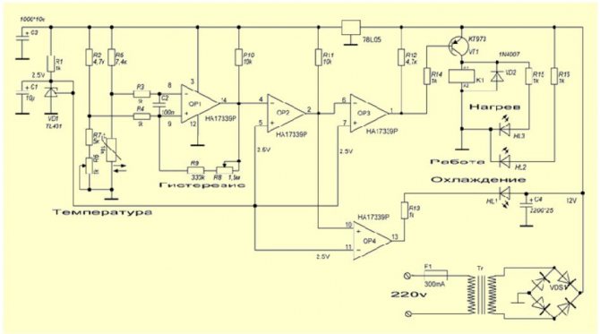
Here, a thermistor, indicated in the diagram R1, acts as a thermal sensor. The voltage divider includes R1, R2, R3 and R6, the signal from which goes to the fourth pin of the operational amplifier microcircuit. The fifth contact of DA1 receives a signal from the divider R3, R4, R7 and R8.
The resistances of the resistors must be selected in such a way that at the lowest low temperature of the measured medium, when the resistance of the thermistor is maximum, the comparator is positively saturated.
The comparator output voltage is 11.5 volts. At this time, the transistor VT1 is in the open position, and the relay K1 turns on the executive or intermediate mechanism, as a result of which heating begins. As a result, the ambient temperature rises, which lowers the resistance of the sensor. At the input 4 of the microcircuit, the voltage begins to increase and, as a result, exceeds the voltage at pin 5. As a result, the comparator enters the phase of negative saturation. At the tenth output of the microcircuit, the voltage becomes approximately 0.7 volts, which is a logical zero. As a result, the transistor VT1 closes, and the relay turns off and turns off the actuator.
On the LM 311 chip
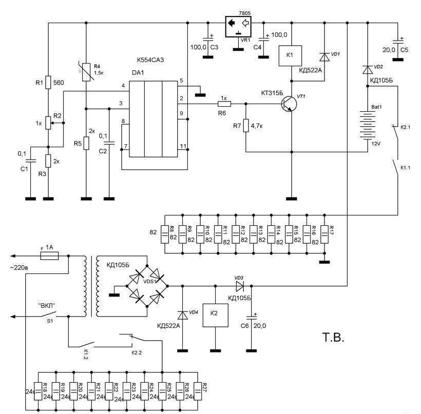
Such a do-it-yourself thermocontroller is designed to work with heating elements and is able to maintain the set temperature parameters within 20-100 degrees. This is the safest and most reliable option, since it uses galvanic isolation of the temperature sensor and control circuits, and this completely eliminates the possibility of electric shock.
Like most similar circuits, it is based on a DC bridge, in one arm of which a comparator is connected, and in the other - a temperature sensor. The comparator monitors the mismatch of the circuit and reacts to the state of the bridge when it crosses the balance point. At the same time, he also tries to balance the bridge using a thermistor, changing its temperature. And thermal stabilization can occur only at a certain value.
Resistor R6 sets the point at which balance should be formed. And depending on the temperature of the environment, the thermistor R8 can enter this balance, which allows you to regulate the temperature.
In the video, you can see an analysis of a simple thermostat circuit:
If the temperature set by R6 is lower than the required one, then the resistance on R8 is too large, which reduces the current on the comparator. This will cause current to flow and open the semiconductor VS1.which will turn on the heating element. This will be signaled by the LED.
As the temperature rises, the resistance of R8 will begin to decrease. The bridge will tend to the balance point. On the comparator, the potential of the inverse input gradually decreases, and on the direct one, it increases. At some point, the situation changes, and the process takes place in the opposite direction. Thus, the thermocontroller with its own hands will turn on or off the actuator depending on the resistance R8.
If LM311 is not available, then it can be replaced with the domestic KR554SA301 microcircuit. It turns out a simple do-it-yourself thermostat with minimal costs, high accuracy and reliability.
Simple do-it-yourself thermostat - diagram
The device of the thermostat is not particularly complicated, so many novice radio amateurs hone their skills in the manufacture of this device. Circuits are offered in a variety of ways, but the most widespread is the variant with the use of a special microcircuit called a comparator.
This element has two entrances and one exit. A certain reference voltage is supplied to one input, which corresponds to the required temperature, and to the second, the voltage from the temperature sensor.
Thermoregulator circuit for underfloor heating
The comparator compares the incoming data and, at a certain ratio, generates a signal at the output that turns on the transistor or turns on the relay. In this case, current is supplied to the heater or refrigeration unit.

Advantages and disadvantages
Even a simple do-it-yourself thermostat has a lot of advantages and positive aspects. There is no need to talk about factory multifunctional devices at all.
Temperature controllers allow:
- Maintain a comfortable temperature.
- Save energy.
- Do not involve a person in the process.
- Observe the technological process, increasing the quality.
The disadvantages include the high cost of factory models. Of course, this does not apply to home-made devices. But the production ones, which are required when working with liquid, gaseous, alkaline and other similar media, have a high cost. Especially if the device must have many functions and capabilities.