Here you will find out:
- Calculation of an air heating system - a simple technique
- The main method for calculating the air heating system
- An example of calculating heat loss at home
- Calculation of air in the system
- Air heater selection
- Calculation of the number of ventilation grilles
- Aerodynamic system design
- Additional equipment increasing the efficiency of air heating systems
- Application of thermal air curtains
Such heating systems are divided according to the following criteria: By type of energy carrier: systems with steam, water, gas or electric heaters. By the nature of the flow of the heated coolant: mechanical (with the help of fans or blowers) and natural impulse. By the type of ventilation schemes in heated rooms: direct-flow, or with partial or full recirculation.
By determining the place of heating the coolant: local (the air mass is heated by local heating units) and central (heating is carried out in a common centralized unit and subsequently transported to the heated buildings and premises).
Calculation of an air heating system - a simple technique
Air heating design is not an easy task. To solve it, it is necessary to find out a number of factors, the independent determination of which may be difficult. RSV specialists can make for you a preliminary project for air heating of a room based on GRERES equipment free of charge.
An air heating system, like any other, cannot be created at random. To ensure the medical norm of temperature and fresh air in the room, a set of equipment will be required, the choice of which is based on an accurate calculation. There are several methods for calculating air heating, of varying degrees of complexity and accuracy. A common problem with calculations of this type is that the influence of subtle effects is not taken into account, which is not always possible to foresee.
Therefore, making an independent calculation without being a specialist in the field of heating and ventilation is fraught with errors or miscalculations. However, you can choose the most affordable method based on the choice of the power of the heating system.
The meaning of this technique is that the power of heating devices, regardless of their type, must compensate for the heat loss of the building. Thus, having found the heat loss, we obtain the value of the heating power, according to which a specific device can be selected.
The formula for determining heat loss:
Q = S * T / R
Where:
- Q - the amount of heat loss (W)
- S - the area of all structures of the building (room)
- T - the difference between internal and external temperatures
- R - thermal resistance of the enclosing structures
Example:
A building with an area of 800 m2 (20 × 40 m), 5 m high, there are 10 windows measuring 1.5 × 2 m.We find the area of structures: 800 + 800 = 1600 m2 (floor and ceiling area) 1.5 × 2 × 10 = 30 m2 (window area) (20 + 40) × 2 × 5 = 600 m2 (wall area). Subtract the area of the windows from here, we get a "clean" wall area of 570 m2
In the SNiP tables, we find the thermal resistance of concrete walls, floors and floors and windows. You can determine it yourself using the formula:
Where:
- R - thermal resistance
- D - material thickness
- K - coefficient of thermal conductivity
For simplicity, we will take the thickness of the walls and floor with the ceiling to be the same, equal to 20 cm.Then the thermal resistance will be equal to 0.2 m / 1.3 = 0.15 (m2 * K) / W We will choose the thermal resistance of the windows from the tables: R = 0, 4 (m2 * K) / W The temperature difference is taken as 20 ° C (20 ° C inside and 0 ° C outside).
Then for the walls we get
- 2150 m2 × 20 ° C / 0.15 = 286666 = 286 kW
- For windows: 30 m2 × 20 ° C / 0.4 = 1500 = 1.5 kW.
- Total heat loss: 286 + 1.5 = 297.5 kW.
This is the amount of heat loss that must be compensated for with air heating with a capacity of about 300 kW.
It is noteworthy that when using floor and wall insulation, heat loss is reduced by at least an order of magnitude.
Calculation of heat loss in the house
According to the second law of thermodynamics (school physics), there is no spontaneous transfer of energy from less heated to more heated mini- or macro-objects. A special case of this law is the “striving” to create temperature equilibrium between two thermodynamic systems.
For example, the first system is an environment with a temperature of -20 ° C, the second system is a building with an internal temperature of 20 ° C. According to the above law, these two systems will strive to balance through the exchange of energy. This will happen with the help of heat losses from the second system and cooling in the first one.
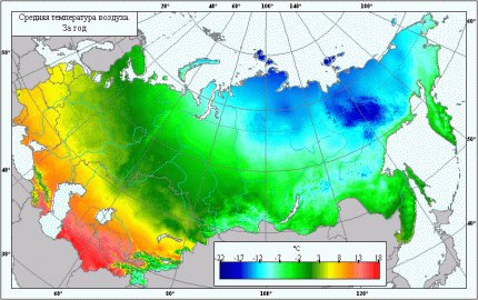
It can be said unambiguously that the ambient temperature depends on the latitude at which the private house is located. And the temperature difference affects the amount of heat leakage from the building ()
https://www.youtube.com/watch?v=QnsoSvKnuKw
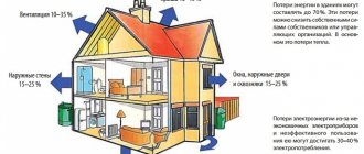
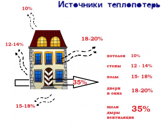
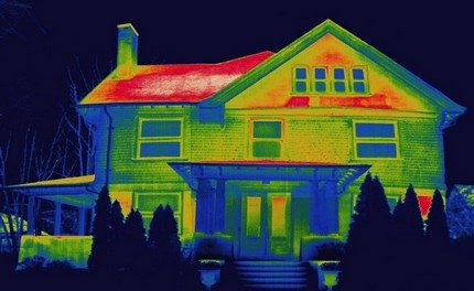
Heat loss means the involuntary release of heat (energy) from some object (house, apartment). For an ordinary apartment, this process is not so "noticeable" in comparison with a private house, since the apartment is located inside the building and is "adjacent" to other apartments.
In a private house, heat “escapes” to one degree or another through the outer walls, floor, roof, windows and doors.
Knowing the amount of heat loss for the most unfavorable weather conditions and the characteristics of these conditions, it is possible to calculate the power of the heating system with high accuracy.
Q = Qfloor Qwall Qwindow Qroof Qdoor ... Qi, where
Qi is the volume of heat loss from the uniform appearance of the building envelope.
Q = S * ∆T / R, where
- Q - thermal leaks, V;
- S is the area of a specific type of structure, sq. m;
- ∆T - temperature difference between ambient and indoor air, ° C;
- R - thermal resistance of a certain type of structure, m2 * ° C / W.
The very value of thermal resistance for actually existing materials is recommended to be taken from auxiliary tables.
R = d / k, where
- R - thermal resistance, (m2 * K) / W;
- k - coefficient of thermal conductivity of the material, W / (m2 * K);
- d is the thickness of this material, m.
In older houses with a damp roof structure, heat leakage occurs through the top of the building, namely through the roof and attic. Carrying out measures for warming the ceiling or thermal insulation of the attic roof solve this problem.
If you insulate the attic space and the roof, then the total heat loss from the house can be significantly reduced.
There are several other types of heat losses in the house through cracks in structures, a ventilation system, a kitchen hood, opening windows and doors. But it makes no sense to take into account their volume, since they make up no more than 5% of the total number of main heat leaks.
The main method for calculating the air heating system
The basic principle of operation of any SVO is to transfer thermal energy through the air by cooling the coolant. Its main elements are a heat generator and a heat pipe.
Air is supplied to the room already heated to the temperature tr in order to maintain the desired temperature tv. Therefore, the amount of accumulated energy should be equal to the total heat loss of the building, i.e. Q. The equality takes place:
Q = Eot × c × (tv - tn)
In the formula E is the flow rate of heated air kg / s for heating the room. From equality we can express Eot:
Eot = Q / (c × (tv - tn))
Recall that the heat capacity of air c = 1005 J / (kg × K).
According to the formula, only the amount of supplied air is determined, which is used only for heating only in recirculation systems (hereinafter referred to as RSCO).
In supply and recirculation systems, part of the air is taken from the street, and the other part is taken from the room. Both parts are mixed and, after heating to the required temperature, are delivered to the room.
If CBO is used as ventilation, then the amount of air supplied is calculated as follows:
- If the amount of air for heating exceeds the amount of air for ventilation or is equal to it, then the amount of air for heating is taken into account, and the system is chosen as a direct-flow system (hereinafter referred to as PSVO) or with partial recirculation (hereinafter referred to as CRSVO).
- If the amount of air for heating is less than the amount of air required for ventilation, then only the amount of air required for ventilation is taken into account, the PSVO is introduced (sometimes - RSPO), and the temperature of the supplied air is calculated by the formula: tr = tv + Q / c × Event ...
If the tr value exceeds the permissible parameters, the amount of air introduced through the ventilation should be increased.
If there are sources of constant heat generation in the room, then the temperature of the supplied air is reduced.
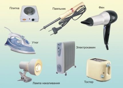
The included electrical appliances generate about 1% of the heat in the room. If one or more devices will work continuously, their thermal power must be taken into account in the calculations.
For a single room, the tr value may be different. It is technically possible to implement the idea of supplying different temperatures to individual rooms, but it is much easier to supply air of the same temperature to all rooms.
In this case, the total temperature tr is taken the one that turned out to be the smallest. Then the amount of supplied air is calculated using the formula that determines Eot.
Next, we determine the formula for calculating the volume of incoming air Vot at its heating temperature tr:
Vot = Eot / pr
The answer is recorded in m3 / h.
However, the air exchange in the room Vp will differ from the Vot value, since it must be determined based on the internal temperature tv:
Vot = Eot / pv
In the formula for determining Vp and Vot, the air density indicators pr and pv (kg / m3) are calculated taking into account the heated air temperature tr and the room temperature tv.
The room supply temperature tr must be higher than tv. This will reduce the amount of air supplied and will reduce the size of the channels of systems with natural air movement or reduce electricity costs if mechanical induction is used to circulate the heated air mass.
Traditionally, the maximum temperature of the air entering the room when it is supplied at a height exceeding 3.5 m should be 70 ° C. If the air is supplied at a height of less than 3.5 m, then its temperature is usually equal to 45 ° C.
For residential premises with a height of 2.5 m, the permissible temperature limit is 60 ° C. When the temperature is set higher, the atmosphere loses its properties and is not suitable for inhalation.
If the air-thermal curtains are located at the outer gates and openings that go outside, then the temperature of the incoming air is 70 ° C, for curtains in the outer doors, up to 50 ° C.
The supplied temperatures are influenced by the methods of air supply, the direction of the jet (vertically, inclined, horizontally, etc.). If people are constantly in the room, then the temperature of the supplied air should be reduced to 25 ° C.
After performing preliminary calculations, you can determine the required heat consumption for heating the air.
For RSVO, heat costs Q1 are calculated by the expression:
Q1 = Eot × (tr - tv) × c
For PSVO, Q2 is calculated according to the formula:
Q2 = Event × (tr - tv) × c
The heat consumption Q3 for RRSVO is found by the equation:
Q3 = × c
In all three expressions:
- Eot and Event - air consumption in kg / s for heating (Eot) and ventilation (Event);
- tn - outdoor temperature in ° С.
The rest of the characteristics of the variables are the same.
In the CRSVO, the amount of recirculated air is determined by the formula:
Erec = Eot - Event
The variable Eot expresses the amount of mixed air heated to a temperature tr.
There is a peculiarity in the PSVO with natural impulse - the amount of moving air changes depending on the outside temperature.If the outside temperature drops, the system pressure rises. This leads to an increase in the intake of air into the house. If the temperature rises, then the opposite process occurs.
Also, in SVO, in contrast to ventilation systems, air moves with a lower and varying density compared to the density of the air surrounding the air ducts.
Because of this phenomenon, the following processes occur:
- Coming from the generator, the air passing through the air ducts is noticeably cooled during movement
- With natural movement, the amount of air entering the room changes during the heating season.
The above processes are not taken into account if fans are used in the air circulation system for air circulation; it also has a limited length and height.
If the system has many branches, rather long, and the building is large and tall, then it is necessary to reduce the process of cooling the air in the ducts, to reduce the redistribution of air supplied under the influence of natural circulating pressure.
When calculating the required power of extended and branched air heating systems, it is necessary to take into account not only the natural process of cooling the air mass while moving through the duct, but also the effect of the natural pressure of the air mass when passing through the channel
To control the air cooling process, a thermal calculation of the air ducts is performed. To do this, it is necessary to set the initial air temperature and clarify its flow rate using formulas.
To calculate the heat flux Qohl through the walls of the duct, the length of which is l, use the formula:
Qohl = q1 × l
In the expression, the q1 value denotes the heat flux passing through the walls of an air duct with a length of 1 m. The parameter is calculated by the expression:
q1 = k × S1 × (tsr - tv) = (tsr - tv) / D1
In the equation, D1 is the resistance of heat transfer from heated air with an average temperature tsr through the area S1 of the walls of an air duct with a length of 1 m in a room at a temperature of tv.
The heat balance equation looks like this:
q1l = Eot × c × (tnach - tr)
In the formula:
- Eot is the amount of air required to heat the room, kg / h;
- c - specific heat capacity of air, kJ / (kg ° С);
- tnac - air temperature at the beginning of the duct, ° С;
- tr is the temperature of the air discharged into the room, ° С.
The heat balance equation allows you to set the initial air temperature in the duct at a given final temperature and, conversely, find out the final temperature at a given initial temperature, as well as determine the air flow rate.
The temperature tnach can also be found using the formula:
tnach = tv + ((Q + (1 - η) × Qohl)) × (tr - tv)
Here η is the part of Qohl entering the room; in the calculations, it is taken equal to zero. The characteristics of the remaining variables were mentioned above.
The refined hot air flow rate formula will look like this:
Eot = (Q + (1 - η) × Qohl) / (c × (tsr - tv))
Let's move on to an example of calculating air heating for a specific house.
Restrictions on the installation of recirculation equipment
The correct calculation is the key to your savings.
Recycling in the following areas is not allowed:
- with emitted substances of 1, 2 hazard classes, with a pronounced odor, or with the presence of pathogenic bacteria or fungi;
- with the presence of sublimating harmful substances that may come into contact with heated air, if preliminary cleaning is not provided before entering the heaters;
- category A or B (except for air-thermal curtains or air curtains at external gates or doors);
- around equipment within a radius of 5 meters in room categories C, D or E, when mixtures of flammable gases or explosive vapors and aerosols can form in such areas;
- where local suction units for hazardous substances or explosive mixtures are installed;
- in locks and vestibules, laboratories or rooms for work with harmful gases and vapors, or explosive substances and aerosols.
The installation of recirculation systems is permissible in local suction systems for dust-air mixtures (except for explosive and harmful substances) after the units for cleaning them from dust.
Formulas and parameters for calculating heating systems
An example of calculating an air heating system is carried out according to the formula:
LB = 3.6Qnp / (С (tпр-tв))
Where LB is the volume of air flow for a certain time; Qnp - heat flow for the heated room; C is the heat capacity of the coolant; tв - room temperature; tpr is the temperature of the coolant supplied to the room, which is calculated by the formula:
tpr = tH + t + 0.001r
Where tH is the outside air temperature; t is the delta of the temperature change in the air heater; p is the pressure of the coolant flow after the fan.
The calculation of the air heating system should be such that the heating of the coolant in the recirculation and air supply units corresponds to the categories of buildings in which these units are installed. It shouldn't be higher than 150 degrees.
An example of calculating heat loss at home
The house in question is located in the city of Kostroma, where the temperature outside the window in the coldest five-day period reaches -31 degrees, the ground temperature is + 5 ° C. The desired room temperature is + 22 ° C.
We will consider a house with the following dimensions:
- width - 6.78 m;
- length - 8.04 m;
- height - 2.8 m.
The values will be used to calculate the area of the enclosing elements.
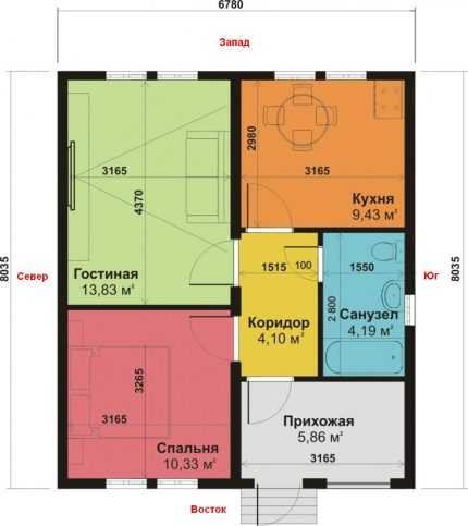
For calculations, it is most convenient to draw a house plan on paper, indicating on it the width, length, height of the building, the location of windows and doors, their dimensions
The walls of the building consist of:
- aerated concrete with a thickness of B = 0.21 m, thermal conductivity coefficient k = 2.87;
- foam B = 0.05 m, k = 1.678;
- facing brick В = 0.09 m, k = 2.26.
When determining k, information from tables should be used, or better - information from a technical passport, since the composition of materials from different manufacturers may differ, therefore, have different characteristics.
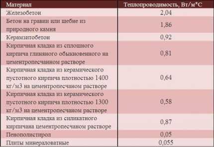
Reinforced concrete has the highest thermal conductivity, mineral wool slabs - the lowest, so they are most effectively used in the construction of warm houses
The floor of the house consists of the following layers:
- sand, B = 0.10 m, k = 0.58;
- crushed stone, B = 0.10 m, k = 0.13;
- concrete, B = 0.20 m, k = 1.1;
- ecowool insulation, B = 0.20 m, k = 0.043;
- reinforced screed, B = 0.30 m k = 0.93.
In the above plan of the house, the floor has the same structure throughout the entire area, there is no basement.
The ceiling consists of:
- mineral wool, B = 0.10 m, k = 0.05;
- drywall, B = 0.025 m, k = 0.21;
- pine shields, B = 0.05 m, k = 0.35.
The ceiling has no exits to the attic.
There are only 8 windows in the house, all of them are two-chambered with K-glass, argon, D = 0.6. Six windows have dimensions of 1.2x1.5 m, one is 1.2x2 m, and one is 0.3x0.5 m. The doors have dimensions of 1x2.2 m, the D index according to the passport is 0.36.
General provisions on the design of ventilation and air conditioning systems
Regardless of whether the design of heating-ventilation-air conditioning systems is carried out for a small mansion or a high-rise building, the result of the work performed should be 2 documents:
- text part - in the explanatory note, the designer indicates the general technical solutions adopted in the project... In particular, the calculation justifies the accepted cross-section of air ducts, the capacity of the air conditioning system and heating installations. If the system will be installed at an industrial enterprise, then it is necessary to indicate the methods of protecting the air ducts from aggressive media;
- graphic part - drawings should contain a diagram of heating, air conditioning and ventilation networks... In the case of combining ventilation and air heating, the work is slightly simplified.
Ventilation of the cottage floor
With regard to the drawings, it should be noted that they must be performed in strict accordance with GOST 21.602-79, a simple freehand sketch on graph paper is unacceptable.
Note! If you are designing ventilation and heating of a small house with your own hands, then, of course, you can do without GOST, the main thing is that the employees understand everything. In other cases, strict adherence to the standard is mandatory.
Drawing rules
The drawing should contain not only a schematic representation of the projected system itself, but also a plan of the house, otherwise it will be impossible to assess whether, for example, an air duct has been laid correctly.
As for the design of systems for multi-storey buildings, in general it is necessary:
- draw a floor plan of the building on sheet A1;
- number the premises, while the numbering is made in accordance with the requirements of GOST 21.602-2003, which was adopted to replace the still Soviet normative document GOST 21.602-79. As for the numbering of rooms, the number should be placed in a circle, the numbering is carried out starting from the left side of the drawing, while the first number is used to indicate the floor number, and all the rest are, in fact, the room numbers;
- then on the same plan it is imperative to apply the dimensions of the enclosing structures, this is the basis for the subsequent calculation of heat loss;
- if water heating is used, then a place is selected for placing the unit, on each floor the piping is indicated and the location of the radiators is indicated;
Note! GOST for working drawings for heating and ventilation gives a clear list of acceptable symbols. Creativity in this matter is unacceptable, and examples of some designations will be discussed below.
- the same applies to the display on duct sheets and room air conditioning systems.
Accepted conventions in the drawings
In the general case, the design of a ventilation system begins with the fact that their design position is indicated on the floors. After that, it is imperative to give cuts in all rooms where ventilation is provided.
On these sections, you need to show the design position of the vent gratings (indicate the height of their placement and dimensions), in addition, you need to display:
- ventilation ducts and a shaft (shown by a dotted line);
- the mark of the mouth of the ventilation shaft and the center of the window must be indicated;
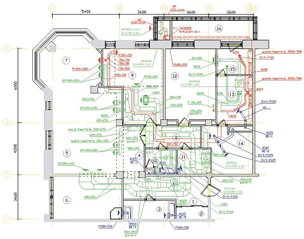
- the cuts and floor plans of the building made serve as the basis for drawing the axonometric projection of the ventilation system.

Axonometric projection of ventilation on the floor
Note! The same instructions apply to the design of air heating systems combined with the ventilation system of the premises.
When creating drawings, the following rules apply:
- any element of the ventilation and heating system must be marked and its serial number is affixed (within the same brand). For example, a supply system with natural circulation is denoted as PE, with a forced circulation - P, the air curtain in the drawing is denoted by the letter U, and heating units can be identified by the letter A.
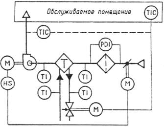
Technological diagram of the ventilation system
GOST execution of drawings heating and ventilation is not limited to one document of 2003 only.
The marking of some elements of ventilation and heating systems is given in separate regulations:
- when designating air ducts and fittings on a sheet, one should adhere to the recommendations of GOST 21.206-93;
- GOST 21.205-93 should be used when it is necessary to display in the drawing such an element as pipeline insulation, a shock-absorbing insert, a support and other specific elements. The same standard is used to indicate the direction of the air flow, tanks, pipeline fittings, etc.
Legend examples
- GOST 21.112-93 is devoted to the symbols of lifting and transport equipment.
Note! When displaying symbols of this type in the drawing, the scale must be taken into account.
General design guide
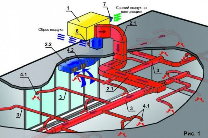
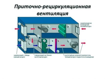
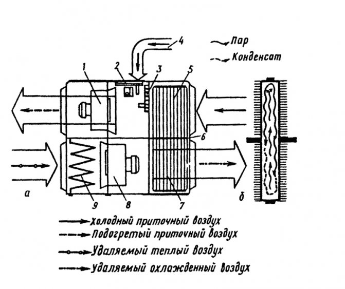
The ventilation system combined with the heating system works according to the following principle:
- warm air is supplied through the supply air duct to the rooms of the house;
- air from the premises is taken through the exhaust pipe, fresh air is added from the street, and the air mixture is fed back to the heating block;
- after that, the process is repeated.
Note! Such systems are necessarily equipped with a filter system; the function of additional humidification is often found. The circulating air needs additional cleaning, because it is not completely replaced by fresh air.
The filter is an obligatory element of every ventilation system
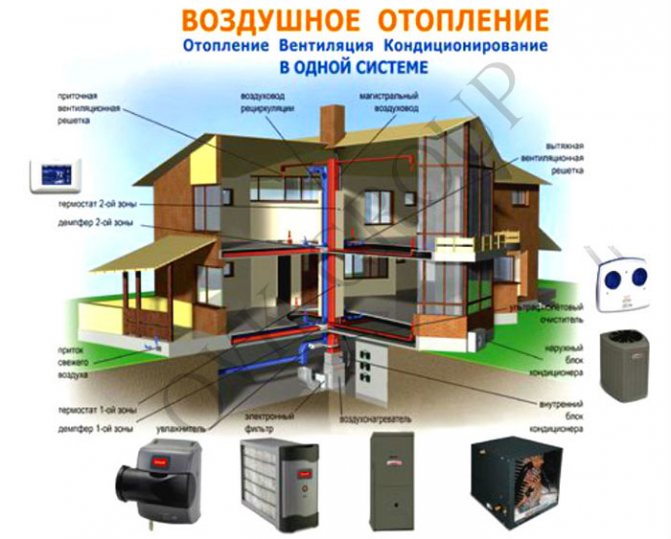
In private construction, in each case, the design of heating, ventilation and air conditioning is individual, but several universal rules can be formulated:
- the supply air duct can be conveniently placed between floors. This option is especially suitable for frame construction technology, the pipes will not take up a single centimeter of the free area of the room. With this arrangement, on the 2nd floor, warm air will come from the floor level, and on the 1st floor - from the ceiling;
Note! It should be borne in mind that warm air will come from the supply grilles, therefore it is undesirable to place them directly above the sofa, armchair, etc. At the same time, it is undesirable to place them above the curtains - hardly anyone will be pleased to look at the constantly swaying curtains.
- if the floors are reinforced concrete, then it is better to place the air ducts in the corners near the walls. Then they can be easily disguised using a multi-level ceiling.
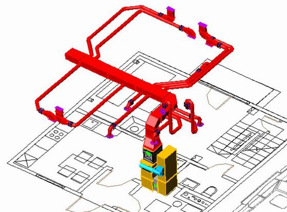
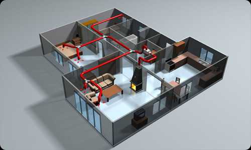
3D model of a duct supplying warm air
There are some peculiarities in relation to the placement of the return - exhaust duct.
Thus, the correct design of heating and ventilation systems requires that:
- the air got into the exhaust pipe on the lower floor - at the floor level. The fact is that here the heated air enters the premises from above, therefore, its intake from the floor contributes to a more uniform heating of the room;
Cooled air intake duct
- on the 2nd and subsequent floors, the fence should be made at the ceiling - warm air rises and accumulates in this zone, which does not play any role for a person;
- it is on this duct that it makes sense to place a damper to regulate the air flow, in winter this will help save on electricity bills;
- special attention should be paid to soundproofing the air ducts in the areas adjacent to the heating unit. Perhaps it makes sense to use flexible air ducts in these areas or apply external sound insulation;
- in the summer, the heating will not work, therefore, the exhaust ventilation must have a roof outlet; in the warm season, polluted air will be removed through it;
- fresh air from outside can be mixed through wall valves.

This is what the system looks like as a whole.
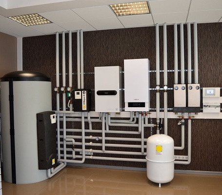
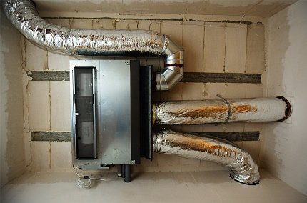
Separately, mention should be made of the heat source. Of course, you can use installations powered by electricity, but such systems can hardly be called economical, and for country houses, dependence on electricity is not the best option.
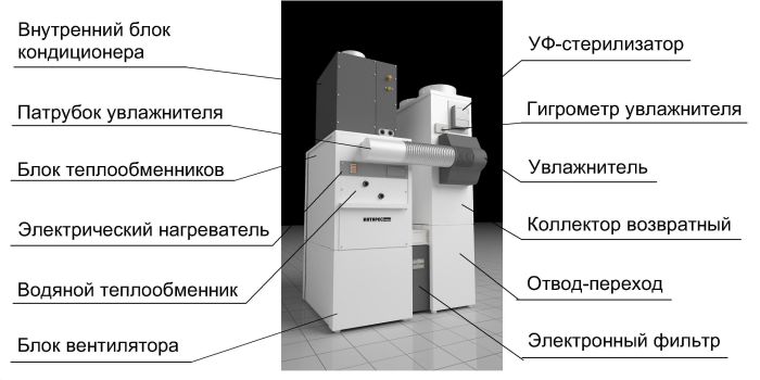
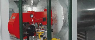
In the photo - ventilation unit
Therefore, installations are often used in which the heating element is connected to a conventional heating boiler (electric or solid fuel - it does not matter). The operating cost of such systems is about 20-30% lower in comparison with conventional water heating.
Note! In addition, the boiler can be simultaneously used for hot water supply and, for example, "warm floors".
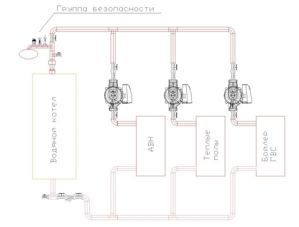
A water boiler is used not only for heating homes
Calculation of the number of ventilation grilles
The number of ventilation grilles and the air velocity in the duct are calculated:
1) We set the number of lattices and choose their sizes from the catalog
2) Knowing their number and air consumption, we calculate the amount of air for 1 grill
3) We calculate the speed of air exit from the air distributor according to the formula V = q / S, where q is the amount of air per grille, and S is the area of the air distributor. It is imperative that you familiarize yourself with the standard outflow rate, and only after the calculated speed is less than the standard one can it be considered that the number of gratings is selected correctly.
How to choose equipment
The choice of a specific device, unit or kit is made according to catalogs or tables. Today there are a large number of ready-made complexes with a certain power and heating source. From them, you can choose the most suitable option in terms of characteristics, price and other parameters, taken into account based on the operating conditions and purpose of the building.
The cost of air heating, the cost of its maintenance
The cost of the kit depends on the heating source. If a heat carrier from the central heating system is used, then to create air heating, you can get by with the purchase of a water heater and a fan. If the possibility of using network resources is not available, then the costs increase by the cost of the boiler. In addition, you will need to make the layout of the air ducts, provide supply and exhaust ventilation, recuperation, etc. The final price depends on the size of the building, the type of equipment, the manufacturer and other circumstances.
Maintenance costs air heating depend on the amount of electricity consumption by the fans and the amount of heat carrier circulating in the system. If you use your own boiler, then the price of fuel is added to the cost of electricity. The total amount of expenses depends on the time of year, the size of the house, the climatic conditions in the region, etc. In general, air heating is unambiguously recognized as the most economical option, high efficiency and the possibility of autonomous existence allow reducing heating costs to a minimum.
The economy and simplicity of the system make it easy to install with your own hands, high maintainability allows you to perform all the required operations on your own and in a short time. Given the availability and variety of primary heating sources, the air heating system can be called the most efficient and attractive for all types of premises.
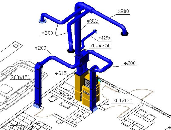
Aerodynamic system design
5. We do the aerodynamic calculation of the system. To facilitate the calculation, experts advise to approximately determine the cross-section of the main air duct for the total air consumption:
- flow rate 850 m3 / hour - size 200 x 400 mm
- Flow rate 1000 m3 / h - size 200 x 450 mm
- Flow rate 1 100 m3 / hour - size 200 x 500 mm
- Flow rate 1 200 m3 / hour - size 250 x 450 mm
- Flow rate 1 350 m3 / h - size 250 x 500 mm
- Flow rate 1 500 m3 / h - size 250 x 550 mm
- Flow rate 1 650 m3 / hour - size 300 x 500 mm
- Flow rate 1 800 m3 / h - size 300 x 550 mm
How to choose the right air ducts for air heating?
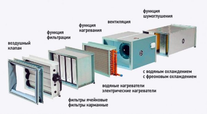
Additional equipment increasing the efficiency of air heating systems
For the reliable operation of this heating system, it is necessary to provide for the installation of a backup fan or to mount at least two heating units per room.
If the main fan fails, the room temperature may drop below normal, but not more than 5 degrees, provided the outside air is supplied.
The temperature of the air flow supplied to the premises must be at least twenty percent lower than the critical temperature of autoignition of gases and aerosols present in the building.
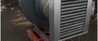
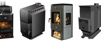
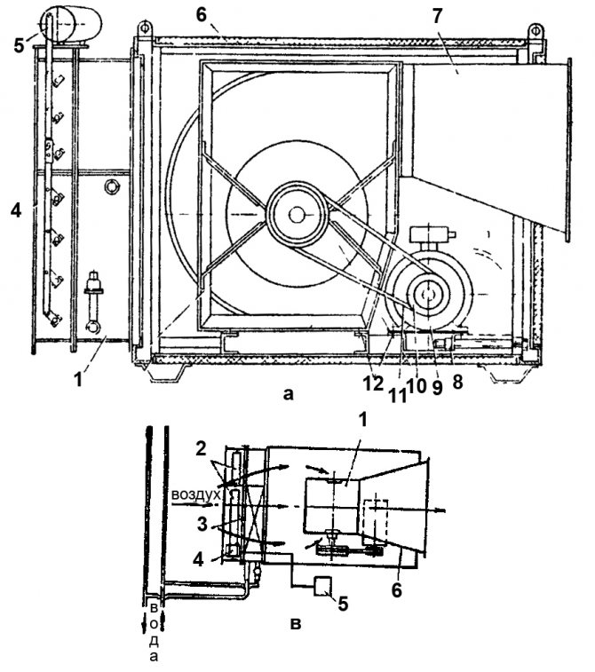
For heating the coolant in air heating systems, heating units of various types of structures are used.
They can also be used to complete heating units or ventilation supply chambers.
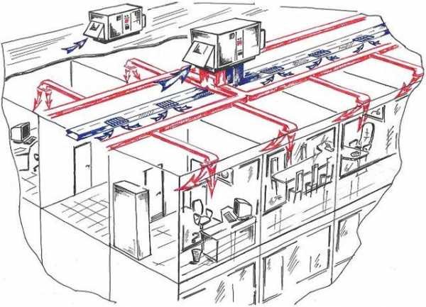
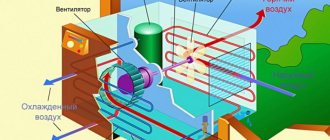
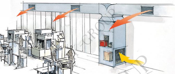
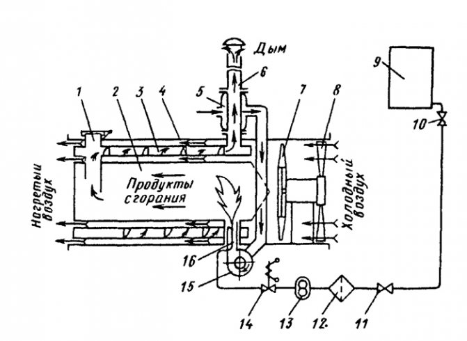
House air heating scheme. Click to enlarge.
In such heaters, air masses are heated by the energy taken from the coolant (steam, water or flue gases), and they can also be heated by electric power plants.
Heating units can be used to heat recirculated air.
They consist of a fan and a heater, as well as an apparatus that forms and directs the flow of the coolant supplied to the room.
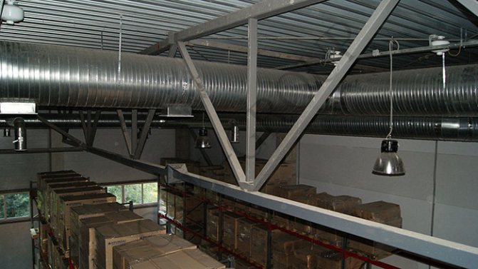
Large heating units are used to heat large production or industrial premises (for example, in wagon assembly shops), in which sanitary and hygienic and technological requirements allow the possibility of air recirculation.
Also, large heating air systems are used after hours for standby heating.
Classification of air heating systems
Such heating systems are divided according to the following criteria:
By type of energy carrier: systems with steam, water, gas or electric heaters.
By the nature of the flow of the heated coolant: mechanical (with the help of fans or blowers) and natural impulse.
By the type of ventilation schemes in heated rooms: direct-flow, or with partial or full recirculation.
By determining the place of heating the coolant: local (the air mass is heated by local heating units) and central (heating is carried out in a common centralized unit and subsequently transported to the heated buildings and premises).