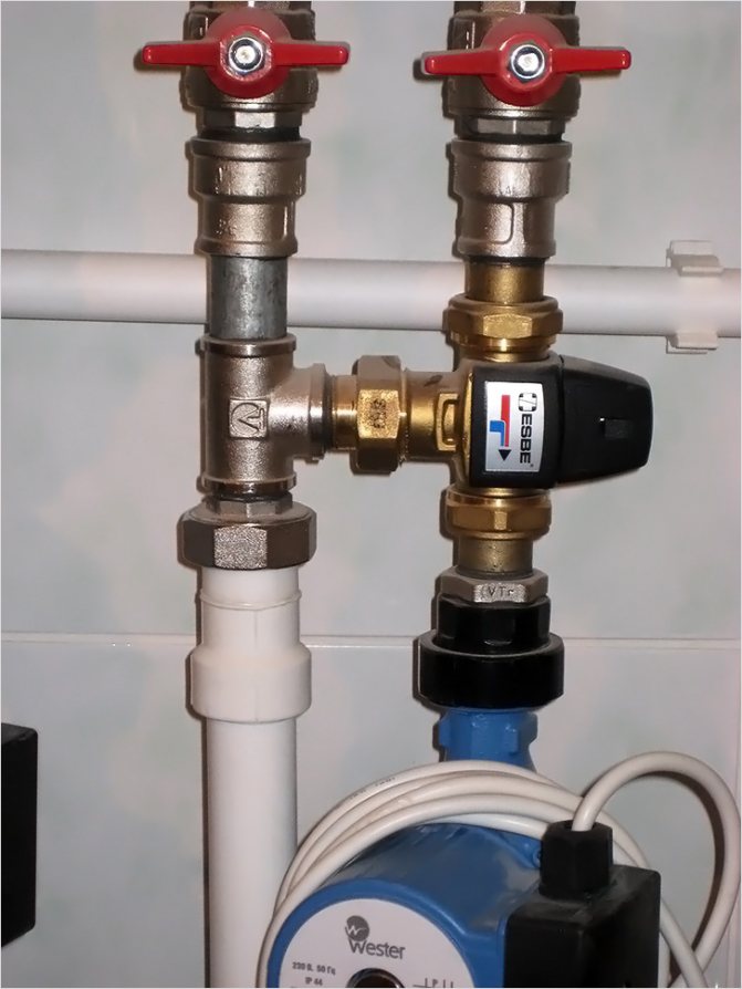
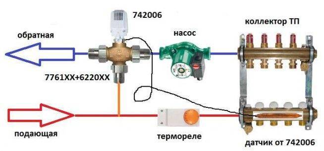
Connection via 3-way valve
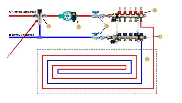
A slightly different assembly and principle of operation is the option of connecting a heated floor through a three-way valve, which is shown in the diagram below with an arrow.
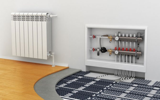
This scheme is used in cases where, in addition to the warm floor, the system also contains a main heating circuit. The temperatures of the coolant in them will be different, which is why a mixing valve is needed.
Connection via 3-way valve
- This device not only regulates the supply of water to the circuit (mounted on the supply pipe in front of the circulation pump), but at the same time, using a built-in thermostat, controls its temperature, mixing the cold heat carrier with the hot one. In this case, the pressure in the pipeline corresponds to the pressure set at the pump.
- However, the valve cannot accurately meter the amount of water for mixing, therefore the temperature in the floor circuit may be either subcooled or too hot. The problem is solved by connecting a servo to it, since it is he who balances the operation of the system and protects the floors from overheating.
Three-way mixing valve
A circuit with a mixing valve is quite accessible for self-assembly, and the equipment for it does not require large costs.
Wiring diagram for underfloor heating from a heating radiator
Sometimes, instead of the "boiler - mixing and collector unit - circuits" scheme, other options for connecting a warm floor are used. And the most common of them is the connection of the ECP circuit to the heating radiator.
The diagram looks like this:
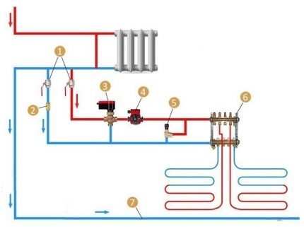
Connection is carried out to the return pipe: 1 - shut-off ball valves; 2 - check valve; 3 - three-way mixing unit; 4 - circulation pump; 5 - air valve; 6 - collector unit; 7 - pipe to the boiler
The disadvantage of the scheme is the seasonal use of a warm floor. As you know, heating radiators are not used in summer, therefore, the floor will also remain cold.
So that the temperature of the coolant does not rise above normal, a special sensor with a valve is included in the circuit. It automatically shuts off the flow of water as soon as it becomes excessively hot. When the coolant has cooled down to an acceptable temperature, the thermal valve opens again.
This type of ECP can be organized without a pumping and mixing unit. The only adjustment tool is a thermostatic device mounted on the supply pipe.
Two-way valve circuit
Install it on the supply from a heating device. In the place of the jumper between the supply pipeline and the return line, a balancing adjustable valve is mounted. It is adjusted in accordance with the required temperature of the supplied water, usually using a hex key. It is needed to adjust the amount of cold coolant.
The temperature sensor is placed after the pump, which in turn moves the water in the direction of the comb. Only now the intensity of movement of the heated coolant from the boiler changes. Thus, the temperature of the supplied water changes at the inlet of the pump, while the cold flow is adjusted and stable.
Mixing always takes place and water from the boiler does not directly enter the circuits, since this is impossible. This scheme can be considered more reliable. But it should be noted that the mixing group, equipped with a two-way element, is capable of heating 150-200 "squares" of the area, since there are no valves of greater capacity.
Collector for underfloor heating system
For underfloor heating, a common collector unit is most often mounted, or a separate collector is installed in front of each heating circuit. If the latter option is implemented, then all collectors are equipped with flow meters, thermostats, and the following elements:
- Return and supply mixing valve;
- Heater balancing shut-off valve;
- Overflow valve.
It is possible to assemble a collector for a warm floor yourself according to different schemes, and in some schemes of collector nodes bypasses are used, but not always - only in single-circuit systems. If the underfloor heating system is organized according to a two-circuit scheme, then the collector can be connected without a bypass to the secondary circuit.

Double-circuit underfloor heating system with a collector
Before assembling a manifold assembly for a warm floor, weigh your possibilities - sometimes it is easier to buy a ready-made structure. If the collector is to be bought, it is better that all its parts and elements are from the same manufacturer. When assembling the unit yourself, you must choose the material from which the main components of the unit will be assembled: from copper, steel, polymers or brass.
Also, when choosing an industrial design, it is important to consider the following parameters:
- How many heating circuits will be in the system (usually from 2 to 12), the total length of the pipeline and the throughput of the circuits;
- Maximum allowable pressure in pipes;
- The possibility of expanding the heating system;
- Manual or automatic control of the collector;
- Electric power of all units and assemblies;
- The diameter of the internal openings of the collector (throughput).
DIY collector
The most efficient operation of the assembled manifold assemblies can be ensured by connecting to them heating circuits of the same length. In order to equalize the pipelines in length with sufficient accuracy, they are divided into equal segments, which are connected to the collector. The easiest way to calculate the collector unit is in a special computer program or on an online calculator so that a phenomenon called "heat zebra" does not appear, that is, uneven heating of the floor.
For the calculation, you need the following data:
- Type of decorative flooring;
- the area of the heated room and the plan for placing large items in it;
- Material and diameter of the circuit pipes;
- Boiler rated power;
- Floor insulation type.
Reservoir calculation
Collector installation - recommendations
When designing a floor heating system, you first need to find the optimal place for installing the collector. As a standard, the unit is installed in a manifold cabinet, and the cabinet itself is mounted at a height of 30-40 cm from the floor level next to the supply and return.
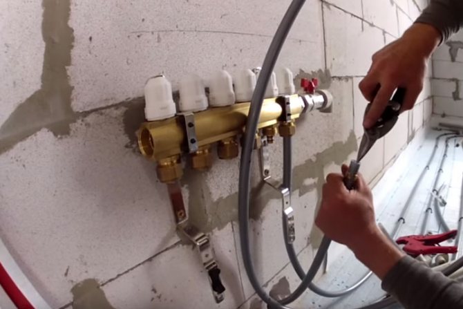
In order not to blame your own mistakes and ensure maximum heating of the underfloor heating pipes, study the instructions for connecting the collector. Then assemble the assembly in the following sequence (this applies to the industrial manifold assembly):
- Unpack the pipes for direct and return flow of the heating medium. The pipes must be with flow meters and supply valves. If the manifold is multi-section, assemble the sections into one structure;
- From the assembled sections, you need to assemble a unit on brackets (included);
- Next, we install shut-off valves, automation, sensors and the rest of the connecting fittings;
- We attach the unit to the wall or in the cabinet, mount the thermostat, servo drive and circulation pump;
- We connect pipes from the boiler and pipes from the heating circuits of the "warm floor" system.
Collector set
Now the connection diagram of the underfloor heating collector is pressurized, after which the concrete screed can be poured. The thermal settings of the collector can be carried out after the installation of the topcoat.
Do-it-yourself manifold assembly
A factory collector is a rather expensive product, so many craftsmen want to make it with their own hands.Many items will still have to be purchased, but the cost will be cheaper. The easiest way is to solder a self-made collector from PVC pipes and fittings Ø 25-32 mm. You will also need tees and bends of the same diameters, and shut-off valves.
Homemade collector
The number of valves and fittings is calculated according to the number of heating circuits. Of the tools, you need a soldering iron for propylene elements and nozzles for it, special scissors for cutting pipes and a tape measure.
The marking of the collector consists in marking and cutting off the pipes of the required length, observing the minimum distance between the tees. Valves and transitions are soldered to PVC tees with a soldering iron. Fittings for connecting the pump are soldered to this structure. As you can see, everything is simple, but it is better to buy more complex manifold units ready-made.
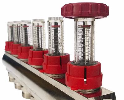
How to install the flow meter correctly
According to the manufacturer's recommendation, the flowmeter is mounted on the collector return, although installation on the supply is possible.
The main requirement for installing a variable area flowmeter is vertical placement. This position will allow you to correctly calculate the water level. Therefore, the comb must be positioned strictly horizontally. The accuracy of the installation can be determined using a plumb line or level.
Comb for underfloor heating: installation and adjustment, do-it-yourself manufacturing, step-by-step instructions with photos and videos.
Since the device - a collector plus a rotameter, should work automatically, an additional connection of a temperature sensor is required. Such a scheme completely or partially blocks the flow of the coolant to the loops when the required degree of heating is reached.
Do-it-yourself collector installation: connection diagram and configuration, types and principle of operation.
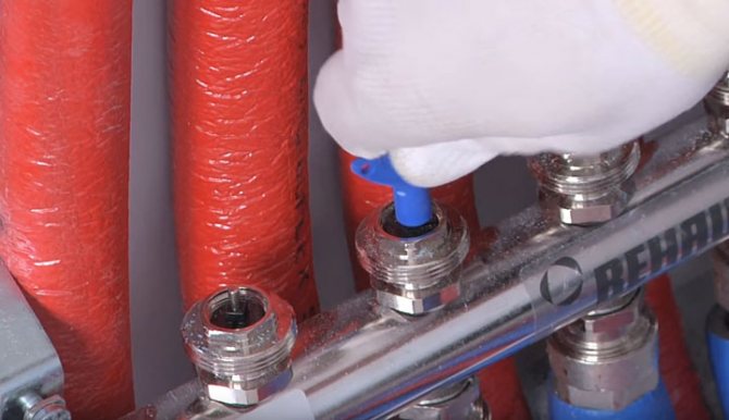
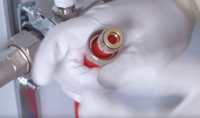
The process of installing the flow meter itself is as follows:
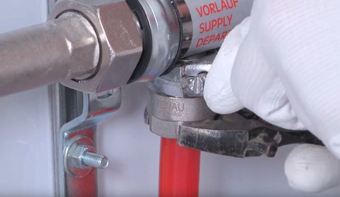
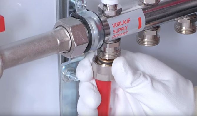
- A rotameter is installed - this is done by screwing it into the socket of the collecting comb of the collector with a special key, the position is strictly vertical. The device is equipped with an O-ring and a nut.
For your information! This connection does not need additional insulation.
- The flask is twisted and removed - by turning it counterclockwise. Then the ring is removed, which is intended for protection by the manufacturer. After that, the flask with marks is put on in the reverse order.
- The brass ring is turned clockwise to the required value, thereby balancing the speed of the incoming heat carrier.
- The brass ring is covered with an overlay - this will prevent the device from mechanical damage.
After these steps, it is imperative to check the entire system for operability.
Adjustment of the underfloor heating collector with flow meters and its correction
Having convinced of the functioning of the structure, many people have a question - how to properly regulate the warm floor with flow meters? The process is simple, because the use of rotameters greatly facilitates the procedure.
With manual adjustment, the work is quite time consuming, since the adjustment is carried out using a conventional tap - a thermal head, which is installed on the return and supply.
This method significantly reduces the cost of installing the structure, but such an adjustment will take a lot of time. In addition, the accuracy of adjustment during manual balancing suffers, because the temperature will have to be determined based on personal feelings.
The most convenient method is considered to be carrying out adjustment work with flow meters installed at the inlet to the coil. A separate adjustment should be made in each room, taking into account the level of heating of the liquid and the hydraulic resistance.
All that will need to be done later is to control the difference in indicators between the circuits, they should not exceed 0.3 - 0.5 liters.
Before adjusting the underfloor heating on the manifold with flow meters, you need to understand why you need it. The task of balancing is to establish the demand of each branch and the overall balance of costs.
In addition, the correct setting of the flow meters on the manifold affects the quality of the floor covering during operation - after all, it should not overheat. Higher temperatures will damage the floor unit and will need to be replaced.
The operating principle of underfloor heating is different from other heating devices. The peculiarity lies in the difference in water temperatures, if a liquid heated to 80 degrees circulates in the radiators, then 40 degrees in a warm floor, while the surface heats up to 22 degrees.
For your information! There is an opinion that a warm floor system does not need balancing, and the water flow in the loops is regulated independently, using automatic devices - thermostats and controllers, but this is a wrong reasoning.
Regulatory process
As mentioned above, it is necessary to carry out a separate adjustment of each circuit, taking into account the laying of the pipeline. After all, the volume of the coolant for each coil requires a different, and depends on its length.
This indicator is determined by the formula - the heat load is taken in relation to the heat capacity of the water, and to the temperature difference at the inlet and outlet. Before the procedure, it is necessary to check the installed circuit for leaks, since they will distort the indicators during adjustment.
For this, the pipeline should be filled with water and vented, that is, open the flow meters, a three-way valve, an air vent, and shut-off valves on the supply and return.
This procedure is accompanied by a hissing sound, when it stops, this indicates a complete release of air. After that, all valves are closed except for one at the supply, and each circuit is pressurized in turn.
Then, you can proceed to the regulation of underfloor heating flow meters, the procedure is as follows:
- The size of the coolant that passes through the collector group in 1 minute is calculated. This indicator is measured in liters, the resulting value is taken as 100%.
- The water demand for each water circuit is determined separately, in percent. The result should then be converted to liters per minute. It is necessary to start with the longest loop, and at the highest power, by opening the control valve to full power.
For your information! Further, the flow rate in other coils will be set relative to it.
- The volume of water supplied to the line is corrected by flow meters.
After the flow meters are configured, the circulation pump on the distribution unit is turned on. Hot water will begin to flow into the pipeline, which will displace cold water, this procedure will take 3 hours.
For your information! Before starting the floor into operation, the maximum indicators should be set on the flow meters, usually they are different for each branch, subsequently they must be adjusted so that the heating is uniform.
It should be said that the process of adjusting a system with a rotameter depends on its model. If the meter does not have a built-in valve, then an additional shut-off element is required to assist in setting the "open" position. In this case, the balancing process takes place with a functioning device.
If a combined type of device is available, it is recommended to carry out a preliminary adjustment by turning the built-in valve to full power.
How to clean a flow meter
The flow meter, like any device, needs periodic maintenance, or rather, cleaning. The process is simple, and you can do the work yourself:
- The valve is closed by turning the cap clockwise.
- The flask is removed and cleaned, after which it is put in place.Cleaning consists in wiping it from the inside with a soft cloth or in rinsing with water and detergent.
- Then the valve is opened by turning it counterclockwise.
For your information! When dismantling the flask, there is no need to relieve pressure in the system, since the valves will prevent leaks.
Not infrequently, when the collector group is operating, the flow meter pointer sticks. To restore its function, it is necessary to force the shut-off valve to open.
If, during the operation of the device, the flask is cracked, then it is better to twist it and replace it with a new one, since the crack can interfere with the determination of the volume of the coolant.
For the efficient operation of a warm water floor, it is required not only to choose the right model of the flow meter, but also to make competent installation and adjustment. If you are not confident in your abilities, then it is better to invite professionals.
Controlling the operation of the underfloor heating system
The efficiency of heating devices depends not only on their power and adjustments, but, first of all, on the state of the heated object. If the building is not sufficiently insulated, no system will create conditions for a comfortable life in it. Walls made of porous materials, such as sawn shell rock or foam concrete, reduce heat loss by 20 - 25% compared to ceramic bricks, additional wall insulation and wind protection, as well as insulation of the roofing cake, give approximately the same effect.
Turning to the issue of controlling the operating mode of underfloor heating, it should be noted that two main approaches are used: manual control of the mixing unit and the use of automatic control systems.
The first option is used for small buildings, consisting of 2 or 3 living rooms and auxiliary premises. The mixing mode is set manually with an ordinary crane.
For complex developed heating networks, this method is unrealistic due to the multifactorial nature of the process and complex automated devices are used.
Heating control systems can be:
- group - their task is to convert the temperature of the water leaving the boiler at 75 - 90 degrees to 35 - 40 degrees at the inlet required for low-temperature circuits and control the return flow temperature by making adjustments to the mixing mode. Naturally, changes in weather conditions also affect the amount of heat transfer in the heating system;
- individual - the flow rate of the heat carrier for each circuit is set in such a way that the room has a constant temperature in the specified interval. This is achieved either by installing a room temperature sensor or by monitoring the return flow temperature downstream of the register directly at the manifold assembly.
Equipment
Within the framework of a small article, it is impossible to display all the variety of devices, so let's dwell on some of their typical representatives:
Group controllers
Heating is controlled by applying an impulse to the control valve servo, which performs the appropriate manipulation. In one controller, up to 10 channels from sensors are installed to adjust the mix in various circuits. Programming of work is possible.
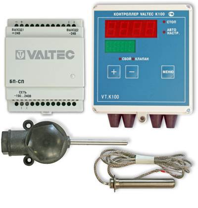
Underfloor heating operating mode control unit
When an external temperature sensor is connected, the heating medium heating temperature mode changes preventively.
Thermostats
A remote device capable of measuring the temperature at the installation site and transmitting data about it to the heating system control unit. The device can transmit information both by wire and by radio. It should be installed in a place protected from sunlight and away from drafts.
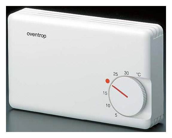
Room thermostat for water floor
A device for direct control of the temperature of the heat carrier flow. P is located in the rupture of the pipeline.Usually equipped with a servo motor to control the damper. Calculated at work at a pressure in the system up to 16 atmospheres.
Three-way thermostatic valve in the underfloor heating system
Servo
A device that drives a valve shut-off device (stem). The device is small in size and generates a force of more than 10 kg.
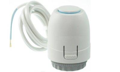
Servo for underfloor heating valve
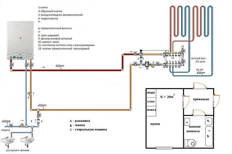
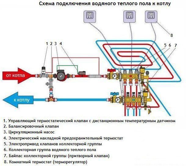
Direct connection diagram
You have a boiler, after which all safety fittings + circulation pump are installed. In some wall-mounted versions of boilers, the pump is initially built into its body.
For floor-standing copies, you will have to install it separately. From this boiler, water is first directed to the distribution manifold, and then scatters along the loops. After that, having completed the passage, it returns through the return to the heat generator.
With such a scheme, the boiler is directly adjusted to the desired temperature of the TPs themselves. You don't have any additional heaters or radiators here.
What are the main features worth paying attention to here? First, with such a direct connection, it is advisable to install a condensing boiler. In such circuits, operation at relatively low temperatures for the condenser is quite optimal.
In this mode, it will reach its highest efficiency
In such circuits, operation at relatively low temperatures for the condenser is quite optimal. In this mode, it will reach its highest efficiency.
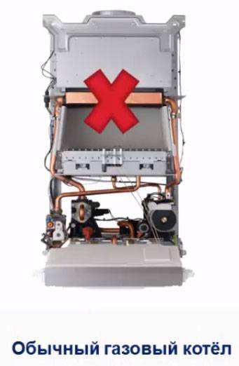
If you use an ordinary gas boiler, you will soon say goodbye to your heat exchanger.
The second nuance concerns solid fuel boilers. When you have it installed, for direct connection to underfloor heating, you also need a buffer tank.
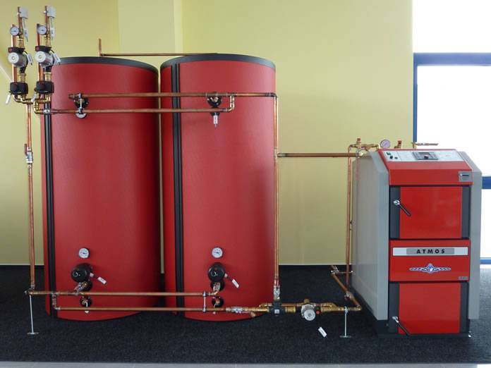
It is needed to limit the temperature regime. It is very difficult to regulate the temperature directly with solid fuel boilers.
Contour balancing and screed filling
Further, there is a hydraulic balancing of individual contours of the warm floor. To do this, use a special adjusting key to set the value set by the designer on the fine adjustment valves.
If you do not have such valves, then set the estimated flow rate of the coolant for each heating circuit. This is done by flow meters.
They set a duct in order to align all the contours with each other. After all, the length of each can be any, and your coolant must pass evenly along all the contours, and not only along the shortest one.

After pressure testing and testing for leaks, the pipes are filled with a tie. In this case, the system must be filled with cold water and under pressure.
Mistake # 6 - fill the screed with empty pipes.
When the screed has gained strength, a thermal test is carried out. This takes 7 days.
Moreover, during the first three days, the heating system is flushed with water at a temperature of 20 degrees. In the next 4 days, the maximum operating temperature is set and the heating of all circuits is checked.
The thermal test is also documented in a protocol.
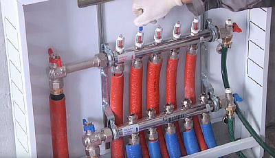
How to assemble and connect the manifold correctly
Install the frame - the collector is mounted horizontally directly on the wall, or in a cut-out niche. The only condition for installation is free access to the arrow of the heating pipes. It is also possible to install a collector cabinet with your own hands.
The cabinet will allow you to hide the wiring from prying eyes, which is especially important if a bathroom or hallway is used under the boiler room.
Connection to the boiler - the coolant is supplied from the bottom, the return flow goes from the top. Ball cutoffs must be installed in front of the frame.
A pumping group is installed immediately behind the cranes.To maintain the required temperature, the heated heat carrier is used only partially. The pump not only creates the necessary pressure in the heating system, but also helps to mix the cooled water from the floor circuit and heated water from the boiler. A check valve with a temperature limiter is installed. A distributor manifold is installed behind the valve. The wiring of the collector for underfloor heating is performed as follows. Pipes going to the warm floor are attached from above, from the heating system from below. If you need to assemble a distribution manifold of a warm water floor with your own hands, stopcocks with a built-in thermostat are installed in the comb. Practice shows that the best option is to purchase a ready-made structure. Assembling the manifold even by a professional and self-adjusting the valves is a laborious process that requires certain skills and experience. Connecting a warm water floor collector requires the use of special accessories. Compression fittings are used, consisting of a support sleeve, a clamping ring and an intermediate brass nut. After installation, the collector is set up.
Pressure testing of the manifold - after completion of the installation work, it is necessary to check the sealing of the connections. For this, the completed collector group is connected to a pump (pressure operator). With the help of a pressure operator, pressure is built up in the system. The water circuit is left under pressure for a day. If the pressure indicators have not changed, it means that the installation of the underfloor heating collector with your own hands was done correctly and the mixing unit is ready for operation.
At first glance, assembling a collector with your own hands seems quite simple. But as practice shows, it is better not to start installation without the necessary tools and special skills.
How to choose equipment?
Thermostatic devices are selected depending on the throughput of the coolant. It must correspond to the volume of liquid that is pumped into the heating system. The data is indicated in the technical data sheet for the boiler.
For hot and cold circuits, metal pipes with a diameter of 26 * 2 mm are used. The nozzles of a three-way mixer should have the same diameter. Otherwise, you will have to install adapters, which is not desirable for the heating system. The seams are heavily loaded. You must always monitor their tightness.
We recommend: Is it possible to lay laminate flooring on a warm floor?
The temperature of the liquid in the floor line is 55-35 ° C. The equipment is chosen depending on a certain thermal regime, which can be set on the thermostat. Radiator heating requires a wider temperature range, up to 80 ° C.
Thermostatic equipment is used to control the temperature regime in the room with water floor heating. Automation will facilitate the operation of the heating system, provide a normal microclimate in individual rooms of the cottage, and save electricity.
When using the device with software, it becomes possible to regulate the temperature of the floor line depending on the time of day, days of the week.
YouTube responded with an error: Access Not Configured. YouTube Data API has not been used in project 268921522881 before or it is disabled. Enable it by visiting https://console.developers.google.com/apis/api/youtube.googleapis.com/overview?project=268921522881 then retry. If you enabled this API recently, wait a few minutes for the action to propagate to our systems and retry.
- Similar posts
- How to put underfloor heating under PVC?
- How to assemble a collector for a warm floor?
- How is the underfloor heating sensor installed?
- How to install a warm floor in a garage?
- How to install underfloor heating under porcelain stoneware?
- How to put underfloor heating in the toilet?
Do you need a collector
The main disadvantage of the device is considered its high cost, but it must be taken into account that without it, warm water-type coatings will not be able to function normally. This is only possible if the cover consists of one heating circuit. In modern underfloor heating, the length of pipes for laying cannot exceed 70 meters.Since this amount will only be enough for 7 square meters of area, for a medium-sized room you will need at least three contours.
Most often, warm water-type coatings are installed in all rooms of an apartment or house. In this case, a mandatory installation of the collector will be required to evenly distribute the supply of the heat carrier. If we are talking about one small room, the collector may not be purchased. It must be remembered that without this device, the coolant will be supplied with the temperature as in the general heating system. Also, without it, it is impossible to remove air locks and control pressure.
Reason 1. Lack of thermal insulation
The most common reason why a warm floor does not cope with the functions assigned to it is that you simply forgot to install the thermal insulation properly, or did not install it at all. Often, a conventional polyethylene foam backing is used as thermal insulation. And the substrate is simply not intended for thermal insulation of warm floors. Instead, you need to use polystyrene foam with a thickness of 5-10 cm.
How to fix it?
Consider one thing. You will have to overpay for a warm floor. But it is possible that the situation will be corrected by a higher temperature supply to the warm floor and the use of more powerful heating equipment. But don't overdo it. The maximum temperature should not exceed 70 degrees. And it shouldn't be permanent. Otherwise, the pipe will quickly become unusable.
Collector connection to the boiler
The process of connecting a warm water floor with a comb is very simple and boils down to connecting the pipes of the heating circuits to the collector, and the collector itself to the boiler. However, there are differences in the configuration of the collector. This is what we will consider in this subsection.
The collector must be installed in such a way that it is convenient to lead the heating circuit pipes to it. So, install shut-off valves on the manifold. Connect the side outlet to the pipe both for supply and return.
If you buy a ready-made manifold kit, then it will already have all the necessary valves, even at the outlets of the pipes going to the boiler. The presence of taps will allow you, if necessary, to carry out repairs or temporarily disable one of the circuits. If you assemble the manifold yourself, then the assembly of the connection of each element is performed with a compression fitting. As a result, underfloor heating will be connected to the boiler through the collector.
To automate the control of the coolant temperature, the following set of equipment is additionally installed in the collector:
- Pump and mixing unit, which includes a three-way mixing valve.
- For forced circulation pump.
- Drain cock.
- Air vent.
So, instead of shut-off valves on the manifold, install thermostatic control valves. In their design, there is a thermal balloon with paraffin, which, pushing off from the air temperature in the room, narrows or expands. These actions set the capacity of the thermostatic valve. As for the pumping and mixing unit, the principle of its operation was described above.
So, we examined the basic and working schemes for connecting a warm water floor. As you can see, it is not enough to know how to properly install a water floor. It should be connected correctly. We hope this article will help you understand the intricacies of this work. And if you already have personal experience, then leave reviews and comments at the end of this article regarding the water heating floor connection schemes you use.
Collector circuit for connecting a warm floor
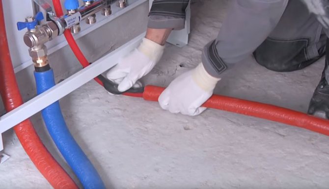
The whole process of self-connecting the floor to the boiler comes down to the fact that it is necessary to connect the pipes to the collectors, and connect the collectors themselves to the pipes that come from the boiler.As already mentioned, before connecting the warm floor to the heated equipment, the collector cabinet must be installed and the floor itself must be laid.
The manifold cabinet must be located in such a place that the supply and return pipes can easily enter it. It is necessary to connect the lateral outlets of the collector to the pipes for "return" (return) and supply.
However, before this, shut-off valves (shut-off valves) must be installed on the manifolds. The shut-off valve may include a thermometer for more convenient temperature control.
It is advisable to purchase a ready-made manifold set from a well-known manufacturer, which includes shut-off valves not only at the return and supply outlets, but also at all outlets for the installation of heat transfer pipes of the heated coating. This will make it possible to turn off 1 separate circuit of the entire system for repair, so that the rest will continue to work at this time.
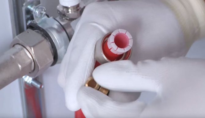
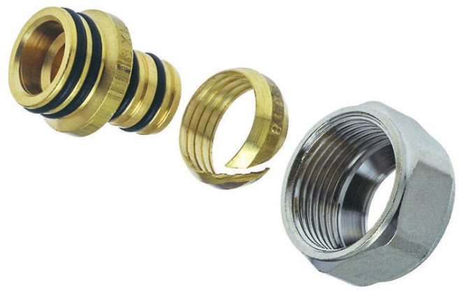
Pipes, taps, manifolds are connected to each other using compression fittings. The connection of the underfloor heating pipes to the collectors can be done using special connectors. The connector includes a clamping ring, support sleeve and brass nut. In the case of connecting different diameters, adapter fittings are used.
The simplest design option will consist of simple manifolds with shut-off valves. The connection of the return and supply with pipes and shut-off valves is made, the collectors and heat transfer pipes of the water coating are connected. This completes the installation of the floor heating system for the boiler.
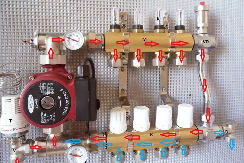
System elements
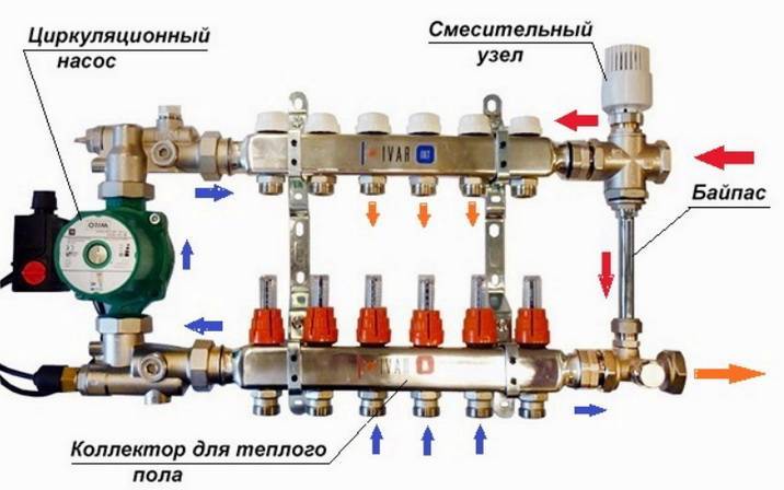
System elements
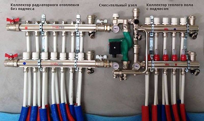
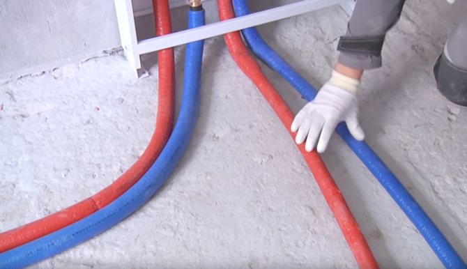
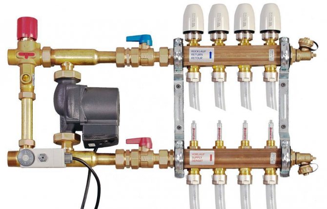
All schemes are united by ease of operation, the possibility of self-assembly, as well as the location of the main elements. The supply and return are located on the left side, and the manifold with combs - on the right. The differences between the schemes are in the addition of some details. Most often, the collector is located near the mixing unit, less often - at a distance, which may be due to a lack of free space or planning features of the room.
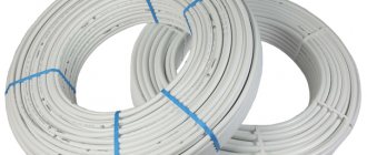
The composition of the components depends on the material of the pipes used - from cross-linked polypropylene, metal-plastic, corrugated stainless steel or copper.
The following elements are used in the scheme:
- Shut-off valves in the form of ball valves. They do not participate in adjusting the main indicators of the coolant - its temperature and pressure, but are necessary when carrying out repair work when it is required to turn off individual components of the system.
- An oblique filter designed for mechanical water purification. It is used in the system if there is no certainty about the purity of the water used. This filter keeps solids out of the tuner, thus ensuring correct system operation and extending valve life.
- Thermometers that provide visual control over the temperature of the water inside the circuit. Some models are equipped with a probe that comes into direct contact with the coolant. Thermometers are available in liquid, mechanical and digital.
- The thermostatic valve is the main control element of the mixing unit. A thermostatic head is put on top of it. When the temperature of the coolant changes, the head mechanically acts on the thermal valve. If the degree is exceeded, the valve closes, and when the temperature drops, it opens.
- A bypass for cold water withdrawal is a jumper, which is formed between the supply and return pipes with the help of sanitary tees. To accurately adjust the pressure of the coolant, a balancing valve is installed on the bypass, which will ensure the optimal operation of the system and its noiselessness.
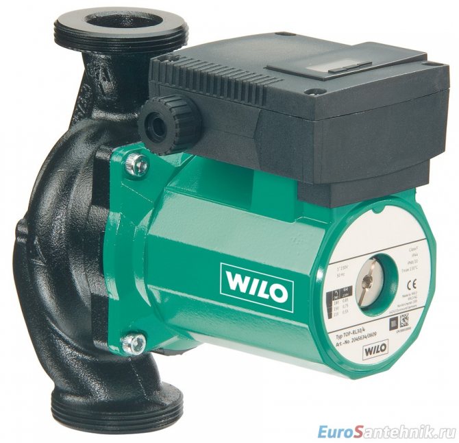
- The optimal speed of movement of water through the pipes is ensured by means of a circulation pump.
Supply choke
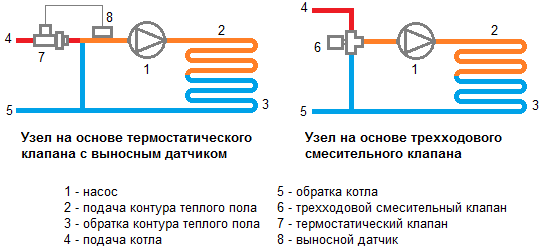
The two-way valve system is the simplest to implement. Control over the temperature of the water entering the pipes of the system is carried out thanks to a thermostatic head installed on the valve and a liquid sensor. The opening and closing of the valve is due to the head that passes hot water from the boiler into the circuit or cuts it off.
Thus, water from the "return" is supplied unlimitedly, and hot water only if necessary under the control of the valve. Due to this, overheating of the warm floor is excluded and its service life is extended. The low flow capacity of the two-way valve ensures smooth regulation of the water temperature, eliminating sudden changes.
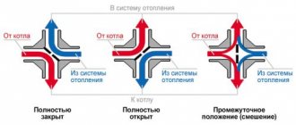
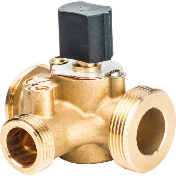
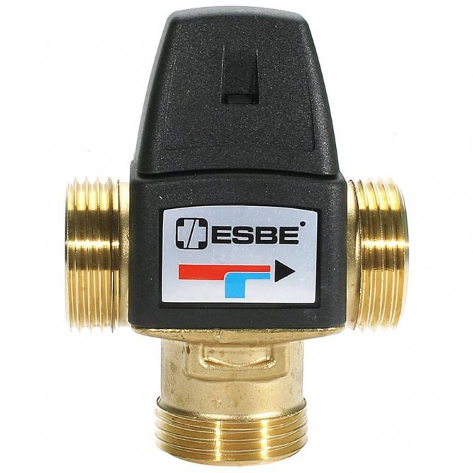
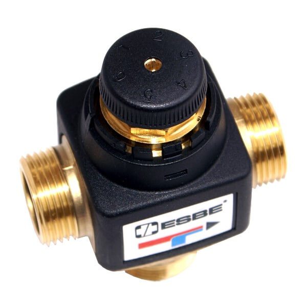
Three-way choke
Unlike a two-way valve, a three-way valve mixes water of different temperatures inside itself. This element combines a supply bypass valve and a bypass. The peculiarity lies in the possibility of adjusting the amount of hot and cold heat carrier for mixing, thanks to a damper located between the hot water pipe and the "return".
Such valves have disadvantages. There is a possibility of very hot water being supplied by a signal from a temperature sensor, which, due to a sharp drop, can provoke an increase in pressure in the pipes and a violation of the integrity of the circuits. The large flow capacity of the three-way valve can cause a sharp drop in the temperature of the water in the circuit, even with a minimal displacement of the device control.
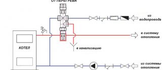
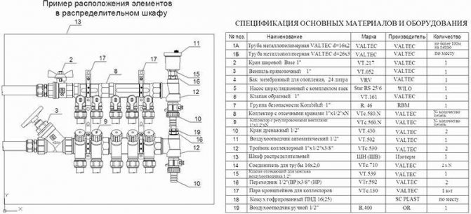
Installation features
The three-way valve is most often included in the mixing group, which, in addition to the valve, includes:
- check valve;
- circulating pump;
- temperature sensor.
According to this scheme, the installation is carried out in the following order:
- a pump is installed on the supply, which pumps hot water heated by the boiler;
- after it comes a temperature sensor that determines the level of heating of the coolant;
- then a three-way valve is mounted, which mixes the streams to a predetermined temperature.
- on the return loop, a valve with an outlet is fixed and connected to the cooled heat carrier entering the three-way mixing valve.
As a result, a heat carrier with a temperature regime necessary for uniform and efficient heating enters the pipeline of a water-heated floor.
If it is planned to install a floor heating system in small rooms, then the installation of a three-way valve is carried out without a mixing unit. The installation sequence of the mixing device in such a scheme is somewhat different:
- a three-way valve is attached to the hot liquid supply from the boiler;
- after it, a temperature sensor is installed;
- then a circulation pump is installed that delivers water at a regulated temperature to the underfloor heating circuit.
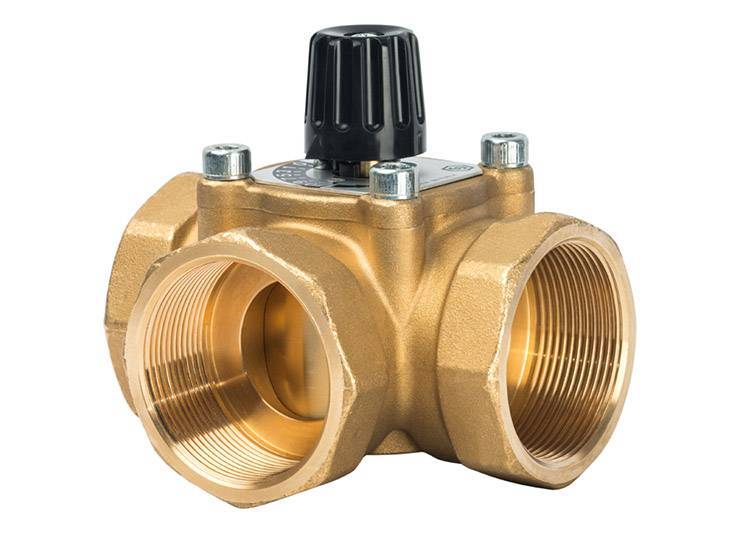
Three-way valves can have different hole patterns. The design features of the product depend on the direction of the coolant. Accordingly, there are two main mixing valve models:
- L-shaped. The device has two side openings and one circular opening at the bottom of the housing. During the operation of the system, the hot coolant enters from the side and mixes with the cooled liquid supplied from the bottom. The water of the required temperature goes into the circuit through the second side opening.
- T-shaped. According to this scheme, hot and cold coolant enters the valve through the holes located on the sides of the body. After mixing the hot and cold streams, the liquid enters the underfloor heating pipeline through the central outlet.
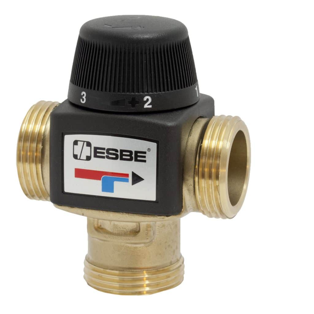
Three-way valve for underfloor heating T-shaped
During the operation of the heating system, a liquid heated to 80 degrees is supplied to the three-way valve.After mixing, the water circuit is filled with a coolant with temperatures optimal for a warm floor - 40 degrees.
The most effective is the installation of a three-way valve with a mixing unit. This scheme ensures uninterrupted and completely uniform heating of the entire floor surface.
Mixing valves
Depending on the desired effect, there are various connection methods. Each of them without fail implies the installation of mixing valves. These devices are required to connect hot and cold water. The latter is supplied from the heating circuit, the first from the boiler. The system can be adjusted automatically or manually, which requires additional installation of the control servo. There are two types of mixing valves.
Two way servo
This servo is also called feed servo. Its main difference from conventional valves is the ability to conduct water in only one direction. If the valve is incorrectly reassembled, it begins to malfunction and quickly fails.
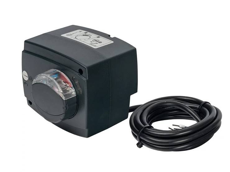
"Feeding" - conducts water in only one direction
A ball or a special rod is used as a shut-off part for it. Adjustment is made either by turning the ball or by moving the stem. To carry out these manipulations, electric drives are used.
The most popular way is a thermostatic head equipped with a water sensor, which regularly monitors the temperature of the heat carrier. Taking into account the received data, the head turns on or off the valve. So, from the return flow, the coolant is supplied regularly, and from the boiler only as needed.
The principle of operation of the device explains the main advantage of the manifold, which is equipped with a supply valve. The floors with this equipment do not overheat, which significantly increases their service life. The low throughput of the valve creates a smooth regulation of the coolant temperature, significant jumps in this case are excluded.
The supply valves are characterized by ease of installation and subsequent operation. They are quite often found in the scheme of self-made collectors for underfloor heating, but they have some limitations in their application. Two-way devices are not advised to be installed in systems that operate in rooms larger than 250 square meters.
Three-way systems
Three-way elements are arranged differently. This equipment integrates the operation of a bypass supply valve and a bypass valve. The valve consists of a body with one inlet and two outlets. For regulation, either a rotating ball or a special stem is used.
The peculiarity of this type of device is that the regulating part shuts off the flow completely, and distributes the incoming water, mixing it. The temperature is adjusted automatically, for this the valve has a drive system that receives signals from different sensors.
Such valves have servo drives
As a rule, 3-way valves are equipped with servo drives, which are controlled by thermostatic sensors or weather-compensated controllers. The servo drive activates the locking mechanism, which is set to the required position to obtain the required indicator of the heated coolant and return flow.
Weather-compensated controllers are required to adjust the system power to the weather. For example, during a severe cold snap, the room will begin to cool down much faster, that is, it will be much more difficult for the heating system to do the job.
To facilitate the task, it is necessary to increase the costs of the heat carrier and increase the temperature. The main disadvantages of three-way elements include a significant throughput. Under these conditions, even a slight shift in regulation can lead to a sharp change in water temperature.
Three-way elements are used for collectors installed in rooms larger than 250 sq. m and systems with a large number of circuits. Moreover, they are used for structures that are equipped with weather-dependent sensors that determine the required floor temperature taking into account atmospheric conditions.
Equipment characteristics
The coolant from the boiler passes through the pipe line to the collector. From it, the liquid enters the floor pipeline. Giving off heat, it returns back to the collector, which has a separate return outlet for the cooled heat carrier. The circulation pump pumps water back into the boiler.
With manual control of the temperature regime, valves are installed on the circuit with cold water and a high temperature coolant. If the room has warmed up well enough, then the hot water valve is closed. If the room is cold, then the valve is opened.
For automatic regulation of the heating mode, a three-way mixer with a thermostat and an external temperature sensor is installed. This system forms a thermostatic valve. It is installed at the inlet to the manifold. The equipment is made of brass or bronze.
- The three-way valve has 3 outlets for hot and cold water and for the heating medium, which is supplied to the floor line. On the body, markers indicate the direction of flows of different temperatures.
- A mixing chamber is provided for mixing liquids of different temperatures.
- A thermostat with a temperature controller is located on the body.
- The temperature sensor is located on the thermostat.
- The valves close off the cold and hot flow outlets. They can be disc-shaped or needle-shaped. Their work depends on the thermostat.
- The thermostat is a system that consists of a liquid capsule and a spring-loaded stem. Valves are attached to it.
- The temperature sensor has a digital panel on which the heating modes are indicated.
We recommend: Should I use Penoplex for underfloor heating?
The thermostat can be located in the thermal head or in the actuator. The devices have a different circuit, but the same principle of operation. The thermal head is a thermostat, which works with the help of a liquid: it is sensitive to temperature changes.
The servos are powered by the electrical network. The liquid is contained in a container. It contains a heating plate. The servo is installed on the manifold.
The three-way mixer is designed for heating systems of large areas. In separate rooms or in country houses, a two-way valve is connected to the collector. It is installed on a circuit with a high temperature coolant. Water flows through it in only one direction.
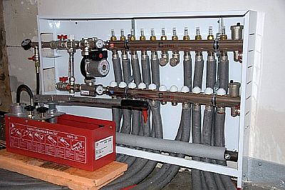
Installing the device
The collector for a warm water floor is mounted according to the following scheme:
- It is necessary to install a frame under the device. It is mounted directly on the wall in a horizontal position or in a specially prepared niche. When choosing a place for installation, one should be guided by the availability of free access to the device to connect the required number of pipelines. Also, a special cabinet is often used for mounting the device. In this form, the device can fit into any room.
- Connection to a heating boiler. The coolant is supplied to the system from the bottom, and the return is placed from the top. Also, in front of the frame, you need to install ball cutoffs. A circulation pump is being installed behind the taps.
- The overflow valve is being installed. It must be equipped with a temperature limiter. A distribution manifold is installed behind this unit.
- Wiring of pipelines to the warm floor is being carried out. The elements through which the coolant will enter the system are placed on top. The pipes from the underfloor heating are installed from the bottom.
- If you intend to install the device with your own hands, it is necessary to connect shut-off valves, which are equipped with a thermostat, to the distribution manifold. When a ready-made kit is being assembled, you do not need to do this.
- The collector is connected to the heating system using compression fittings. This element consists of a clamping ring, a support sleeve and an intermediate nut.
- Manifold pressure testing. After the installation of all structural elements, it is necessary to check how tight the resulting system is. For this, the unit is connected to a circulation pump. It builds up pressure in the system. In this form, the water circuit is left for a day. After this time, check the pressure. If it hasn't changed, then the installation was successful.
Possible problems and their manifestation
A malfunction in the water underfloor heating system manifests itself in a sharp decrease in the level of comfort in the room.
It feels physically:
- Most often no heating, the room gets cold.
- Less commonly, users have to deal with excessive heat, when it becomes unbearably hot, and the heating time of the water-heated floor is significantly reduced. If such a malfunction is not eliminated in time, the floor covering, the screed and the pipes themselves may deteriorate.
The question arises, why does the water heat-insulated floor do not heat well or is there no heating at all?
Often, such problems can arise immediately after the installation of the system at the first start-up. That is why it is important to know the requirements for putting a warm water floor into operation, as well as be able to properly adjust the system.
In order not to worry, wondering how long the warm water floor heats up, it is worth adhering to all the requirements of the installation technology when constructing a "warm pie". One of the possible reasons for the low quality of heat transfer from the system is poor quality thermal insulation.
Periodic energy and temperature logging can be invaluable in identifying the problem. By checking with them, it is much easier to identify a malfunction in time.
Types of floor heating systems
There are two fundamentally different systems, consider their strengths and weaknesses. The choice of a scheme will affect the comfort of staying in residential premises, keep this in mind when making a decision, take into account not only the technical parameters of various schemes, but also the features of the premises and existing heating systems.
Water heat-insulated floor
Allows to obtain uniform floor heating, compatible with some existing heating systems in old buildings. The disadvantages include the complexity of the equipment and installation work and the high estimated cost. In addition, the water system reduces the height of the room by at least 10 cm due to the concrete screed. To create a wiring diagram, the room is divided into separate sections, taking into account the size and configuration of the floor, each circuit must have approximately the same length of pipes, otherwise the heating will be uneven in area. Depending on the construction technology, the water floor can have several installation schemes.
- On a concrete base. Consists of a layer of thermal insulation on a concrete base, a metal mesh for laying pipes, pipelines, an upper screed and a finishing floor covering.
- Polystyrene. There is no need to do a more modern method of laying a water-heated floor, a cement-sand screed. Special polystyrene plates with places for fixing plastic pipelines are laid on the heat-insulating layer. The finished wiring is covered with gypsum fiber boards, on which the finishing flooring is laid.
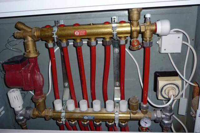
A common disadvantage of water floor heating is that emergencies have very serious consequences.The most complex elements of a water-heated floor are a mixing unit and a manifold.
Description of types of mixing units
The mixing unit provides a constant and balanced circulation of heated water along the laid circuits, changes the speed of movement, independently maintains the set temperature for heating the floor and the heat carrier. Depending on the design features, it can have several types:
- with a series connection of a water pump and a two-way thermal valve;
- with a series connection of a water pump and a three-way thermal valve;
- with a series connection of a water pump, a three-way thermal valve operates with flows converging in one node;
- with parallel connection of a water pump, two-way thermal valve;
- the water pump is connected in parallel, the thermal valve is three-way.
Mixing unit for underfloor heating
Each scheme has its own characteristics, the selection is carried out taking into account the technical parameters and the number of heating circuits.
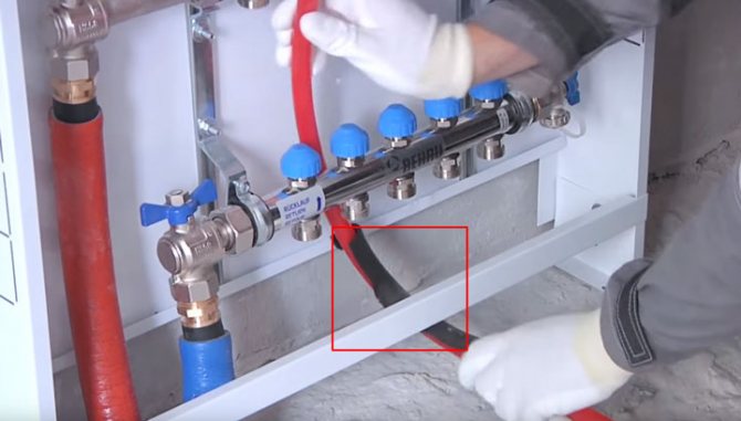
Layout of pipes for radiators and warm water floor
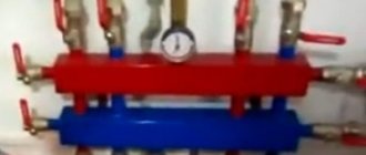
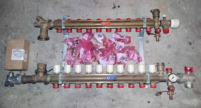
Distribution manifolds
Designed to connect all heating devices of the underfloor heating system in one place. Depending on the nomenclature and the number of additional special equipment, they can be simple and improved. Simple ones do not have any fittings and are only used to connect fittings. The improved ones have control sensors, performance devices, measuring instruments, etc.
General principles of adjustment
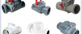
Three-way mixing valves, depending on the type of control mechanism, are divided into several types:
- Standard. Regulation in such devices is carried out by expanding the coolant in the pipeline. The liquid in the system heats up to maximum values and pressure occurs on the obturator in the valve blocking the access of cold water. As a result, the sash opens and the cooled stream mixes with the hot heat carrier. The accuracy of the workflow for such products is not high.
- With thermal head. The design of the three-way valve includes a thermal head, which is equipped with a special sensitive element that reacts not only to the temperature of the liquid in the system but also to the heating parameters of the air masses.
- Electrical. In valves with an electric drive, the commands are given by the controller, which activates the temperature sensors without additional devices.
- Electronic. The regulation of the temperature regime with such a valve is carried out thanks to the built-in electric motor and a control device equipped with thermometers.
The most common are mixing valves with a thermal head. They are equipped with a sensor and do not require any additional electrical connection. At the same time, the device is distinguished by its accuracy and durability. Standard valves are installed when water is supplied to a system with a constant temperature regime.
Installing a 3-way valve requires careful handling. Incorrect connection of the mixing device can cause not only a decrease in the efficiency of the working process of the warm floor, but also lead to emergency failures of all heating equipment. Therefore, in the absence of skills, independent installation of the valve is not recommended.