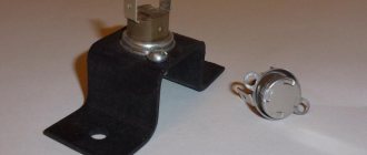
The three-way valve is a device widely used in a wide variety of designs of household and industrial devices. Accordingly, the same kind of device is used in household gas equipment. Along with various malfunctions of household gas boilers, users often encounter a breakdown of a three-way valve. Agree, it would be nice to find out why this device fails and try to fix it on your own.
Meanwhile, it is not always possible even for professional mechanics to establish the loss of device performance “at first sight”. This requires an appropriate check. Therefore, within the framework of our article, we will consider how to check a three-way valve in a gas boiler when there is a suspicion of a malfunction of this mechanism. Let's also talk about the types of the device and its functionality.
Safety valve use
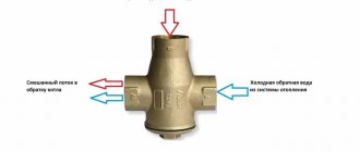
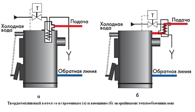
It is not the same as a safety valve. The latter simply relieves pressure in the system, but does not cool it. Another thing is the boiler overheating protection valve, which takes hot water from the system, and instead supplies cold water from the water supply. The device is non-volatile, it is connected to the supply and return mains, water supply network and sewerage system.
At a coolant temperature above 105 ºС, the valve opens and, due to a pressure in the water supply system of 2-5 bar, hot water is displaced from the jacket of the heat generator and cold pipelines, after which it goes into the sewage system. How the solid fuel boiler protection valve is connected is shown in the diagram:
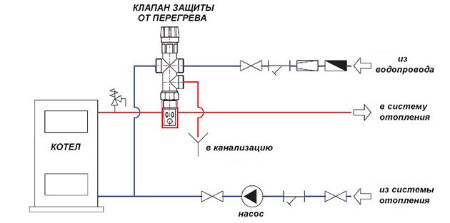
The disadvantage of this protection method is that it is not suitable for systems filled with antifreeze liquid. In addition, the scheme is not applicable in conditions where there is no centralized water supply, because together with a power outage, the supply of water from a well or a pool will also stop.


What is the danger of condensate for the boiler
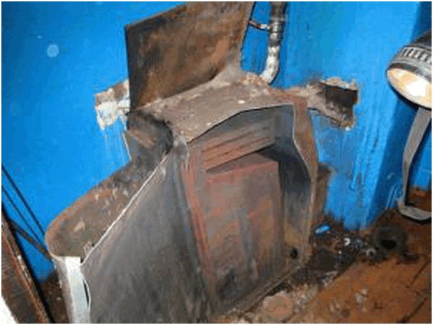
When firing up a solid fuel boiler, one has to face the fact that a cold coolant washes the walls of an already heated combustion chamber, cools them, which leads to condensation of water vapor, which is invariably present in the flue gases. Particles of water interacting with flue gases form acids, which leads to the destruction of the inner surface of the combustion chamber and chimney.
But the negative effect of condensate is not limited to this: soot particles that settle on the walls dissolve in water drops. Under the influence of high temperatures, this mixture is sintered, forming a dense and strong crust on the inner surface of the combustion chamber, the presence of which sharply reduces the intensity of heat exchange between the flue gases and the coolant. The boiler efficiency drops.
Removing the crust is not easy, especially if the boiler's combustion chamber has a complex heat transfer surface.
It is impossible to completely eliminate the formation of condensate in a solid fuel boiler, but the duration of this process can be significantly reduced.
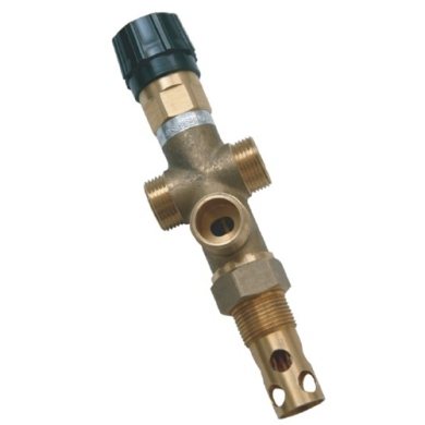
Design
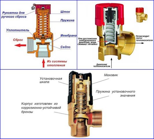
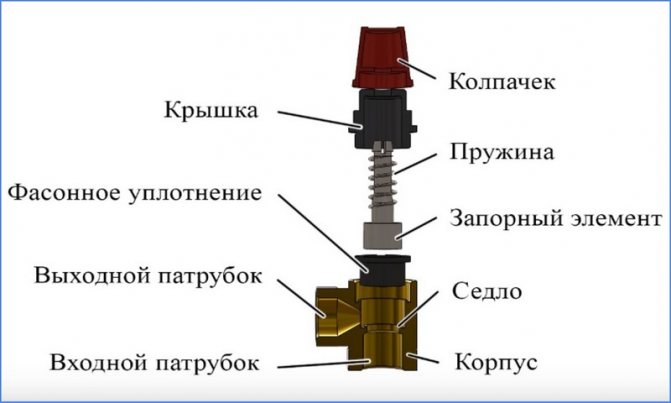
A typical boiler safety valve has a collapsible design and consists of the following main elements:
Housing. It is usually made of brass and looks like a tee. On its sides there are a lower threaded inlet, a lateral outlet pipe and an upper seat, on which the shaped seal is seated.
Locking group.It is a spring-loaded pulley with a cylindrical (disk) end locking element, on which an elastic rubber seal in the form of a cup (disk) is put on.
Cap. A black heat-resistant polymer cover is screwed into the upper threaded branch pipe of the brass body, which holds the spring-loaded stem in the working position. On the upper edges of the lid there are projections along which the top cap shaped in the lower part, connected to the shut-off rod, slides. When turned through a certain angle, the cap rises together with the stem and opens the side branch pipe - this allows the safety valve to be used for heating always open in manual mode.
Cap. The polymer part is usually red in color with a ribbed lateral surface, screwed to a hollow stem with a screw. The shallow protrusions in the lower part of the cap, when it rotates, fall on the teeth of the cap - the handle rises together with the spring-loaded shutter and opens the side channel, allowing manual pressure relief.
Adjusting washer. The inner wall of the cover has a thread, in which the adjustment nut rotates, when it is lowered down, it compresses the spring - thus increasing the valve response threshold. By unscrewing the nut upwards, the spring is weakened and the response pressure decreases. For turning, the nut is equipped with a transverse slot in the upper part for a flat screwdriver.
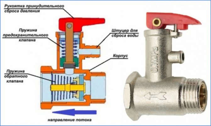
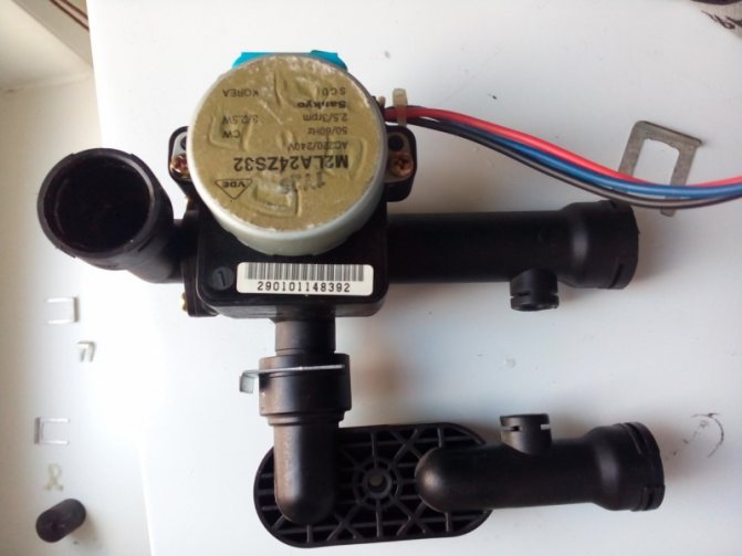
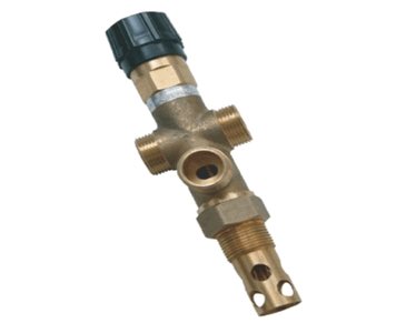
Valve for water heating boilers - design and appearance
Principle of operation and types of valve actuators
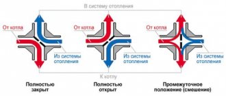
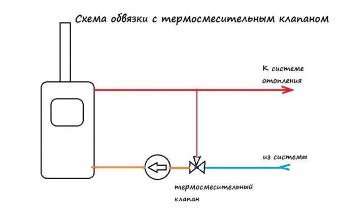
The product is produced in different configurations and with different actuators, but the principle of operation of the three-way valve remains the same: mix two streams with different temperatures into one, the temperature of which is set by the user or is required according to the scheme. The liquid inside the valve flows from one branch pipe to another until its temperature changes and reaches the set value. The actuator then gradually opens the flow from the third port, keeping the leaving water temperature within the set value. On this basis, such a valve is called a three-way valve.
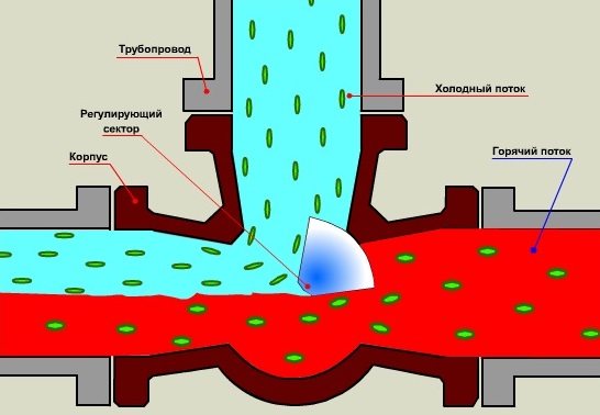
Three-way valve working principle
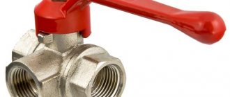
Any 3-way mixing valve has two inlets and one outlet. The distribution of streams is carried out using a drive, which is of several types:
- The thermostatic actuator (thermostat) is one of the most popular, it works due to thermal expansion of the sensing element, as a result of which there is a pressure on the valve stem and the liquid begins to mix.
- A widespread type of actuator, which is installed in a three-way changeover valve, is electric, it operates from a signal from the control unit.
- The valve can be operated by pushing the stem down with the thermostatic head actuator. It reacts to the air temperature, which is determined by itself or with the help of an external sensor and a capillary tube. The drive is most commonly used in underfloor heating systems.
Stationary solid fuel boilers cannot be directly connected to the heating system. One of the reasons is that cold water must not be allowed to enter the boiler jacket until it has warmed up. Otherwise, condensate is released on the walls of the furnace, which, mixing with the ash, forms a strong layer of carbon. It prevents free heat exchange, reducing the efficiency of the installation, and it is very difficult to remove carbon deposits. The second reason is that you need to protect cast-iron furnaces from temperature drops in the event of an unexpected shutdown of the pump due to a power outage, and then start it up. The task is not to let cold water into the hot boiler, for which a three-way valve is needed.It will make the coolant circulate in a small circle until it heats up, and only then will it mix in cold water.
Where are 3-way valves used?
There are valves of this type in different schemes. They are included in the wiring diagram of underfloor heating to ensure uniform heating of all its sections and to exclude overheating of individual branches.
In the case of a solid fuel boiler, condensation is often observed in its chamber. The installation of a three-way valve will help to deal with it.
A three-way device in the heating system works effectively when there is a need to connect a DHW circuit and separate heat flows.
The use of a valve in the piping of radiators eliminates the need for a bypass. Installing it on the return line creates conditions for a short circuit device.
How to choose the right one
Before proceeding with the direct purchase of a valve, you should find out a lot of points regarding the boiler used and the features of the heating system, this will increase the efficiency of the system, otherwise it can lead to a deterioration in standard performance.
The main thing in this matter is to determine the operating parameters of the coolant (this is easy to find out using the available documentation). In addition, it is necessary to take into account the heating consumption and the piping scheme itself.
You can determine the flow rate and temperature of the coolant using the design documentation. If there is none, you can use the recommendations that are indicated in the passport of the boiler itself, which is used in the system.
All these parameters are needed in order to choose the right valve (you have to choose purely in terms of throughput).
The drive control system is selected according to the type of heating system and the piping of the boiler itself. The simplest models and options involve the use of a conventional thermostatic valve (although there are exceptions). And, as already mentioned, to ensure high-quality operation of floor heating, you should use a product with a thermostatic head.
If you plan to work with a complex piping system, then manufacturers recommend using a valve with an external control controller.
Be that as it may, any modern heating system must use a three-way valve, which is an important component in the entire system and there is simply nothing to replace it with - no alternative has been invented.
An exception can be called the previously used elevator systems, which have not been used for a long time and are considered obsolete (due to their low efficiency and convenience).
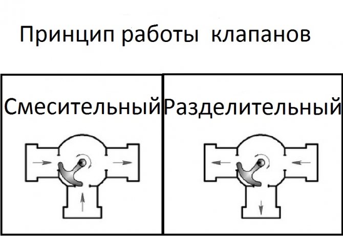
Be sure to take into account that there is not only a mixing valve, but also a separation valve. The first option considered above implies the possibility of mixing two streams into one, and the second option, a separating valve, offers the ability to divide one stream into two, while regulating the flow to each of the outlets.
Both of these types of valves can be used in the system. However, a mixing valve is necessary in any case, and a separating one is rarely used in simple heating systems.
The correct choice of valve can be called in the event that the user chooses to purchase not only in terms of throughput, but also in terms of temperature. If the first selection criterion is the main one - without taking it into account, one cannot count on the functionality of the system as a whole, then the second criterion implies the duration of the valve's operation - if it is not designed to function in a system where the temperature is higher than the allowable temperature of the valve itself - the part will wear out faster and will require replacement, or will not function at all.
An autonomous heating system is a much more complex mechanism, consisting of a large number of interconnected components and assemblies that perform the corresponding functions. The three-way valve for the boiler in this mechanism plays the role of a mixer, in which the temperature of the coolant is regulated.
This is done so that the pipes are evenly heated and the heating level in each room is approximately the same. If you do not use the part, it will turn out that the water, when passing through the heat exchanger, will not heat up equally, and as a result, some of the rooms will receive less heat energy than all other rooms.
Conclusions and useful video on the topic
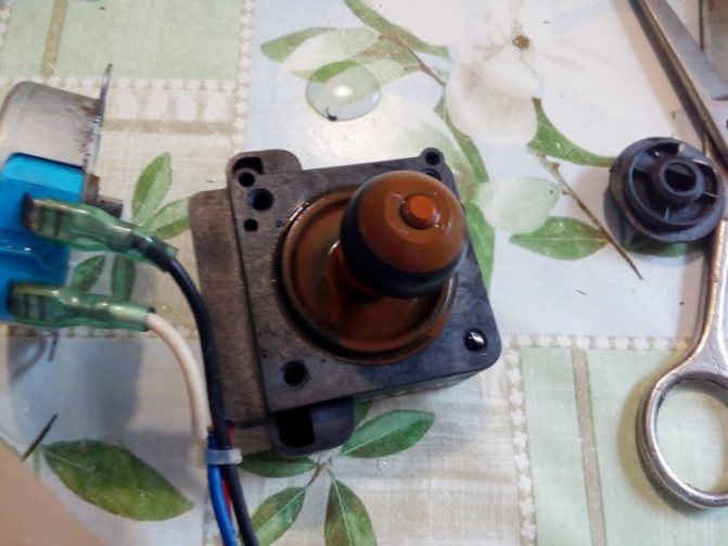
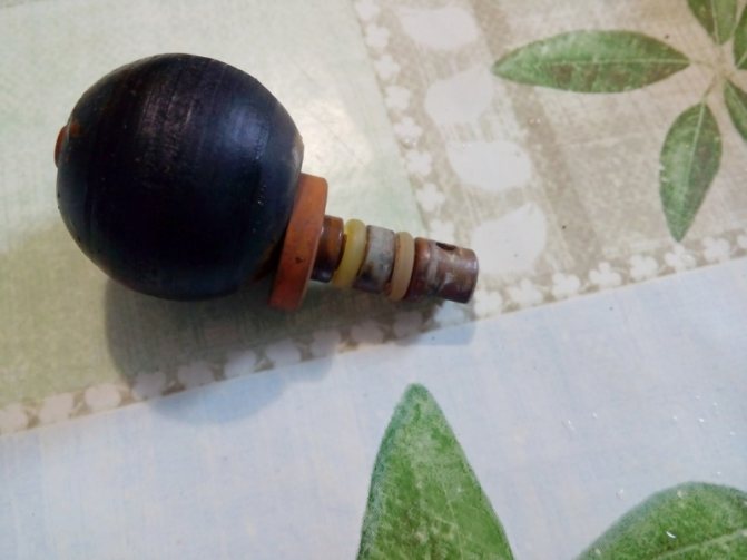
Below is a useful video material for your reference, which demonstrates the disassembly of a device that regulates heat flows in a gas boiler. Moreover, the practice of disassembling with your own hands is given.
The distribution device described in the video is equipped with a hydraulic rod drive. Familiarization with this repair practice will help you understand how to check devices of a similar type and repair if defects are found.
Thus, a three-way valve for a domestic gas boiler can be tested in almost any design, regardless of the individual design. The main point is to correctly determine with which drive the switchgear of the gas boiler is used. Information on this issue can be obtained from the documentation for the equipment or relying on the examples of the drive demonstrations in this article.
Do you have useful information on the topic discussed above and would like to share it with other users? Write your remarks and comments in the block below, add photos, leave your recommendations - the feedback form is located below.
Reasons that may result in overheating of a solid fuel boiler
Even at the stage of selection and purchase, it is important to take into account the operational characteristics of the heating device. Many models that are on sale today have a built-in overheating protection system
Whether it works or not is the second question. However, it is necessary to adhere to certain knowledge and skills, hoping to create an efficient and safe autonomous heating system at home.
The reliable operation of the heating unit depends on the operating conditions. In case of obvious violations of the technological parameters of heating equipment and abuse of standard safety rules, there is a high probability of an emergency.
Possible negative consequences can be prevented even at the stage of installing a solid fuel boiler. Correct piping of the heating device will guarantee your safety and reliable operation of the unit in the future.
In detail, in each case, the solid fuel boiler protection system has its own specifics and features. Each heating system has its own pros and cons. For instance:
When it comes to solid fuel boilers with natural circulation of the coolant, it is necessary to take care of the safety and operability of the heating equipment even during installation. The pipes in the system are installed metal. Moreover, the diameter of such pipes must exceed the diameter of the pipes used for laying a circuit with forced circulation of the coolant. Sensors installed on the water circuit will signal a possible overheating of the coolant. The safety valve and expansion vessel act as a compensator, reducing overpressure in the system.
A significant disadvantage of the gravitational heating system is the lack of an effective mechanism for adjusting the operating modes of solid fuel boilers.
Large technological opportunities for consumers are provided by those working with forced circulation of the coolant in the system.Already only the presence of the second circuit significantly increases the ability to regulate the heating temperature of the boiler water. The only drawback in the operation of such a system is a working pump, which can make it difficult to operate the heating system with its work.
This is due to the fact that when the electricity is cut off, the pump stops performing its functions. The stoppage of the circulation process and the inertia of solid fuel heating boilers can lead to overheating of the heating unit. If the boiler equipment is not equipped, the situation with a power outage is fraught with extremely unpleasant consequences.
Effective protection against overheating of a working solid fuel boiler should be based on the mechanism for removing excess heat generated by the heating device.
What are the ways to protect heating equipment from overheating
Manufacturing companies try, in order to increase the consumer attractiveness of their products, to include any guarantees of its safety in the technical passport of boiler equipment. The uninitiated consumer does not have the slightest idea about the means of protecting the heating boiler from boiling.
There are currently the following ways to ensure the protection of solid fuel units used for autonomous heating systems. The effectiveness of each method is explained by the operating conditions of the boiler equipment, and the design features of the units.
In most cases, manufacturers recommend using tap water for cooling in the data sheet for a heater. In some cases, solid fuel boilers are equipped with built-in additional heat exchangers. There are models of boilers with external heat exchangers. Used by a safety valve to prevent overheating. The safety valve is designed only to relieve excessive pressure in the system, while the safety valve opens access to tap water when the boiler overheats.
If the temperature of the coolant exceeds the 100 ° C mark, it creates an excess pressure that opens the valve. Under the influence of tap water, which is supplied under a pressure of 2-5 bar, hot water from the circuit is displaced by cold water.
The first controversial aspect of tap water cooling is the lack of electricity to power the pump. The expansion vessel does not have enough water to cool the boiler.
The second aspect, which sweeps aside this cooling method, is associated with the use of antifreeze as a heat carrier. In the event of an emergency situation, up to 150 liters of antifreeze will go into the sewer along with the incoming cold water. Is this protection method worth it?
The presence of a UPS will allow maintaining the operation of the circulating pump in a critical situation, with the help of which the coolant will evenly disperse through the pipeline, without having time to overheat. As long as there is enough battery capacity, an uninterruptible power supply ensures that the pump is running. During this time, the boiler should not have time to heat up to the critical parameters, the automation will work, starting the water along the spare, emergency circuit.
Another way to get out of a critical situation will be to install an emergency circuit in the piping of a solid fuel unit. Switching off the pump can be duplicated by the operation of the reserve circuit with natural circulation of the coolant. The role of the emergency circuit is not in providing heating of residential premises, but only in the ability to remove excess heat energy in an emergency.
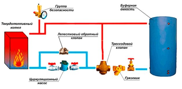
Such a scheme for organizing the protection of the heating unit from overheating is reliable, simple and convenient in operation. You will not need special funds for its equipment and installation.The only conditions for such protection to work are:
- the presence of an expansion tank or storage tank in the system;
- use of a check valve only of the petal type;
- the pipes in the secondary circuit must be of a larger diameter than the conventional heating circuit.
How to install
When installing the safety drain fittings, observe the following rules:
- Usually, a pressure relief valve in the heating system is installed in a household circuit in a single copy. Its main points of placement are directly above an electric, solid fuel, gas boiler at its outlet or next to a horizontally located pipeline. If this is not possible for technical reasons, the main condition for correct installation is installation in the supply line up to the first shut-off valve.
- The outlet side pipe is usually connected to a sewer or drainage system, if it is technically difficult or the volume of the coolant in the circuit is not high, you can use a flexible hose, which is lowered into a container of a suitable volume.
- The liquid must be removed with a rupture of the jet through a funnel or a hydraulic seal to ensure the system is operational when the sewer is clogged.
- For installation in a pipeline, use a BOTTOM tee of a suitable diameter, the standard being 1/2, 3/4, 1 and 2 inches. The diameter of the pipeline inlet to the valve must not be less than that of the system.
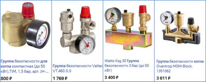
Valve safety groups - varieties and price
Elimination of common mistakes
Let's take a look at the common errors of Navien boilers and see how to fix them.
Error "02" - stopping the circulation of the coolant
Often the filters of the boiler or heating system are clogged, this leads to the appearance of two unfortunate numbers of malfunction 02. It is also very likely that the cause of this error is the main heat exchanger clogged with scale. These troubles occur due to the high hardness of the water used to operate the device. The ubiquitous scale attacks critical parts of the appliance, stopping work. To resume boiler operation, you must:
- Clean the filters in the boiler itself and in the heating system.
- Remove the heat exchanger from the housing.
- Prepare an acidic solution to remove limescale deposits on the heat exchanger.
- Place the heat exchanger in a container with acid solution.
- Wait until chemistry does the job.
After simple manipulations, if you have the necessary ingredients and knowledge, you can independently get rid of the error "02" of the Navien gas boiler. Keep an eye on the circulation sensor inside the boiler, rinse the filters regularly to avoid unpleasant surprises.
Error "03" ignition problems
He talks about either a simple lack of gas, or a breakdown of the gas valve. Let's analyze the second option. The most reliable Japanese gas valves are installed in Navien boilers, it is difficult to break them perfectly using the boiler correctly. But if the mains voltage is ten to twenty volts higher than 220 volts, the coils inside the boiler will turn black, the valve may completely break. To fix this breakdown, you will have to buy a completely new valve and replace the broken part. Extreme care is required with the mains voltage, Increased indicators can harm more than one boiler.
Valve types
So, in more detail about the two existing types of valves, you can read below:
- 1. The three-way thermostatic valve for the boiler is an automatic model. It will maintain the set temperature level without additional human intervention. At the same time, the most functional models are equipped with an additional security system that blocks the movement of the coolant if there is no circulation through one of the incoming pipes. Thus, boiling will not occur in the batteries.
- 2.The three-way thermo-mixing valve for the boiler can be completed with both automatic and manual control. The fundamental difference will be the need to regularly check the state of the system so that it does not overheat. To date, mechanical devices have already practically been abandoned, since they have been replaced by more advanced units.
Varieties
The existing types of valves are capable of working with boiler equipment from leading foreign (Vaillant, Baxi, Ariston, Navien, Viessmann) and domestic (Nevalux) manufacturers on gas, liquid and solid fuels in situations where automatic control over the operation of the system is difficult due to the type of fuel. or broken when the automation fails. Depending on the design and the principle of operation, safety valves are divided into the following groups:
- According to the purpose of the equipment in which they are installed:
- For heating boilers, they have the above design, they are often supplied on fittings in the form of a tee, in which a pressure gauge for checking the pressure and a vent valve are additionally installed.
- For hot water boilers, there is a flag in the design for draining water.
- Containers and pressure vessels.
- Pressure pipelines.
- According to the principle of actuation of the pressure mechanism:
- From a spring, the clamping force of which is regulated by an external or internal nut (its work is discussed above).
- Lever-cargo, used in industrial heating systems designed to discharge large volumes of water, their response threshold can be adjusted with suspended weights. They are suspended from a handle connected to the shut-off valve by the principle of a lever.
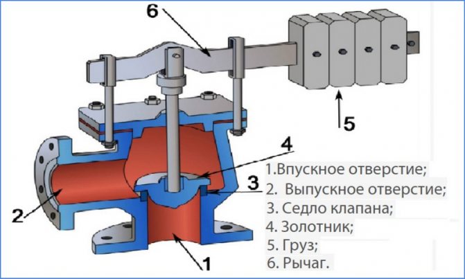
Lever-load modification device
- Locking mechanism response speeds:
- Proportional (low-lift spring) - the sealed lock rises in proportion to the pressure and is linearly related to its increase, while the drain hole gradually opens and closes in the same way with a decrease in the volume of the coolant. The advantage of the design is the absence of water hammer at various modes of movement of the shut-off valve.
- Two-position (full-lift lever-cargo) - operate in open-closed positions. When the pressure exceeds the response threshold, the outlet opens completely and the excess volume of the coolant is vented. After the pressure in the system is normalized, the outlet is completely closed, the main design flaw is the presence of water hammer.
- By adjustment:
- Non-adjustable (with caps of different colors).
- Adjustable with screw parts.
- According to the design of the adjusting elements of the compression of the spring with:
- An internal washer, the principle of operation of which was discussed above.
- Outside screw, nut, models are used in household and communal heating systems with large volumes of coolant.
- With a handle, a similar control system is used in flanged industrial valves, when the handle is fully raised, a one-time drain of water can be performed.
Designs of various models of drain valves
Major malfunctions and repair methods
Loss of GK functionality leads to the shutdown of all boiler equipment of heating equipment, or partial, when it is impossible to adjust the required heating level in the room, due to the partial opening of the membrane.
Sometimes situations occur that, on the contrary, lead to a continuous supply of fuel to the burner, when the gas-air valve is constantly open.
All of the above failures must be immediately eliminated, as they can create an emergency in the house. If the user does not know what to do with the faulty valve, immediately close the gas inlet valve, thoroughly ventilate the room and call the representatives of the gas company.
Checking electrical components
It is permissible to test the functionality of the electromagnetic main battery of the cut-off device without dismantling. To perform a check directly on the boiler, you need to turn off the gas supply by turning the valve on the gas pipeline.
The boiler can also remain connected to the power supply. On the regulator of the fuel supply to the burner, there is an electronic unit - a microswitch, which, when the heater is turned on, supplies power to the main technological components.

Microswitch
Voltage supply zones by microswitch:
- ignition system device;
- fan heater;
- electromagnetic coil.
In the event that, by force, for example, with a screwdriver, act on the hydraulic pusher plate of the microswitch, power will be supplied to the boiler automation system.
As a result, the activity of subsequent elements is activated, for example, at the gas valve for the Baxi boiler:
- fan;
- piezo ignition;
- solenoid shut-off valve.
The inspector will hear the sound of a turned on fan, a clicking sound of a piezo ignition and a distinctive click of the valve stem. A similar position of the device shows the performance of the elements, at least in terms of the electrical part.
Kau triple thermostatic valve
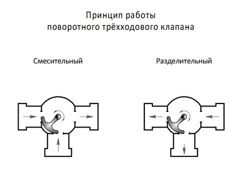
There are two types of thermostatic valves:
- mixing
- flow A entering the valve is divided into flow B and flow AB - distributive
- stream A entering the valve is divided into 2 streams
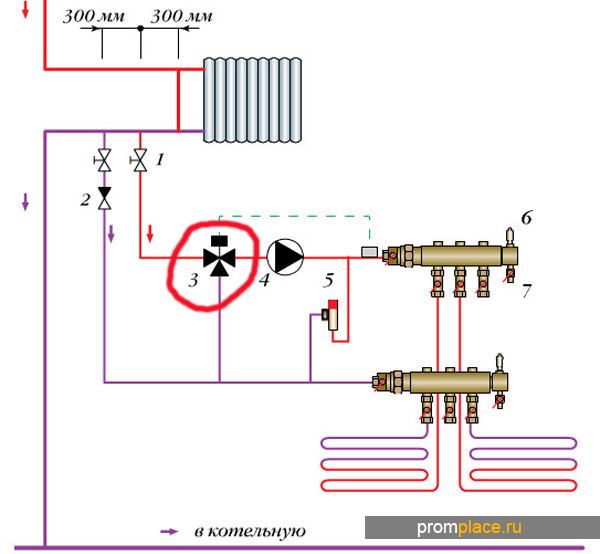
The mixing valve is installed in the return pipe and the control valve is installed in the supply pipe. The valve is controlled by a thermal head with a thermal bulb.
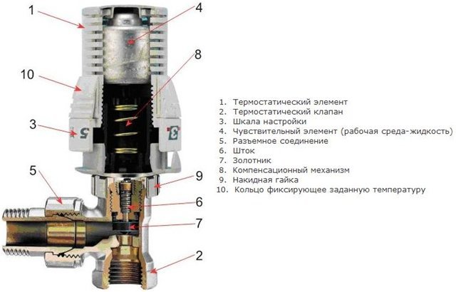
The thermo bulb with the help of a special sleeve is attached to the surface of the return pipe in close proximity to the heating boiler. Inside the flask there is a working fluid, the temperature of which is equal to the temperature of the coolant before entering the boiler. If the temperature of the coolant rises, the working fluid increases in volume, and, conversely, when the temperature of the coolant decreases, the volume of the working fluid decreases. Expanding or contracting, the working fluid presses on the stem, closing or opening the thermostatic valve.
With the help of the thermal head, you can set a certain temperature, above (below) which the heating medium will not be heated. How to set the temperature by choosing the operating modes of the thermal head is described in detail in the instructions for it.
Another feature of the thermostatic valve is that it reduces the flow of the coolant to the boiler, but never blocks it or opens it completely, protecting the boiler from overheating and boiling. The valve is fully closed only at the moment of starting the boiler.
The nuances of choosing a device
The following guidelines are common when choosing a suitable 3-way valve:
- Reputable manufacturers are preferred. Often on the market there are low-quality valves from unknown companies.
- Copper or brass products are more wear-resistant.
- Manual controls are more reliable, but less functional.
The key point is the technical parameters of the system in which it is supposed to be installed. The following characteristics are taken into account: the pressure level, the highest temperature of the coolant at the point of installation of the device, the permissible pressure drop, the volume of water passing through the valve.
Only a properly sized valve will work well. To do this, you need to compare the performance of your plumbing system with the coefficient of throughput of the device. It is mandatory marked on each model.
For rooms of limited area, such as a bathroom, it is irrational to choose an expensive valve with a thermo mixer.
On large areas with warm floors, a device with automatic temperature control is required. The reference for selection should also be the conformity of the product GOST 12894-2005.
The cost can be very different, it all depends on the manufacturer.
In country houses with an installed solid fuel boiler, the heating scheme is not very complicated. A three-way valve with a simplified design is fine here.
It functions autonomously and does not have a thermal head, sensor, or even a rod. The thermostatic element that controls its operation is set to a certain temperature and is located in the housing.
Thermal mixing valve design and operating principle
Like most parts and structural elements of a solid fuel boiler, a three-way or also has a simple and understandable design. It includes:
- main building;
- spring loaded stem;
- two dampers, disc type;
- thermostatic element (head with fixed positions).
The diagram shows the mechanism in detail in a section, where and how its main elements are located.
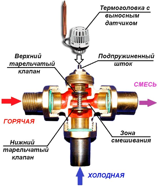
Looking at the design of the device, it is not hard to understand the principle of operation. Let's consider in more detail the ongoing processes.
In the normal operating mode of the heating system, the main dampers located linearly are in the open position. Insufficiently hot water flows freely from the boiler into the heating circuit.
The thermostatic head, equipped with a temperature-sensitive liquid sensor, is in the standard position. In the event of an emergency situation, for example: from the side of the boiler, a coolant begins to flow into the system, the temperature of which exceeds the specified parameters. The temperature control sensor is triggered, driving the stem. The operating mechanism closes the main, direct-flow passage, simultaneously opening the passage from the side, through which cold water enters. As a result of mixing water of different temperatures, the temperature is equalized to the set rate. The coolant, already at normal temperature, leaves the device through a pipe to the heating system. The adjustment of the thermostatic head of the device is determined by the degree to which the bellows with the expanding liquid is pressed on the stem. Determines the sensitivity of the device accordingly.
The moment the device is triggered is determined by adjusting the head set to a certain temperature.
If the water continues to heat up as a result of the actions taken, the device shuts off the main inlet flow, opening the access of cold water from the third pipe. The stem in this case is in the lowest position. Water from the third branch pipe is already mixed into the main stream. When the temperature of the coolant changes downward, the stem under the action of the sensor reduces the pressure, opening access to hot water.
In order to achieve the correct operation of the entire mechanism, it is necessary to precisely comply with the requirements for its installation. It can be installed in a right-hand or left-hand version, both on the return and on the supply circuit. During operation, the device does not require maintenance at all.
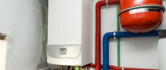
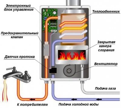
The device of a double-circuit gas boiler
In order to understand the principle of operation of a gas double-circuit boiler, you need to understand its structure. It consists of many individual modules that heat the heating medium in the heating circuit and switch over to the DHW circuit. The well-coordinated work of all components allows you to count on trouble-free operation of the equipment. Knowing the device of a double-circuit boiler, you can understand its principle of operation.
We will not consider the device of double-circuit boilers with an accuracy of a screw, since it is enough for us to understand the purpose of the main units. Inside the boiler we will find:
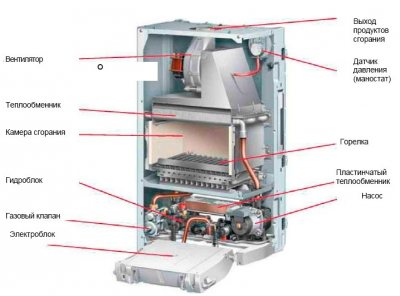
The device of models with two circuits: heating and DHW circuit.
- A burner located in an open or closed combustion chamber - this is the heart of any heating boiler... It heats the heating medium and generates heat for the operation of the DHW circuit. To ensure accurate maintenance of the set temperature, it is endowed with an electronic flame modulation system;
- Combustion chamber - the above burner is located in it. It can be open or closed. In a closed combustion chamber (or rather, above it), we will find a fan responsible for blowing air and removing combustion products. It is he who is the source of quiet noise when the boiler is turned on;
- Circulation pump - provides forced circulation of the coolant through the heating system and during the operation of the DHW circuit. Unlike the combustion chamber fan, the pump is not a source of noise and operates as quietly as possible;
- Three-way valve - it is this thing that is responsible for switching the system to the hot water generation mode;
- The main heat exchanger - in the device of a double-circuit wall-mounted gas boiler, it is located above the burner, in the combustion chamber. Here, the heating medium used in the heating circuit or in the DHW circuit for heating water is heated;
- Secondary heat exchanger - it is in it that hot water is prepared;
- Automation - it controls the parameters of the equipment, checks the temperature of the coolant and hot water, controls the modulation, turns on and off various nodes, monitors the presence of a flame, fixes errors and performs other useful functions.
In the lower part of the housings, there are nozzles for connecting the heating system, pipes with cold water, pipes with hot water and gas.
You can see that the device of the gas water heater differs only in the absence of a heating circuit.
We found out the device of a double-circuit wall-mounted gas boiler - it seems a little complicated, but if you understand the purpose of certain nodes, then the difficulties will disappear. Here we can note the similarity with a gas instantaneous water heater, from which a burner with a heat exchanger remains here. Everything else is taken from wall-mounted single-circuit boilers. Undoubted the advantage is the presence of a built-in piping - this is an expansion tank, a circulation pump and a safety group.
Analyzing the principle of operation and the device of a gas double-circuit boiler, it should be noted that the water from the DHW circuit never mixes with the coolant. The coolant is poured into the heating system through a separate pipe connected to the heating. Hot water is prepared by part of the heating medium circulating through a secondary heat exchanger. However, we will talk about this a little later.
Why the valve can leak
The pressure relief valve in the heating system can leak for various reasons. In some situations, this is an acceptable natural process, in other cases, a leak indicates a malfunction of the device.
Leakage of the protection valve can be caused by the following reasons:
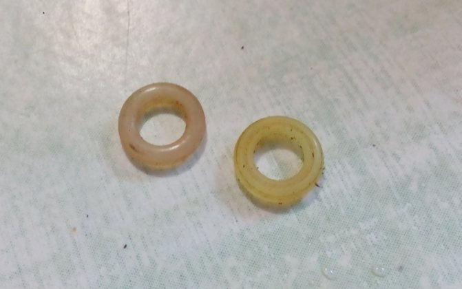
- Damage to the sealed rubber cup, disc as a result of repeated use. If during repair the replacement part cannot be found on sale or it is not included in the package, you will have to change the device completely.
- In spring types, the opening of the side drain pipe occurs gradually, with boundary pressure values or short-term surges, the valve may partially work and drip, which does not indicate a malfunction.
- Leakage can be caused by incorrect settings or malfunctions of the expansion tank - damage to its membrane, air escaping through a depressurized housing or a damaged nipple. In this case, sudden pressure surges are possible as a result of water hammer, causing periodic short-term flow of the coolant through the safety valve.
- Some adjustable valves are leaking because fluid seeps down the stem from the top during actuation.
- If a back pressure is created at the branch pipe above the instrument response threshold, a leak also occurs.
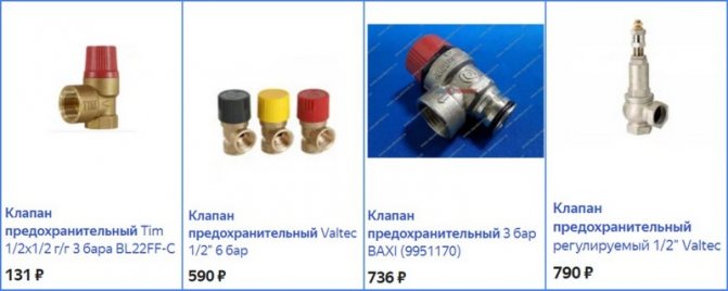
Appearance, cost of some brands of drain valves
The safety valve of steam boilers is designed to protect them from overpressure in the system caused by various factors, and is an indispensable element in the operation of this type of equipment. A wide range of safety devices from Chinese, domestic and European manufacturers are available for sale at a relatively low cost. When buying, it is rational to choose a protective group from several devices, which additionally include a pressure gauge and an air bleed valve.
Signs and types of breakdowns
The problems of double-circuit and single-circuit boilers "Ariston", "Ferroli", "Lemax" can be different:
- Intermittent faults. Occurs when external parameters do not match the operating settings of the device. For example, due to power surges in the network;
- Primary and secondary. The first time the code appears on the screen, it indicates a problem with the system. If the problem persists, the error will appear a second time;
- Obvious and non-obvious. On examination, damage to the heat exchanger can be seen. But there are such problems - a leak, an increase in pressure - the causes of which can only be detected by a specialist;
- Sudden and gradual. In the first case, the technique may shut down without warning signs. In the second, the reasons are wear of parts.
Water dripping from the safety valve. What to do
Accumulative water heaters today are in great demand among our compatriots. These units simply allow them to effectively solve many economic problems, but sometimes it happens that the device itself becomes the source of the problem.
One of the most common problems that one has to face is water leakage. If water drips from the safety valve, then, as soon as possible, it is necessary to establish the cause, because in some cases this process should not be considered a malfunction. That is why there is no need to rush to the decision to call a water heater repair specialist.
Possible causes of the malfunction
The reasons for water leakage from the valve can be:
- Valve malfunction;
- Incorrectly set pressure difference in the system;
- Other reasons, in particular, water may flow out of the valve, but this will not be considered a failure.
The first two reasons involve the repair of the unit.
Troubleshooting methods
Gas water heaters should be tested first. It is necessary to determine in what situation the outflow of water occurs.
If you noticed that water flows out during the heating of water, then, most likely, your unit is completely operational. The fact is that when heated, the water expands, respectively, the pressure of the liquid on the tank walls increases
When the pressure exceeds the norm, the valve gets rid of excess water. The solution to this problem can be the connection of a rubber hose and its output to the sewer or a container of the required size.
If the safety valve of the water heater passes cold water, then most likely the reason is that the pressure in the water supply is too high. The solution to this problem is to install a reducer to normalize the pressure in the water supply network. To do this, you must contact a qualified specialist. Also, you cannot do without the help of a professional if you are inclined to conclude that the cause of the water leak is a malfunction of the valve itself.
Thus, the first step to solving problems with water leakage from a water heater is to establish the cause of the leakage and establish the nature of the malfunction.Remember that it is always safer to turn to a professional for help than to repair complex equipment on your own, because inept repairs can lead to a more complex malfunction.
What can be repaired without gas workers
In the complex of the automation system of boiler equipment, the gas valve is one of the most critical units, on which not only the efficiency of the boiler operation depends, but also the safety of equipment and human living conditions. Incorrect functioning of gas devices very often leads to explosions and fires.
Solenoid valve malfunctions occur due to:
- line jump in the power supply of the boiler;
- the existence of sources of wandering currents;
- clogging of the shut-off valve with foreign elements;
- the presence of condensate in the gas pipeline.
If the work on identifying and eliminating the malfunction of the gas valve can lead to a gas leak during repair or after, it is extremely important to contact the gas service and service center. As this may be due to the loss of the right to warranty service.
However, there are a number of preventive operations that the owner of the boiler can carry out independently, for example, adjusting the gas valve or purging it.
Gas valve purging process:
- Upon completion of the shutdown of the boiler unit, remove the casing in accordance with the manufacturer's instructions.
- The user should locate the gas shutoff valve and its connector marked with a reddish circle - the point to release the airlock.
- It is forbidden to insert a needle into the hole, as it is easy to pierce the valve, after which it will need to be replaced.
- Before checking the clogging of the valve, draw air into the syringe, lean the nose tightly against the hole, and let air in. If the action is performed without sound or reaction, the connection does not have the required density. With accurate execution of the process, the user will hear a slight hiss.
- Check the result obtained, for example, by turning on the boiler.
- If the boiler lights up, the burner will work, then the malfunction has been eliminated.
- The gas boiler is assembled with their own hands using the same technique that was used during disassembly: the display is fixed, and then a decorative casing.
Nominal diameter and adjustment
The flow area of the safety valve must be equal to or greater than the cross-section of the pipe on which it is installed. Otherwise, the hydraulic resistance of the device will be too high, as a result of which the operation of the system will be disrupted.
The adjustment of the heating system safety valve depends on the type of pressure mechanism. In spring devices there is a cap, the rotation of which sets the pre-compression of the spring. These products are characterized by a high control accuracy of +/- 0.2 atm.
Lever weight valves are less accurate. To do this, you need to move the weight along the lever or increase its weight.
Three Way Instrument Manufacturers
There is a wide range of three-way valves on the market from both reputable and unknown manufacturers. The model can be selected after the general parameters of the product have been determined.
The first place in the sales ranking is occupied by valves of the Swedish company Esbe... This is a fairly well-known brand, so three-way products are reliable and durable.
Among consumers, three-way valves of a Korean manufacturer are known for their quality. Navien... They should be purchased if you have a boiler from the same company.
Greater control accuracy is achieved by installing a device from a Danish company Danfoss... It works completely automatically.
Valves are distinguished by good quality and affordable cost. Valtec, manufactured jointly by specialists from Italy and Russia.
Products of a company from the USA are effective in work Honeywell... These valves are simple in structure and easy to install.
Fig. 3. Independent connection diagram of ITP with pressure maintaining device
Such a scheme is somewhat more expensive than a dependent one, but at the same time it protects indoor heating devices from low-quality coolant coming from the central network. If, in addition to heating, it is necessary to provide centralized hot water supply, then one or more heat exchangers are additionally installed. Depending on the ratios of the heating load and hot water supply, one-stage and two-stage water heater connection schemes are used.
Examples and ROI
In Ukraine, modern automated heating units with an independent connection scheme are offered by the Austrian company Herz.
IHPs from Herz operate at a supply water temperature in the primary circuit (district heating) of 110–140 ° C / 65–80 ° C. At the same time, the temperature in the in-house heating system is maintained at 90–55 ° C / 70–45 ° C. The nominal pressure in the primary circuit is up to 16 bar. The operating pressure in the secondary circuit is from 2 to 10 bar. To maintain the pressure in the system, a diaphragm expansion vessel is used or, in the case of systems with a capacity of more than 300 kW, a pressure maintenance unit. The circulation of the heating medium is carried out by highly efficient frequency-controlled pumps.
The ITP configuration includes schemes based on a two-way valve or a combi-valve - an electric flow regulator, and a plate or brazed heat exchanger. Weather-dependent regulation of the coolant temperature, temperature settings are carried out by the controller. At the same time, it is possible to organize remote access and control of equipment via a GPRS modem. To account for heat consumption, an ultrasonic flow meter with a computer is provided.
Apart from ITPs, apartment heating points are also used for multi-storey buildings. They allow the consumer to individually regulate the operation of the heating system and hot water supply, and provide the convenience of metering the consumed energy. For example, the Herz DeLuxe substation is designed for a maximum operating temperature of 90 ° C, a maximum operating pressure of 10 bar and provides a hot water flow of up to 15 l / min. Such heating points are installed directly for each consumer (apartment). There are options for open or hidden installation in the wall, as well as with a mixing unit for low-temperature radiant panel heating, for example: warm walls, underfloor heating (Fig. 4).
Fig. 4. Compact apartment heating station Herz Bregenz
The payback time for ITP investments for building retrofits ranges from 1 to 5 years and depends on the equipment used, the size of the building and the type of system. It should be remembered that the installation of individual heating points is an important and necessary step, but not the only one on the way to the energy efficiency of the heating system of a residential building. The greatest effect is achieved together with balancing the heating system and installing thermostatic valves on heating devices.
Views count: 5 337
Basic principle of boiler protection against condensation
To protect the solid fuel boiler from the formation of condensation, it is necessary to exclude a situation in which this process is possible. To do this, do not allow cold heat carrier to enter the boiler. The return temperature should be less than the flow temperature by 20 degrees. In this case, the supply temperature must be at least 60 C.
The easiest way is to heat a small amount of coolant in the boiler to the nominal temperature, create a small heating circuit for its movement and gradually mix the rest of the cold coolant with hot water.
The idea is simple, but it can be implemented in various ways.For example, some manufacturers offer to purchase a ready-made mixing unit, the cost of which can be 25 000
and more rubles. For example, the FAR company (Italy) offers similar equipment for
28,500 rubles
and the company
Laddomat
sells a mixing unit for
25,500 rubles
.
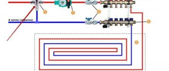
A more economical, but at the same time no less effective way to protect a solid fuel boiler from condensate is to regulate the temperature of the coolant entering the boiler using a thermostatic valve with a thermal head.
Connection and operation
Installation of a part on a heater does not require any special knowledge. You only need a set of wrenches to be able to tighten the valve, and a paste-sealant, with which you can "seal" the joints.
The connection of the three-way valve to the boiler is carried out according to the only possible scheme, so that nothing can be confused even with a special desire. It makes sense to hire a master only if the replacement is made under warranty, and you don't have to pay anything for it. Otherwise, you can do everything yourself within half an hour and save several hundred rubles.
The device described above clearly demonstrates that the unit consists of a minimum number of parts, which means it has high reliability. Malfunctions of the three-way valve of a gas boiler can only manifest itself in a violation of the tightness of the body or failure of the membrane. There is absolutely nothing more to break. Breakdowns are extremely rare and can be the result of a factory defect or improper use.
From an economic point of view, repairing the three-way boiler valve will be absolutely inexpedient. You can, of course, try to solder the leaky case, but soon a hole will form in it again, since this process is already irreversible.
At the same time, a new device can be bought for 500-700 rubles, replaced and for many years not to know about problems with this node. And it will be impossible to repair the inner membrane due to the difficulty of accessing the breakdown site.
Principle of operation
The valve protecting the boiler has a simple design and works according to a principle that is understandable even for a schoolchild. The instrument consists of a straight fitting with a 90 degree elbow and a spring-loaded, pressure-tight seal that closes off the side passage. When the pressure in the system increases from overheating, exceeding the clamping force of the spring holding the valve in a stationary position, it rises up and opens the side hole.
Excess liquid begins to pour out from the side and is sent to a container, drainage or sewer system. After venting part of the coolant, the pressure in the system and on the valve weakens, the spring puts it in place, blocking the side pipe.
Spring type constructive device