In technical systems, communications and many other similar structures, pressure drops often occur. The reasons for this may be different.
If a water supply system is considered, then excess pressure is formed there due to excessive accumulation of water and forcing it down the pipe. This happens due to several factors at once.
Air pressure is even more difficult. Here, an explosion can provoke a drop, a sharp decrease in the oxygen level in one of the adjacent rooms, etc.
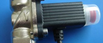
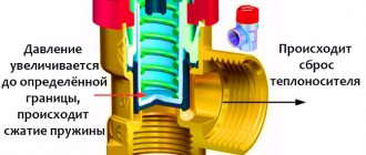
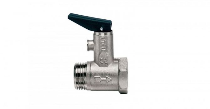
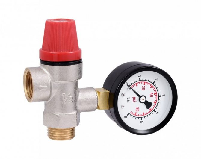
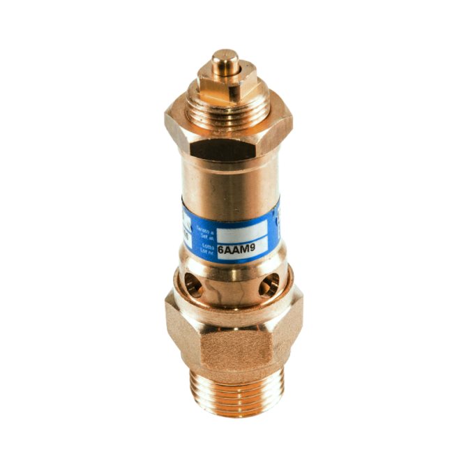
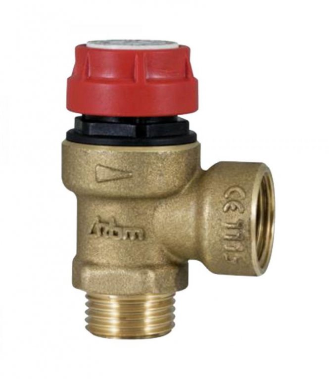
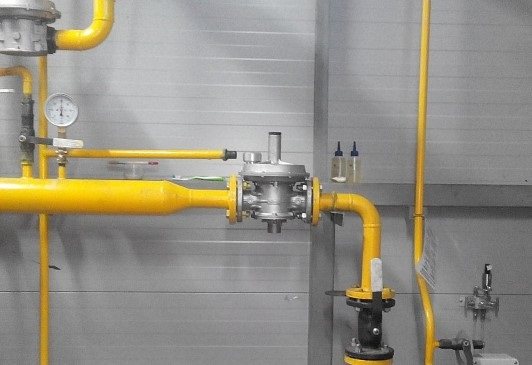
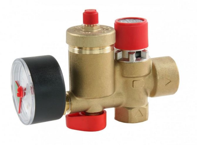
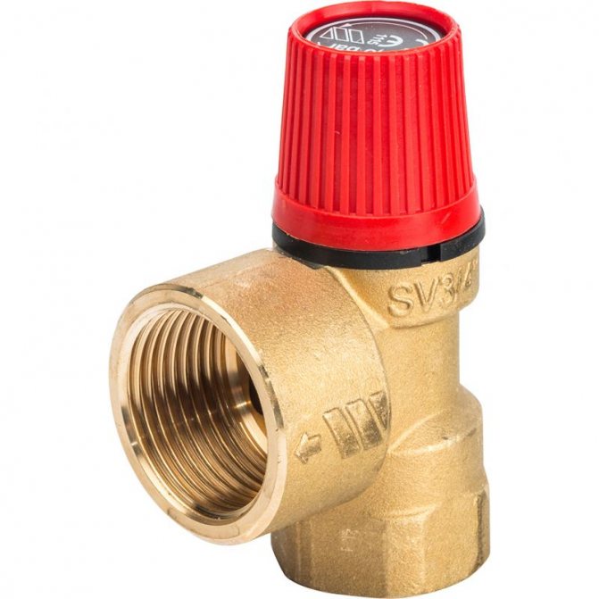
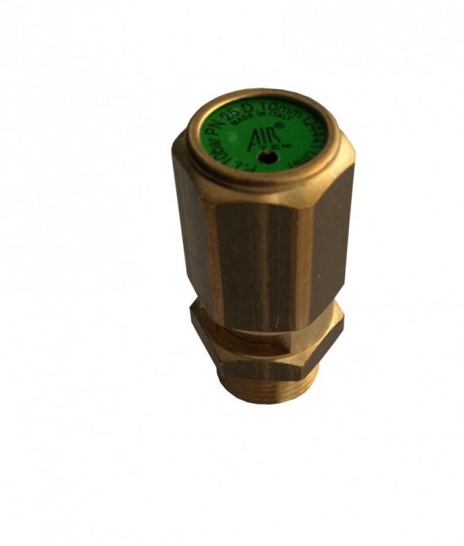
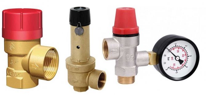
Pressure relief safety valve with pressure gauge
The consequences of such situations are unpredictable and rather dangerous. A pressure relief valve will help us prevent them from appearing. We will tell you about it now.
What is it and what is it for
This device is a special type of safety valves installed in pipeline systems to protect against destruction that occurs when overpressure in them.
Outwardly, it does not differ from bypass valves, which maintain a constant pressure in the system by continuously removing excess medium. But unlike them, it works in the system periodically, only at moments of pressure increase in excess of the established norm.
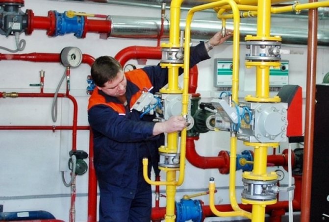
Purpose of the gas valve
PSK is a safety valve element responsible for the safety of a gas pipeline and gas equipment connected to it. During operation, the valve is in a closed position, therefore it is referred to as a closed pipe fitting.
Such devices are installed not only on gas pipelines, they are an integral part of other communications - water supply, heating network. Everywhere they perform the same function - they stabilize the pressure in the network, provide the operating parameters necessary for the correct functioning of the system.
The valve serves to dump excess gas if the pressure parameters become critical. Fuel that creates an imbalance in the system is discharged into an auxiliary pipeline or discharged into the atmosphere
The pressure surge is usually short-lived and depends on a number of factors.
Causes that can cause overpressure in the system:
- breakdown of connected gas equipment - double-circuit boiler, instantaneous water heater or storage tank, shut-off valves;
- use of fuel that is not suitable in composition;
- change in temperature indicators in the pipeline;
- failure in the thermomechanical circuit.
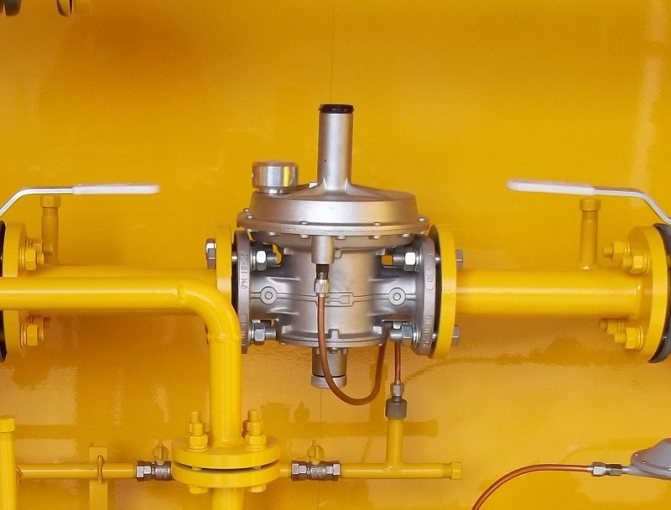
The installation location of the gas safety valve is standard, due to the effectiveness of the application: either in the pressure regulator, or immediately behind it. After the automatic actuation of the valve, it returns to the working - closed state.
In the gas network, the valve is a separate or integrated device in the pressure regulator. It is triggered if the working gas pressure exceeds the nominal level by 15%
What is the threat of the lack of the PUK in the network? The most common consequences are mechanical destruction of the pipeline or breakdown of connected equipment, which can cause gas leakage.
There is also a possibility of an explosion, therefore, it is necessary to constantly monitor the health of the device, to carry out maintenance on time and replace the failed elements.
Along with relief devices, gas safety shut-off valves are also used, with the help of which the fuel supply is shut off. This happens automatically. The shut-off valve element is installed on the pipeline, in the gap between the filter and the pressure regulator.
The slam-shut response limit is indicated in the technical passport of the device. The upper critical parameter is usually equal to the formula: slave. pressure + 25%.
Purpose and scope
The valve is used to protect premises and equipment from excessive pressure of the medium transported through pipes:
- heating systems - to remove from heating devices an excess volume of coolant formed due to thermal expansion;
- water supply - to reduce the risk of water hammer;
- ventilation - provides air movement only in a given direction;
- gas supply, compressed air supply, fire extinguishing and other types of pipeline structures - in case of emergencies.
Management and specifications
The simplest models of low-flow blast valves, used mainly for domestic engineering systems, are manually operated mechanically. Products installed on large production pipelines can be remotely controlled.
Depending on the material of manufacture, design features, devices are endowed with different technical characteristics.
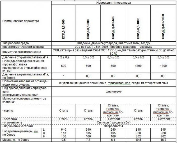
The characteristics of several models of emergency relief valves designed for service with gaseous substances are presented in the table.
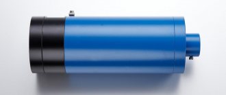
Overpressure valves
Normally closed fire damper overpressure
is intended for opening openings in the enclosing structures of vestibules and other rooms to maintain the required excess pressure from 20 to 150 Pa, as well as to compensate for the volumes of combustion products removed from rooms protected by exhaust smoke ventilation.
Compensating supply of external air by supply smoke ventilation with mechanical induction can be provided using air supply systems to vestibules or lift shafts. In this case, in the enclosures of the vestibule sluices, to which the protected premises are directly adjacent, overpressure valves in a fire-fighting design with the required fire resistance limits can be installed.
The use of valves is regulated by the Code of Rules SP 7.13130.2013 “Heating, ventilation and air conditioning. Fire safety requirements ".
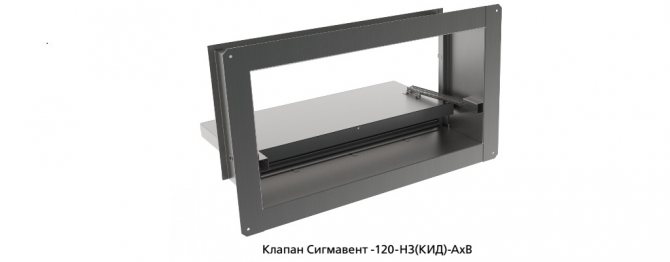
The valve is normally closed Sigmavent –120-NZ, fire resistance 120 min, and has a certificate of conformity to the “Technical Regulations on Fire Safety Requirements” (Federal Law No. 123-FZ of 22.07.2008).
The pressure drop across the closed door of the vestibule-sluice from 20 Pa to 150 Pa, as well as the return of the damper to the closed position when the pressure drops, is adjusted on the valve directly during testing of the anti-smoke system by adjusting the springs.
The valve size AxB (dimension A is parallel to the axis of rotation, dimension B is perpendicular to the axis of rotation) is a landing valve and corresponds to the opening in the enclosure of the vestibule. The standard valve body depth is 180 mm. The size of the opening can be from 150x150 mm to 1000x1000 mm with a step of 50 mm. It is possible to increase the size A up to 1500 mm while reducing the size B.
The size of the opening in the enclosing structure of the vestibule-sluice is determined by the designer, depending on the capacity and pressure of the smoke exhaust fans and the back pressure of the anti-smoke system.
To determine the area of the opening, a simplified formula is sufficient:
kpr.– coefficient taking into account the design features of the valve. For Sigmavent-120 NZ (KID) -AXV, it can be taken as 1.8. Vdv. - Air flow velocity in the open door with the valve closed, m / s. Sdv. - Open door area, m2 ΔРkid. - Pressure drop across the valve when the door is closed, corresponds to the excess pressure in the vestibule-sluice, Pa. ρw - Density of the supplied air, kg / m3
It is possible to manufacture overpressure valves with reverse flow for installation in the shaft wall. In this case, the depth of the body, subject to the requirement that the damper does not protrude beyond the front flange of the damper, is calculated.
Valve marking Sigmavent-120-NZ (KID) -AhV-Op
It is possible to manufacture overpressure valves in duct design with the marking Sigmavent-120-NZ (KIDK) -AхB with a body depth of 220 mm and with a reverse flow Sigmavent-120-NZ (KIDK) -AхV-Op with a calculated body depth.
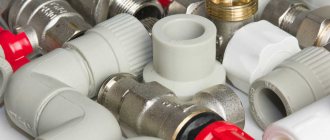
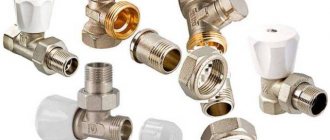
Connection type
By the type of connection or connection to the pipeline, the valves are divided into:
- flanged products - equipped with flange plates at each outlet and connected to the counter flanges at the ends of the pipes using bolts;
- threaded - imply the presence of outlet pipes with an external thread;
- welded - attached to the gas pipeline by welding and provide one hundred percent tightness.
Device
The standard design of the overpressure relief valve includes:
- cast body made of stainless steel, brass or bronze;
- plate - the main shut-off element that blocks the flow of the medium;
- poppet lever - used to control this part;
- safety lever - performs protective functions if the main blocking element did not work;
- adjustment knob;
- springs;
- additional details (buttons for control, counters, dials, barometer, etc.).
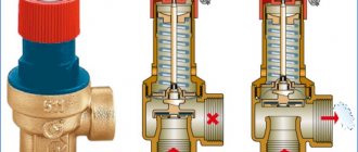
Types and designs
Relief valves are divided into two main groups:
- direct action, opening only under the influence of the pressure of the internal environment on it. These include devices used to prevent excessive pressure build-up in oil and fuel systems;
- indirect acting, using an external pressure source They are more suitable for liquid and air systems.
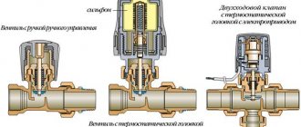
Depending on the design features and the principle of operation, they are divided into four types.
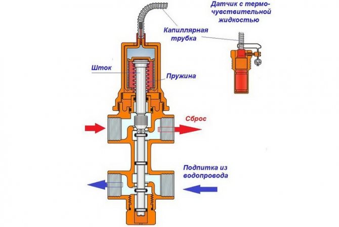
With remote sensor
The device is equipped with a spring mechanism and a rod driven by the main or reserve bellows. At the moment of water overheating, they are influenced by a thermosensitive liquid rising through a capillary tube from the sensor bulb.
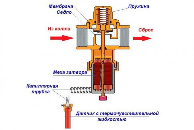
When the device is triggered, the stem opens the plate for the movement of the coolant. Two branch pipes are provided in the valve body to the supply line and to the sewerage system for discharging excess water.
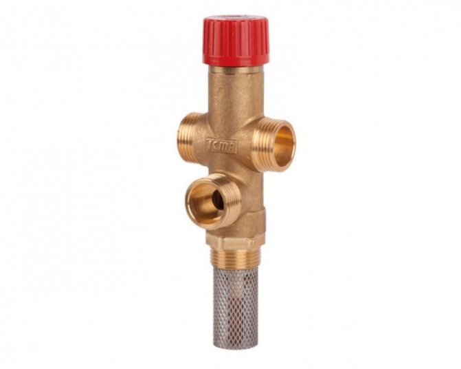
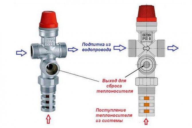
Combined systems with make-up
They are a type of safety valves in heating systems that can perform 3 functions at once:
- dump the overheated coolant from the boiler tank at the signal of the remote sensor;
- effectively cool the heat generator;
- automatically feed the heating system with cold water.
The stem of such a product is equipped with two plates that can simultaneously open 2 passages: one for dumping a boiling coolant, the other for supplying cold water.
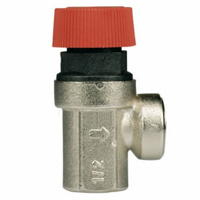
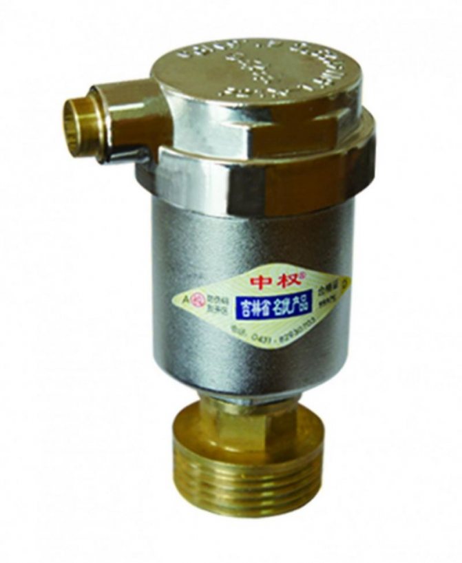
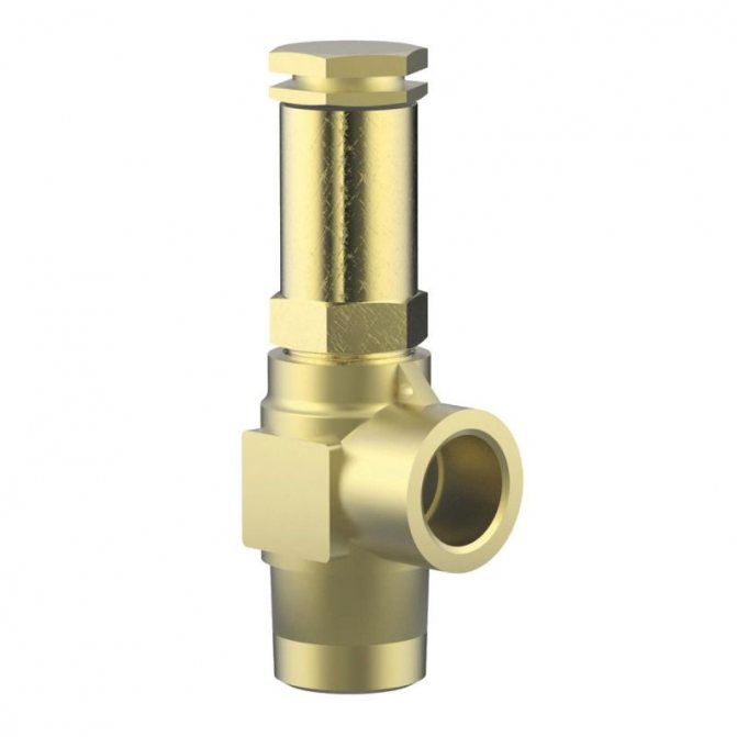
The models shown in the following photo have a triple outlet. They are built into the pipeline in front of the heater or boiler. To discharge the medium, the lower branch pipe is used, two upper branch pipes are intended for connecting the water supply and the make-up line.
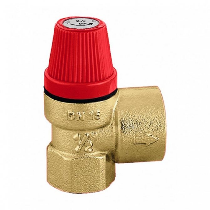
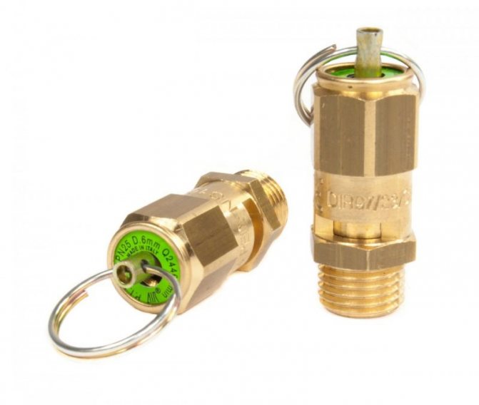
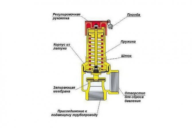
Spring loaded
In such devices, the spool is driven by the compression force of the working spring. The settings of the same valve can be adjusted by replacing the different types of spring that are included in the kit.
A number of models have an additionally mounted lever in the body, which carries out manual detonation. It can be used to manually purge the valve to check its general technical condition or to release part of the working medium.
Since the spring in most cases is under the influence of the internal working environment, then for devices that work with aggressive substances, it is covered with a protective polymer layer.Such product models have stem seals of the type of stuffing box or bellows device.
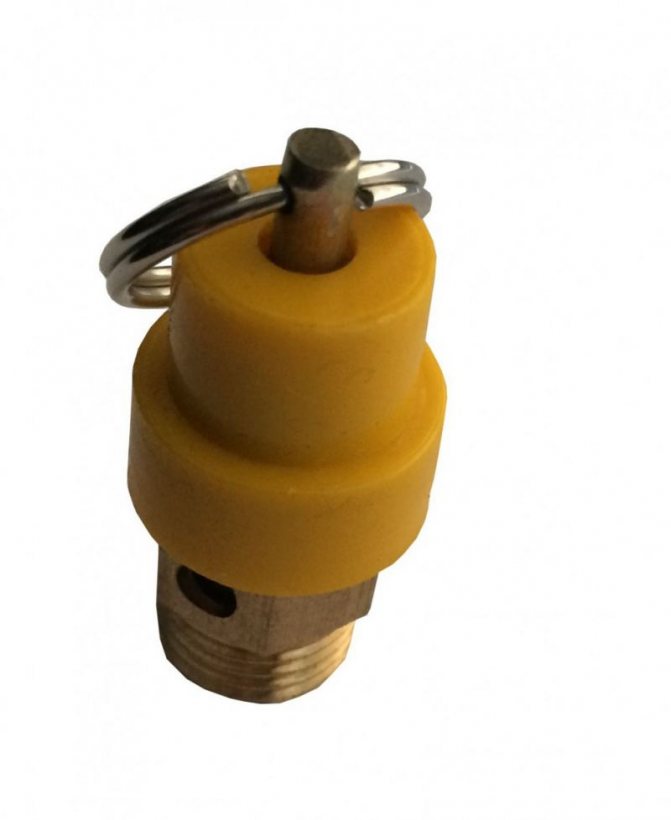
Lever-cargo
The main assembly of this type of valve mechanism is a lever with a weighting agent suspended from it. The actuation of the device is affected by the weight of the load and the length of the lever arm to the place where it is placed. The more massive it is and the farther it is from the stem, the higher the pressure the relief valve is triggered.
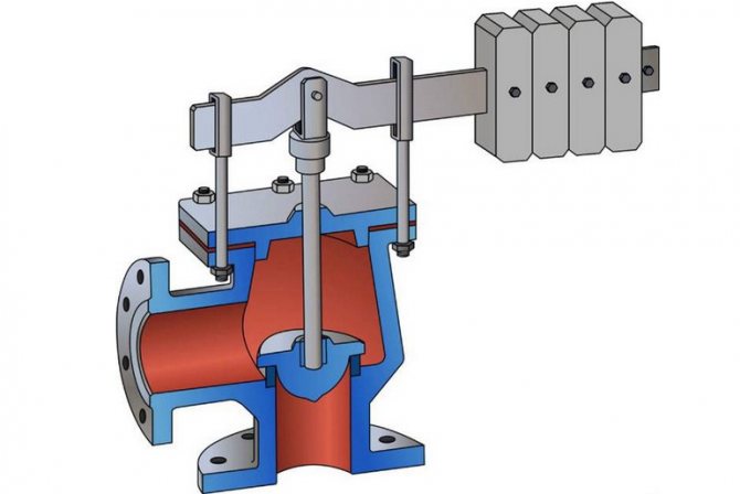
A heavier weight will be required to fully seal large saddles, and this can result in a fairly high level of vibration throughout the device. In such cases, valves are used in which the cross-section of the medium discharge is formed by two parallel seats. In the case of such a device, two gates are also installed, operating in parallel. This design reduces the weight of the weighting agent and the length of the levers and has a positive effect on increasing the rate of operation of the unit.
Features of the installation of the safety valve
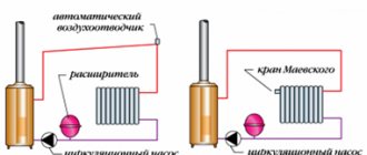
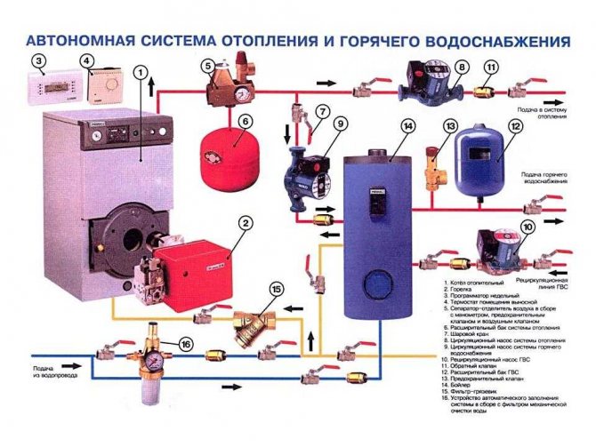
Heating circuit with installed safety valve
Professional installation of a safety valve in a heating system is to take into account not only its characteristics, but also the operation of the expansion tank. As soon as the latter cannot expand the internal volume of the pipes, the bypass valve should work and remove excess water from the pipes.
According to the rules, the relief safety valve for the heating system must be installed immediately after the outlet of the boiler (in the diagram, these are elements 3 and 4). The optimum distance between them is 20-30 cm. For visual control, a pressure gauge is mounted in front of it. According to its readings, you can determine the current state of the system.
There are certain rules for installing a safety valve in a heating system:
- Do not install shut-off equipment in front of the device and the boiler - valves, taps, etc.;
- To remove excess water, a drain pipe is installed at the outlet of the correctly selected heating safety valve. It can be connected to a return or sewer pipe;
- In a closed gravity system, the heating safety valve is installed at the highest point.
In addition, it is necessary to periodically check the condition of the mechanism. Spring models are characterized by "sticking" of the plate to the walls of the body. This increases the maximum opening pressure of the safety valve in the heating system. As a result, if the permissible pressure value is exceeded, the device will not work.
To a greater extent, the latter relates to the operating conditions of the safety valve for heating than to the principle of its operation. However, without this, even with a perfectly executed installation, the likelihood of incorrect operation of the device increases.
If the number of emergency descents was 7-8 times, experts recommend replacing the valve. This is due to the natural wear and tear of the spring and disc.
What should be considered when selecting a safety valve for an autonomous heating system? Compliance of its technical characteristics with operational ones. It is also important to properly connect it to the pipe. The best way to do this is to use a traditional pipe tow. The FUM tape may not withstand the temperature effect, as a result of which a leak will appear.
For a better understanding of the principle of operation of the safety valve, it is recommended to watch a video about the design and operation of the spring model:
Advantages and disadvantages
The use of overpressure relief valves allows you to extend the life of pipelines by eliminating the occurrence of water hammer and relieving pressure in the system when it rises to critical values. The advantage of these devices is also:
- simplicity and reliability of the design;
- not complicated installation and further maintenance of the device;
- low values of local resistances;
- high throughput.
The disadvantages include conditionally:
- low wear resistance of gaskets, ensuring tightness on the stem;
- unsuitable for work with media containing solid particles.
Purpose and place of installation
Closed-type heating systems operate at a certain pressure. Significant increases in operating pressure will lead to equipment failure. Connections may leak, plastic parts and elements may burst. In the most unfavorable situations, the boiler heat exchanger can explode. This is already very dangerous and threatens not only the floor flooded with hot coolant, but also burns. After all, the temperature is serious.
Protect the heating system from excessive high pressure and there must be an overpressure relief valve. While the parameters of the system are within the normal range, it does not manifest itself in any way. Although the pressure in the system gradually increases from the moment the boiler is started, it is compensated by the expansion tank, maintaining a stable state of the system. But he may not do this indefinitely, although, with the correct calculation, he is enough for regular situations. If the expander fails, the pressure starts to build up. When it exceeds the threshold, the overpressure relief valve is triggered here. It simply releases some of the coolant, thereby stabilizing the emergency.
That is, the overpressure relief valve in the heating system works in emergency situations. Therefore, it is also called "emergency". And also - "discharge", "drain", "protective" and "subversive". These are all names for the same device.
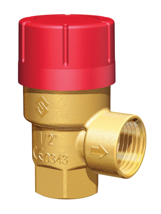
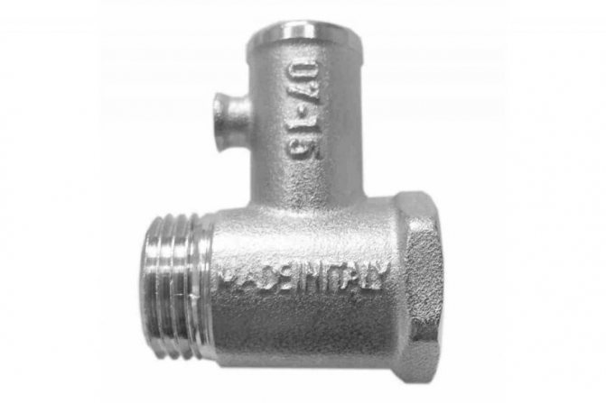
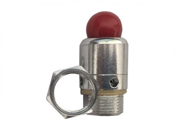
What does a safety (emergency) valve for heating look like?
As is clear from the description, when the pressure rises above a certain limit, a certain amount of heat carrier is simply released from the system. If you came to the boiler room, and a puddle formed under the emergency valve, it means that there was an abnormal situation during which the pressure increased. There is no other alarm. So these traces are worth paying attention to. It is worth immediately checking the operability of the valve itself and the membrane tank. Most likely, the reason is in them. If you do not pay attention to these symptoms, after a while you may run into problems: either something will "fly" in the system, or it will rupture the hot water boiler.
The installation location of the heating emergency valve is on the supply pipe, not far from the boiler
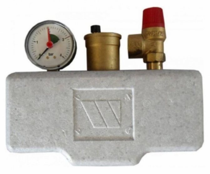
Of all the equipment for an individual heating system, the most dangerous is the boiler. Therefore, an overpressure relief valve is installed either directly on the boiler itself (if there is an appropriate outlet for the installation) or on the supply line immediately after the boiler. The distance is small - 20-30 cm from the body. If the boiler does not have this type of fittings (indicated in the description), then it is installed in the so-called safety group or separately. The safety group is placed on the outlet from the supply line immediately after the boiler (before the first branch and any other device), on which a pressure gauge, an automatic air vent and an overpressure relief valve are installed.
Selection Tips
When choosing a device, you must focus on:
- its compliance with the maximum allowable pressure in the system;
- section of the pipeline;
- medium temperature;
- throughput and height to which the spool is able to rise;
- type of working substance.
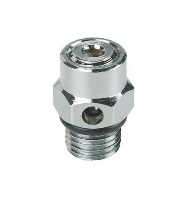
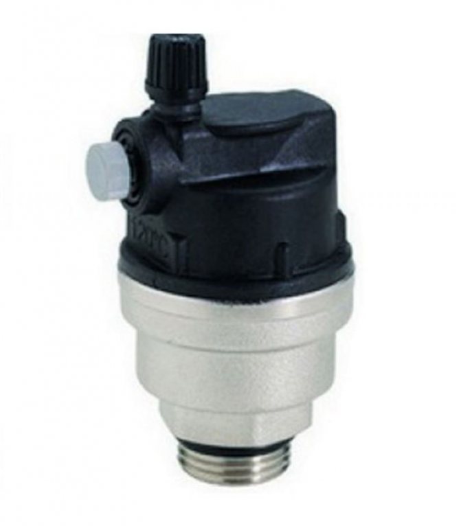
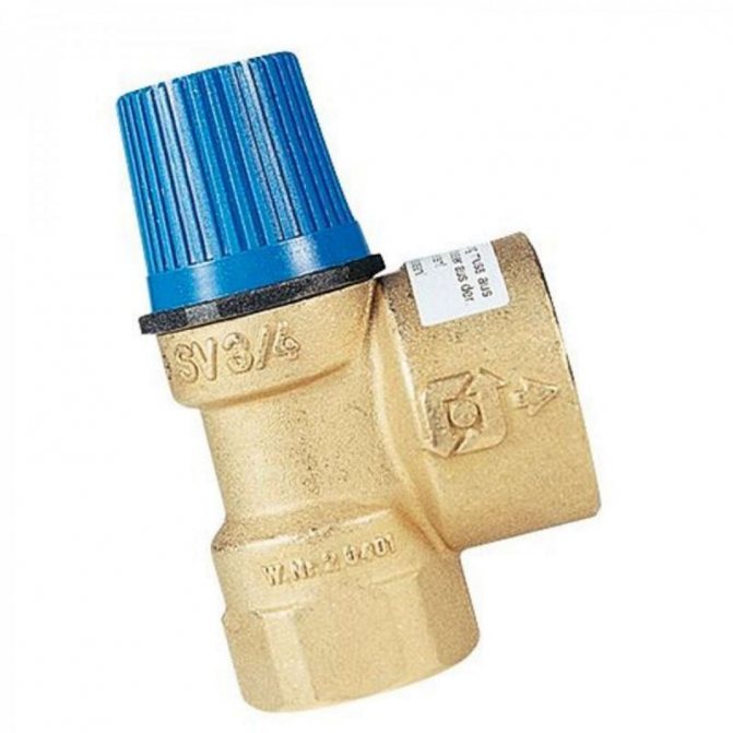
If it is intended to discharge the working medium directly into the air, then a valve with an open type design can be used. For liquid systems, a closed-type device is required, preferably with a special spout for connecting the discharge water discharge hose. On the body of the product, markings of the direction of flow of the medium should be applied, which will greatly facilitate the installation work.
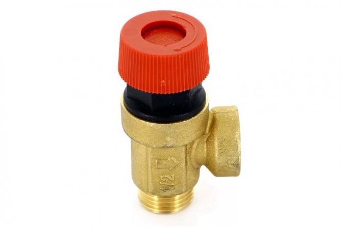
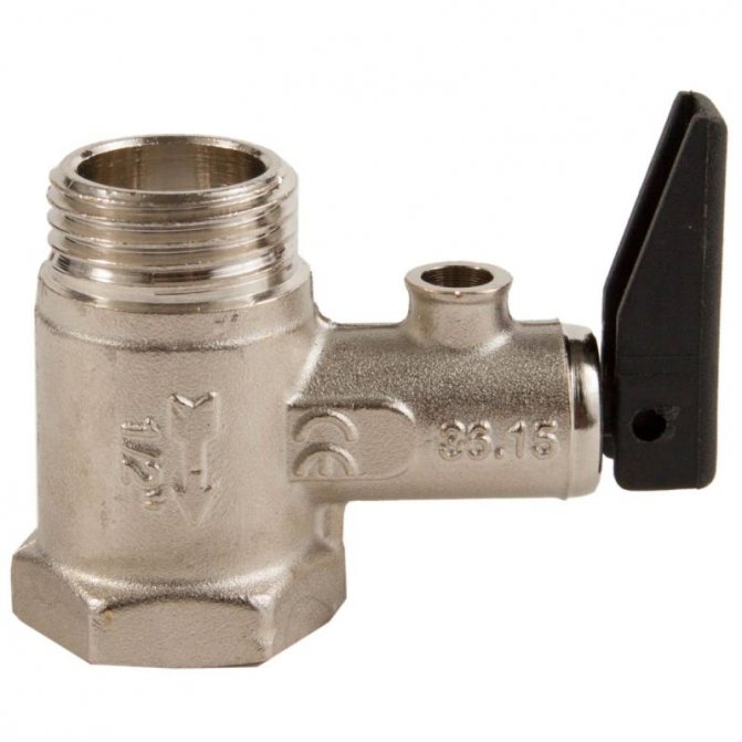
Safety valve types:
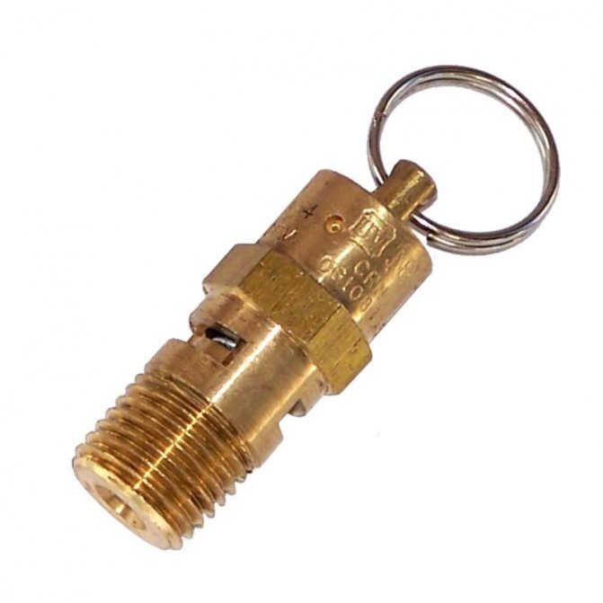
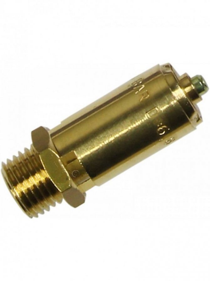
- Coupling fuses made of brass. This view is straight-through, that is, it opens by pressure. This is a cheap option, but reliable enough. And it has a simple design: a thread on both sides, and a stem with a gasket.
- More complex brass fuse. Install such a valve in the heating system after the circulation pump. The spring and stem in this design are made of stainless steel. This safety device can withstand temperatures up to 1200C.
- Check valves are a type of safety device that should not allow a backflow of the coolant in the heating system if pressure drops there.
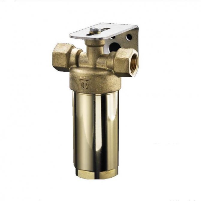
Instrument installation and operation rules
Installation of the product on the pipeline should be done with gaskets without distortions. The composition of the working substance passing through the valve must be free of mechanical inclusions and abrasive particles. It is advisable to install a strainer of the appropriate diameter at the inlet to the system. The installation of the device with a spring mechanism is carried out strictly in a vertical position, with the lid up. For the lever included in the design of the lever-loading device, it is necessary to provide a horizontal position. It is not recommended to place shut-off elements in the form of taps, gate valves, levers in front of the relief valve.
To eliminate excess liquid, it is necessary to provide for the installation of an additional outlet used to drain water into the sewer pipeline or reverse-acting pipe.
If the system includes a gravity device, then the valve must be installed at the highest point.
During operation, it is necessary to periodically revise the device, since in products with a spring mechanism, the plate may move to the walls of the case.
Required tools and materials
To install the valve you will need:
- adjustable wrench;
- fum - tape or tow;
- special paste for sealing joints.
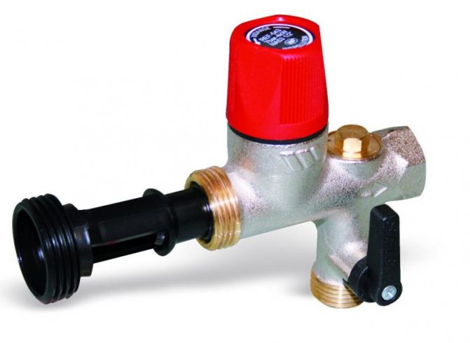
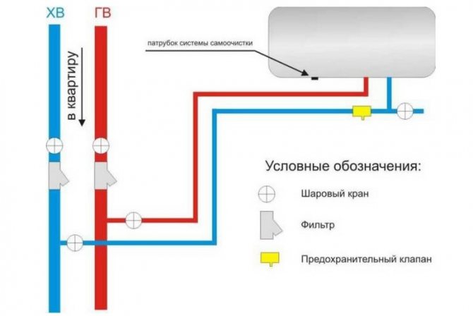
Connection diagram
For example, consider the installation diagram of the device in front of the hot water heater in the apartment.
Work progress
Each product designed to release overpressure is complete with installation instructions, which should be carefully read before starting work. Before installation, you also need to disconnect the water heater from the network and drain the water from it. The valve should be placed on the cold water supply up to the stopcock. The valve installation sequence is as follows:
- marking of the installation site;
- removal of a part of the pipe with a size corresponding to the length of the device body;
- threading at the ends of pipes:
- covering the threaded part with tow or fum tape;
- screwing the valve onto the pipe thread;
- connecting to another pipe a tube leading to the sewer system.
- tightening the threaded connection with an adjustable wrench;
- sealing the junction with a special paste;
- setting up the device in accordance with the passport values (if necessary).
Specifications
| Parameter name | KSID-P-0.5- 600 | KSID-P-0.5- 600 (T) | KSID-P-1,2- 600 | KSID-P-1,2- 600 (T) | KSID-P-0.5-100 | KSID-P-0.5- 1200 (T) | KSID- P-1,2- 1200 | KSID- P-1,2- 1200 (T) | KSID-P-0.5- 1800 | KSID-P-0.5- 1800 (T) |
| Working environment type | Freons, carbon dioxide, inert gases, air | |||||||||
| Shutter tightness | class "C" according to GOST 9544-2005. Test substance - "water" | |||||||||
| Climatic performance | UHL, placement category 2 in accordance with GOST 15150, but for temperatures from minus 60 to plus 80 С | |||||||||
| Valve opening pressure *, kPa | 0,5 ± 0,2 | 0,5 ± 0,2 | 1,2 10,2 | 1,2 ± 0,2 | 0,5 ± 0,2 | 0,5 ± 0,2 | 1,2 ± 0,2 | 1,2 ± 0,2 | 0,5 ± 0,2 | 0,5 ± 0,2 |
| Flow area (opening) of the valve with a fully open damper, cm2 | 600 | 600 | 600 | 600 | 1200 | 1200 | 1200 | 1200 | 1800 | 1800 |
| Valve closing pressure **, kPa, no more | 0,3 | 0,3 | 1 | 1 | 0,3 | 0,3 | 1 | 1 | 0,3 | 0,3 |
| Valve position on enclosing structures | inside the protected area, horizontal, inlet downward | |||||||||
| Type of connection to the building envelope | Flanged | |||||||||
| Material of the main valve elements: - body | Steel | Insulated steel | Steel | Insulated steel | Steel | Insulated steel | Steel | Insulated steel | Steel | Insulated steel |
| - shutter | Steel | Textolite | Steel | Textolite | Steel | Textolite | Steel | Textolite | Steel | Textolite |
| - sealant | Silicone (profile "D") | |||||||||
| - damper bearing | Brass | |||||||||
| Overall dimensions, mm, no more: -length; | 662 | 662 | 662 | 662 | 760 | 760 | 760 | 760 | 858 | 858 |
| - height; | 160 | 160 | 160 | 160 | 225 | 225 | 225 | 225 | 290 | 290 |
| - width | 150 | 150 | 150 | 150 | 240 | 240 | 240 | 240 | 300 | 300 |
| Weight, kg, no more | 6,4 | 7,7 | 9,5 | 10,8 | 13,5 | 13,7 | 15,3 | 15,5 | 17,8 | 18,3 |
| The opening pressure of KSID-P is determined from the condition of maintaining the strength of the building structures of the protected premises or the equipment located in it. Note: * Opening pressure is the excess gas pressure before the valve, at which the shut-off element begins to rise above the seat. ** Closing pressure - excess gas pressure by the valve, at which, after the medium is released, the shut-off element is seated on the seat with the specified tightness. | ||||||||||
Expert advice
- The blasting device with standard specifications allows water to pass through even at low pressure levels when clogged. You can solve the problem by cleaning the body parts. For this, the product must be dismantled and placed in a container with vinegar for 2 - 3 hours. Then rinse it with water until it is completely clean and reinstall it, lubricating the connection area with alcohol.
- If the valve continues to leak after cleaning, then most likely the rubber gasket resting on the seat is clogged with debris. It is easier to replace such a part than to clean it without deformation. The replacement of the valve on the supply line to the boiler can be seen in the video:
- A number of consumers quite reasonably doubt the durability of valves with plastic parts. They really have a shorter lifespan, so it is better to buy straight away with metal components. Such products are on average 100 - 150 rubles more expensive, but they last much longer.
- You cannot simply drown the device, even if it leaks. A huge number of heating boilers failed just after the plug was installed.