0
18529
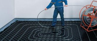
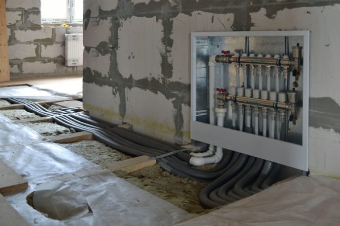
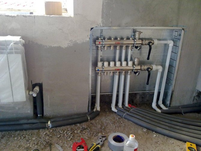
The installation of the water floor covering starts from the walls, where the place for the collector is prepared. First of all, a recess is made in the surface of the wall, where it is planned to place the collector cabinet for the device. It creates a convenient system connection and practical use. It is often installed in boiler rooms or rooms where the heated floor itself is located.
general information
Almost every heating system cannot be imagined without a heating distribution cabinet. Its installation solves several problems at once.
Compared to the do-it-yourself piping, the manifold wiring is much more efficient and practical, and it looks very aesthetically pleasing in a special cabinet. The manifold cabinet for heating can accommodate both a meter and electrical equipment.
Here are some points to prove that the switch cabinet is indispensable:
- in it you can hide the collector itself from the eyes;
- there the connection of the underfloor heating system pipes with the entire heat supply system is carried out;
- this is a place for mounting other connections and measuring instruments.
A manifold cabinet for a warm floor is designed to hide and protect expensive engineering units from interference from the outside.
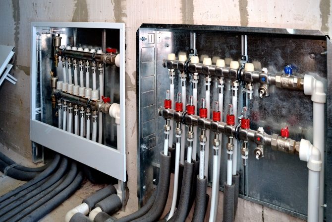
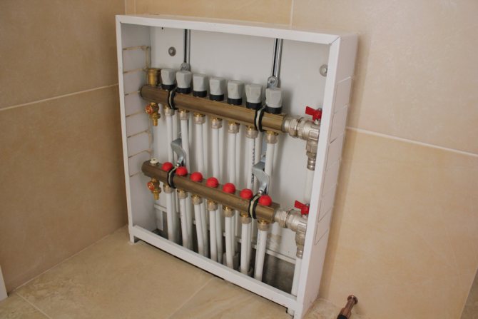
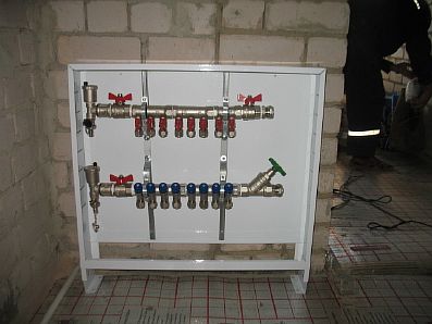
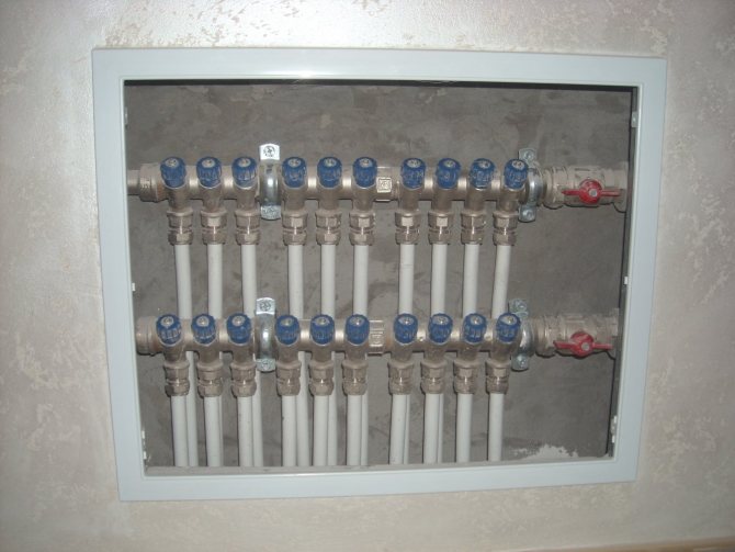
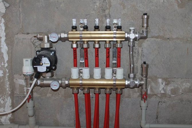
Manifold cabinet mounted
Assembly and installation
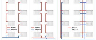
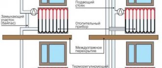
It is recommended to install a cabinet with a manifold block so that the underfloor heating loops are approximately the same length. If the distributor is located above the level of the heating circuit, air from the system will be automatically removed through the air vent. In the case when the cabinet is planned to be hidden in the basement or placed on the floor below, it will be necessary to put on each circuit an air vent complete with a ball shut-off valve, as well as on the return line.
When assembling the manifold block, pay attention to the tightness of the connections. If there are no rubber O-rings included with the equipment, the thread is sealed with a winding.
Next, the underfloor heating collector is installed in a special cabinet. The guides, equipped with bolts and nuts for fastening the dies, move according to their length. If the manifold block is mounted without a cabinet, clamps with dowels or brackets are used. At the same stage, if necessary, a mixing unit is mounted, a circulation pump for a warm floor is installed. In conclusion, the circuits are connected, the system is pressurized.
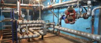
System elements
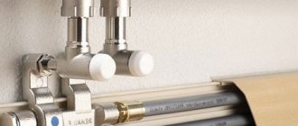
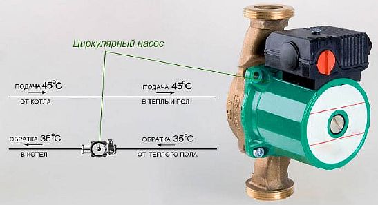
After connecting the cabinet, the supply and return pipes are mounted. Hot water flows from the boiler along the supply circuit. The liquid cooled down during heating flows back to the heating source.
The circulation of the coolant is due to the pump. A shut-off valve is installed in the cabinet on each pipeline. If necessary, remove several elements from the system (during repair work or if you want to save money), this does not affect heating in the rest of the house. You just need to turn off two taps.
Compression fittings will help if you need to join a plastic pipe and a metal valve.
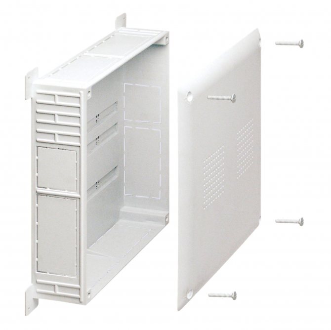
The main components of the cabinet:
- The body is a box that consists of stainless steel or durable plastic.
- Fastening system (depends on how the structure will be located, on the surface or in the middle of the wall).
- Often spacers or anchors are used as fasteners. Some cabinets have brackets and adjustable clamps.
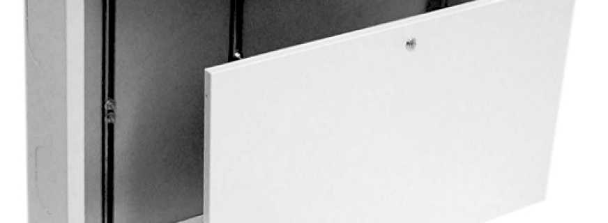
- The door is its function in protecting the content from unnecessary external interference. It is fastened with hinges, has a lock or a latch.Popular design colors are white, beige, less often other shades.
The manifold cabinet is not difficult to do with your own hands. However, it is not so expensive in specialized stores to waste time on its creation.
You can find out more about the collector for underfloor heating here.
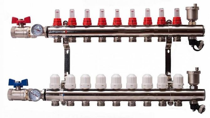
Manifold assembly
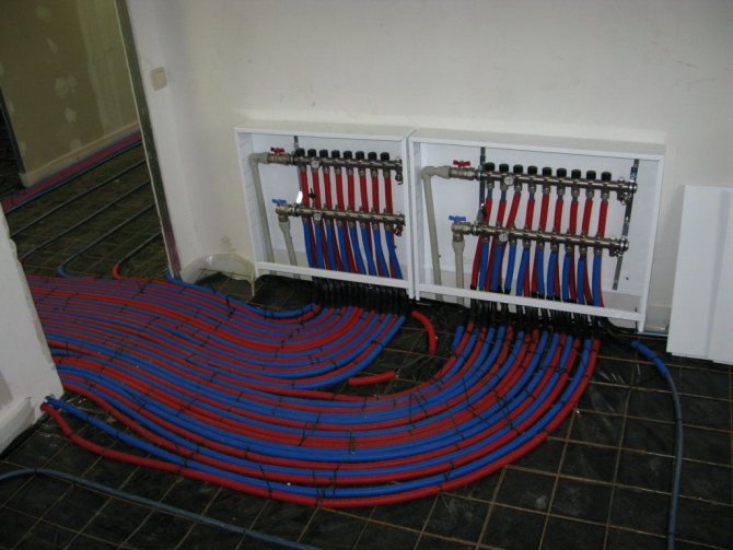
The collector for a water underfloor heating is installed based on the location of the main pipelines of the boiler and the corresponding configuration of pipelines for individual rooms. Typically, the underfloor heating unit is installed in a wall space, which is exactly removed from the end branches of heat pipes to the longest points. This is necessary for optimal hydraulic operation of the entire underfloor heating system. If you have a large number of rooms that are going to be heated using a water-heated floor, it is better to provide several units for separating the coolant at once.
Manifold assembly
Advantages of a distribution cabinet
A manifold cabinet for heating is a practical and necessary thing for the following reasons:
- Its use makes it possible to reduce the number of pipes required to connect a warm floor. The pipes do not need to be pulled from the heater, as the collector can be placed in the same room.
- In addition to the collector mounting, the cabinet can also be for water supply, a liquid meter is installed in it.
- When repairing and modernizing the heating system, you can easily access the guide loop.
- Safety is one of the most important points. A door with a key will help protect the collector cabinet with expensive components from children.
Manufacturing materials
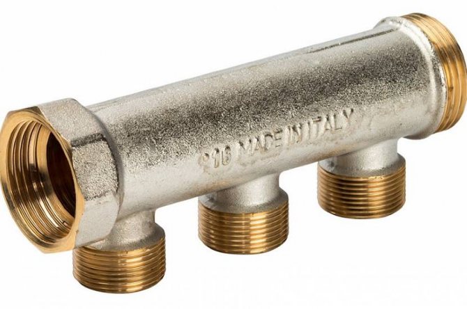
The reliability and durability of the collector directly depends on the material from which it is made. A comb for a warm floor can be metal or polymer. Each of the options has its own advantages and disadvantages.
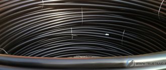
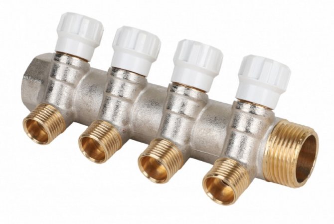
Polypropylene
A manifold made of polypropylene pipe is an extremely economical option. In addition to the affordable price, the device's low weight can be noted. Models with fittings and combs with shut-off ball valves are on sale. To connect metal products, combined fittings are used.
The disadvantages of polypropylene collectors include:
- thick walls, due to which the cross-section of the passage is smaller than that of combs made of metal of the same size;
- less strength and durability compared to metal models;
- oxygen permeability - even if polypropylene is reinforced by fiberglass reinforcement, oxygen diffusion is present, which provokes corrosion of the steel elements of the heating system and the boiler.
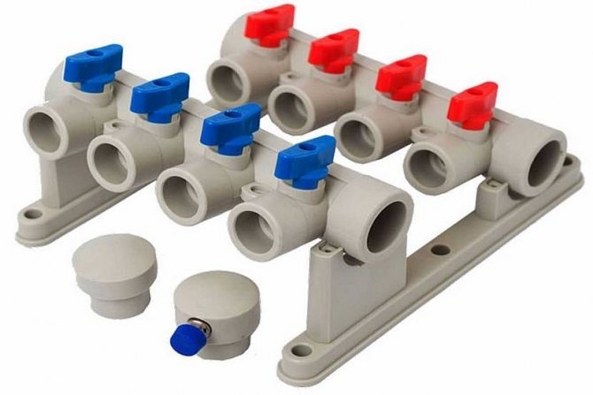
Polypropylene manifold block Source chudopol.ru
Cabinet types
There are two types of heating distribution cabinets:
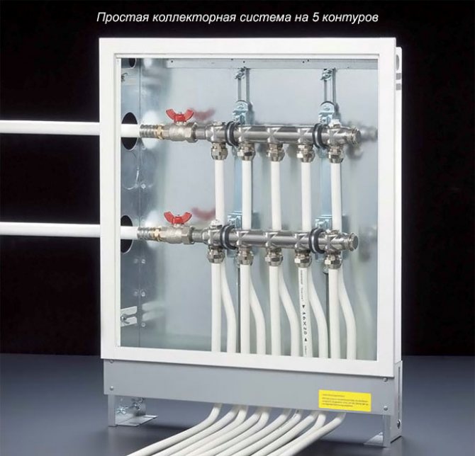
- Built-in manifold cabinet - installed in the wall itself or hidden under the plasterboard cladding. As a rule, such models have unpainted sides, because they contain outlet and fixing spans. Often the structure is 120 mm deep, 465 to 1900 mm wide, and about 650 mm high. To simplify the designations on the niche and to arrange collectors of different sizes in the cabinet, certain designs have retractable legs (they allow the cabinet to be raised up to 100 mm in height).
Recessed manifold cabinet - Outdoor models are easy to install and wall mount. The side walls of the structure are coated with a special anti-corrosion agent or powder paint. The outlet holes are first covered with easily removable metal strips. The external heating manifold cabinet is almost identical to the dimensions of the built-in structures. Legs are also present.
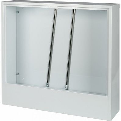
External metal collector cabinet Wester SHRN-5
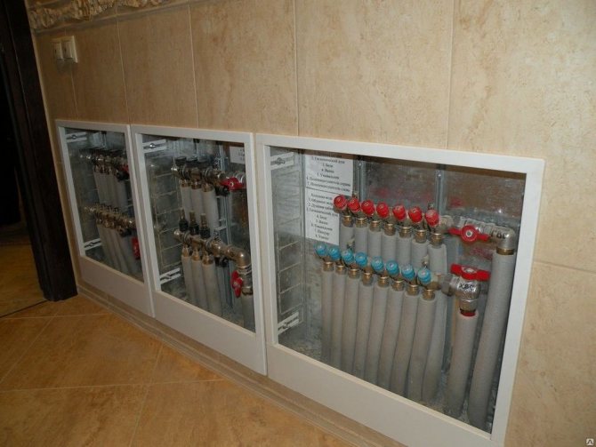
It is the built-in distribution cabinets that are more in demand on the market, since they are not so noticeable to the eye, fit well into the interior of the premises and are practical in operation.
Installation of the underfloor heating collector
Having collected the main elements, you can proceed to the installation and connection of the underfloor heating collector. The process consists of several steps:
- Location and location of installation. The standard height of the collector mounting on the wall from the base of the floor is 500 - 1000 mm, it should not be installed below, since it will be difficult to connect the floor pipes to it. In addition, it should be placed so that the lengths of all loops are the same, and there should be free access to it, preferably in the middle of the room.
- Installing a manifold cabinet. At the planned site, a collector cabinet is being installed, usually its size is 1 by 1 m, with a wall thickness of 12 cm. It can be placed in an equipped niche or fixed directly on the wall. The surface of the wall must be flat, otherwise the structure may malfunction.
- Fastening the comb in the box. The cabinet is equipped with special guides, they can be moved to the required distance, it depends on the length of the collector. They have fasteners - bolts, with the help of which the device is fixed in the box.
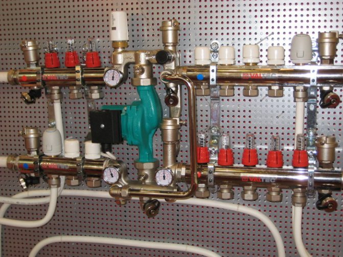
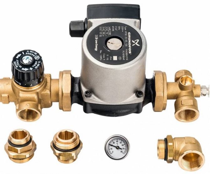
- Installation of the pump and valves (two or three-way) is carried out according to the planned scheme. On the supply pipe that goes from the boiler, a valve with a thermal head is first mounted, then the pump is installed on flanges with union nuts, it must be placed between the valve and the manifold. It is impossible to install the pump in front of the shut-off valves, then the valve will not function, and the water will not flow correctly.
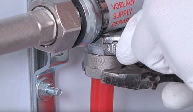
Connecting the TP to the collector
It is necessary to connect the contours of the underfloor heating to the outlets of the comb using a threaded connection under the Eurocone. More often, the Eurocone has a diameter of 17 mm, while the floor hose is 16 mm. Therefore, you will need to calibrate it for this size. Then:
- it is necessary to put the union nut on the tube, insert the compression ring and the thrust sleeve;
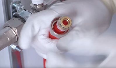
- manually connect the end of the hose to the comb fitting;
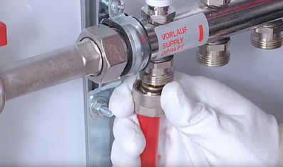
- finally tighten with two wrenches - one fixes the hexagon on the fitting, the other tightens the connection.
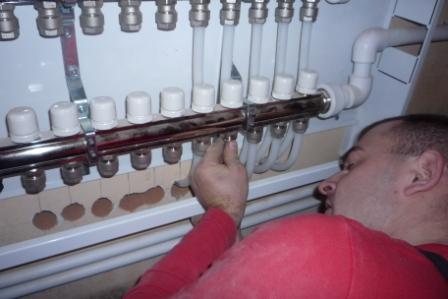
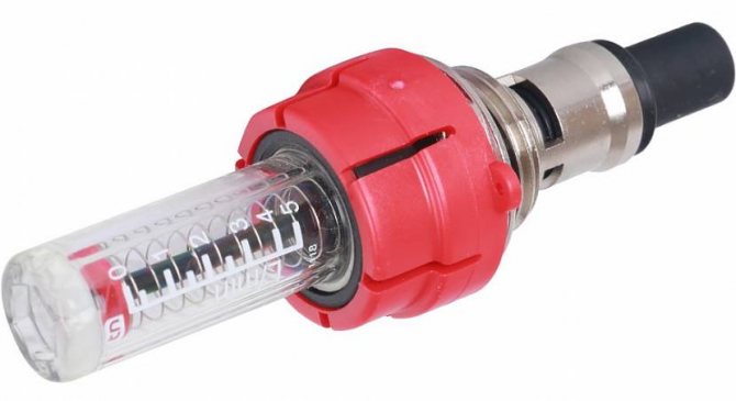
Collector setup
The process of setting up a collector for a water underfloor heating is done according to the following instructions:
- removing the cap from the valves;
- fixing the valve with a hexagon;
- determination of the number of revolutions for a specific loop;
- scrolling the valve by the calculated number of times.
The rest of the underfloor heating contours can be adjusted as well.
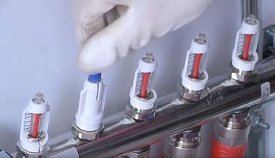
The service life and quality of the floor depends on how accurately the setting is made.
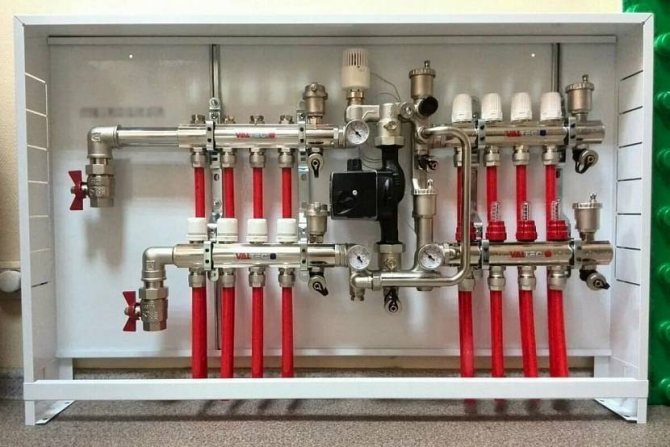
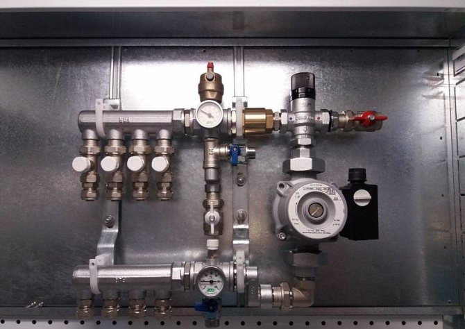
Cabinet Installation Recommendations
The collector is placed in a box, the structure is attached to the wall in a recess. In the middle there are vertical strips that fit the width of the main unit. On it, the circuits and other elements of the thermal supply of rooms are connected, and other elements are installed.
The underfloor heating collector cabinet is connected taking into account the increase in the floor by the point of the thickness of its layers.
After fixing it, a hot coolant and a return circuit are carried out. The supply pipe is for warm liquid coming from the heating boiler, the return pipe is for cold one.
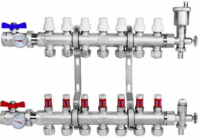
Why do you need a collector
In fact, the collector is a pipe with holes for the inlet and outlet of the coolant, it is also called a distribution and mixing unit. The function of the device is to maintain the required temperature level in the system and control the water flow.
The device is designed to mix the water coming from the boiler, where it is heated, with the cooled liquid coming from the return, to the required level for underfloor heating. Indeed, in a boiler, the coolant usually warms up to +90 degrees, and for a heated floor it is a high temperature.
It requires +40 - 45 degrees, so you can't do without a collector. If water flows directly from the heat source into the circuits, this will lead to overheating of the system and its failure.
In addition, the circuits have different lengths, and they have different heat energy requirements. Therefore, a special unit is needed between the boiler and the pipeline, which will distribute the flows of hot water along the loops.
How collector boxes are attached
There are two mounting options, depending on the type of installation, for distribution cabinets.
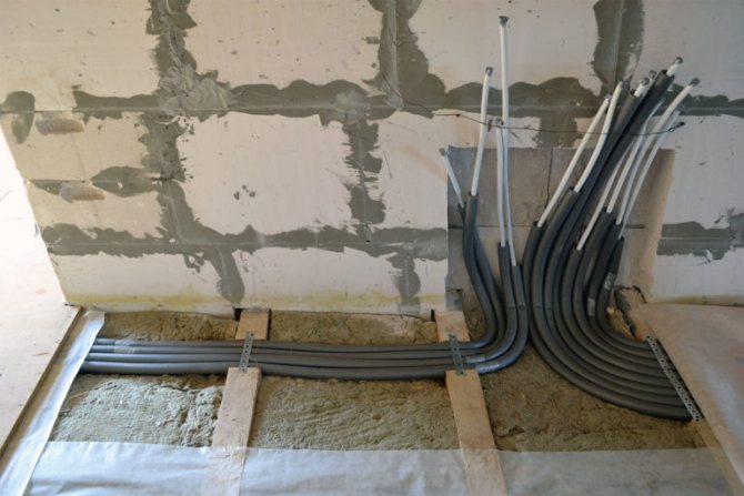
For embedded
Difficulties should not arise when the niche has already been provided for during construction work. When planning an underfloor heating system and installing a cabinet:
- Places for the collector are selected, should be collected above the floor level, since difficulties with heat supply are not excluded.
- Make wall markings for pipelines.
- With the help of a chasing cutter, holes are made for a box, pipes.
- A distribution structure is inserted into the recess of the wall, interconnected with anchors on the sides of the cabinet.
- The collector is mounted, the circuits and heat supply are connected.
- The space between the cabinet and the wall covering is covered with mortar and putty.
For outdoor
Installation may seem easier to some:
- A place for placement is selected.
- There is a wardrobe.
- Aligns with drawing marks.
- Using a perforator, holes are made for anchors, the cabinet is screwed on with screws.
- A collector is installed, circuits are connected.
- The wall remains the same, the cladding does not need to be touched.
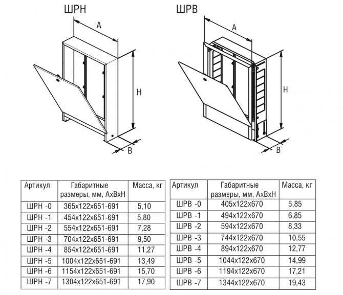
What are the sizes of boxes and options in demand
As a rule, constructions of the Grotto (Russia), Valtek (Italy), Vester (Russia) brands are most often bought. The sizes of the cabinets are different (see tables).
Dimensions of built-in manifold cabinets.
| Designation | Dimensions (edit) | Manufacturer |
| ShV-1 | 670×125×494 | Grota |
| ShV-1 | 648-711×120-180×450 | Wester |
| ShV-2 | 670×124×594 | Grota |
| ShV-2 | 648-711×120-180×550 | Wester |
| ShV-3 | 670×125×744 | Grota |
| ShV-3 | 648-711×120-180×700 | Wester |
| ShV-4 | 670×125×894 | Grota |
| ShV-4 | 648-711×120-180×850 | Wester |
| ShV-5 | 670×125×1044 | Grota |
| ShV-5 | 648-711×120-180×1000 | Wester |
| ShV-6 | 670×125×1194 | Grota |
| ShV-6 | 648-711×120-180×1150 | Wester |
| ShV-7 | 670×125×1344 | Grota |
Dimensions of external manifold cabinets.
| Designation | Dimensions (edit) | Manufacturer |
| SHN-1 | 651-691×120×454 | Grota |
| SHN-1 | 652-715×118×450 | Wester |
| SHN-2 | 651-691×120×554 | Grota |
| SHN-2 | 652-715×118×550 | Wester |
| SHN-3 | 651-691×120×704 | Grota |
| SHN-3 | 652-715×118×697 | Wester |
| SHN-4 | 651-691×120×854 | Grota |
| SHN-4 | 652-715×118×848 | Wester |
| SHN-5 | 651-691×120×1004 | Grota |
| SHN-5 | 652-715×118×998 | Wester |
| SHN-6 | 651-691×120×1154 | Grota |
| SHN-6 | 652-715×118×1147 | Wester |
| SHN-7 | 651-691×120×1304 | Grota |
| Shn-7 | 652-715×118×1300 | Wester |
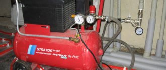
After the system is installed, the branches are adjusted, it is required to perform a start-up, heating the heating structure in order to identify problems at an early date. In addition, experts advise specifically to create a working pressure in the system about 25% higher than during normal use, and pay attention to the tightness of the joints.
Briefly about the main
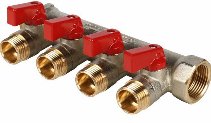
The equipment of the manifold block must meet the requirements for the functionality of the system. The collector device ensures uniform heating of heating elements and a constant room temperature. Manufactured from the following materials: polypropylene, brass and steel.
The manifold consists of a system to which threaded elements, fittings or control valves are connected. The collector is mounted in a special cabinet or brackets are used.
Along with it, a mixing unit is used.
The durability of the combs directly depends on the material and workmanship. You can purchase a ready-made complete distribution block or assemble it yourself from separate elements.
Ratings 0