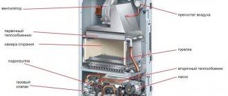

Principle of operation
The principle of operation of the burners is to pre-mix the fuel with air, ensure the supply of this mixture for combustion and make sure that the combustion products go through the combustion process completely.
The work of this device is divided into three stages:
- Preparation... At this stage, the preparation of individual elements of the future combustible mixture is carried out. At the time of the preparatory stage, the air and fuel are given the necessary characteristics: direction, temperature, speed.
- Mixing... Air and the required amount of fuel are mixed, resulting in a mixture of a combustible nature.
- Combustion... At the final stage of the burner operation, the combustion process occurs, or rather, the oxidation reaction of the elements of the combustible action with the help of oxygen takes place. Ultimately, the mixture ignites thanks to a nozzle that is placed at the end point of the tube.
Attention, even taking into account the simple design of the burners in the event of malfunctions, in no case should you try to eliminate them yourself.
In gas burners, there are also additions that ensure the safety and automation of the device.
These include:
- Automation, independently turns off devices as a result of troubleshooting.
- Ignition, carried out thanks to a special pieza element or electricity.
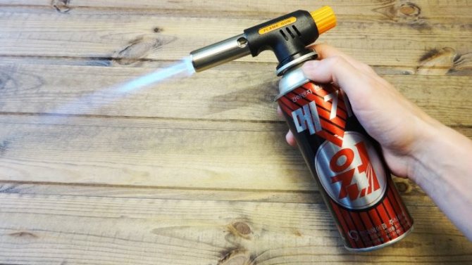
Propane gas burner for brazing and its device
The design of the manual gas burner is constantly being improved, becoming more ergonomic and modern, featuring ease of use and convenience. Elements that are included in the design of the tool make it possible to ensure the safety of soldering. The torch requires the simultaneous use of combustible materials, soldering kits, micro-soldering irons.
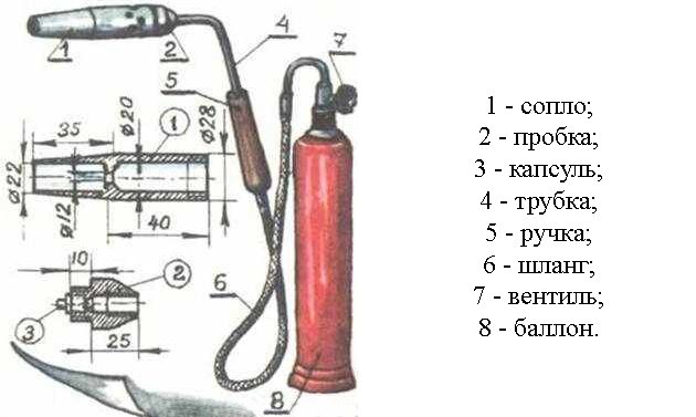
Figure 1. Diagram of a propane gas burner.
With the help of a propane burner, it is possible to perform crimping of couplings and reflow bitumen roll materials in the process of waterproofing, roofing, procedures related to the burning of wooden surfaces. The presence of the advantages of this device lies in the low cost of propane, readiness for work, rapid heating of parts to the required temperature.
A flexible rubber hose is used to connect the burner and the cylinder, for which a protective metal sheath is used. The gas supply can be regulated by a tap, which is placed between the hose and the cylinder. A hose equipped with a faucet is commercially available in stores, as are special cans.
The elements included in the gas burner are marked with numbers in fig. 1: 1 - nozzle; 2 - cork; 3 - capsules; 4 - tube; 5 - handle; 6 - hose; 7 - valve; 8 - balloon.
It is very convenient to use small cylinders that hold about 0.9 liters of propane-butane in a liquefied state. Such a cylinder will last for 4-5 hours with continuous burning of the device. If the cylinder has a capacity of 5.5 liters, then it is designed for 72 hours of continuous burning. It should be borne in mind that devices equipped with small cylinders are lighter and more convenient. They can be refueled at any gas station in any city or large village.
How to make a burner yourself
Argon welding torch device.
A home-made gas burner is characterized by the presence of the following components: nozzles, plugs, handles, tubes and a capsule that can be unscrewed from a purchased hose. When making your own nozzles and plugs, they are turned using a lathe from materials such as steel or brass.When making a nozzle, the internal thread is cut on one side. Having made an indent from the thread, a hole is drilled through which air will be supplied. On the plug itself, a thread must also be cut, only external, with the help of which the plug and the nozzle are connected together.
The next step is to drill two through holes and tap the threads. It should be cut for a standard capsule for one hole, and the other hole is made for threading along a tube that is screwed into the plug and bent at a certain angle to its axis. On the other end of the tube, a handle made of wood or ebonite is tightly fitted, which has a pre-drilled hole along the axis. A nut with a washer is used to secure the lower end of the tube. The free end of the tube is screwed into the hose, which is connected to the gas cylinder.
Types and functions of burners

For space heating, not only stationary heating systems are used.
There are four portable devices that are more convenient to use in some circumstances:
- Plate
- Lamp
- Heater
- Burner
Natural gas heaters are classified as air heaters.
The design of these devices is simple:
- housing,
- gas stove,
- heat exchanger,
- element capable of heating,
- balloon.
Each type of heater always has an additional possibility of connecting to a gas pipeline.
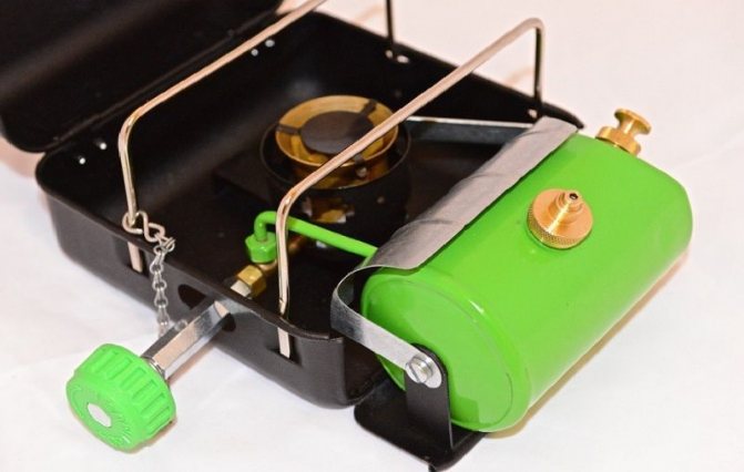
The stove works thanks to a fuel tank. With this device, cooking becomes comfortable regardless of location. This unit includes a robust housing. The body itself is made of high quality steel, which is further covered with a special enamel that protects against damage of various nature.
A lamp powered by gaseous fuel is a kind of element that emits light. The design of the lamp is similar to that of a burner.
The difference lies in the fact that its head is represented by a rod, on which a special catalytic mesh is put on, which is the direct source of the glow.
For protection, a glass shade is put on over the mesh.
There are burners complete with add-ons to improve the performance of the appliances.
First of all, it is worth considering the classification of burners depending on the type of fuel used:
Gas
This type is common - natural gas refers to the fuel available to the consumer.
Gas burner devices are divided into two types in accordance with the method of supplying the oxidizer to the working area: pressurized and injection.
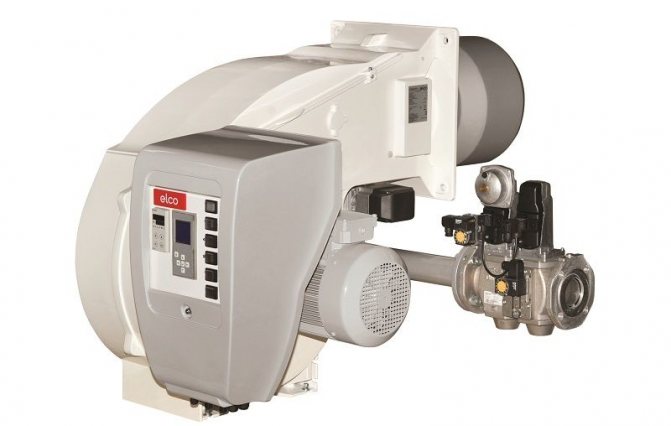
Pressurized burners.
They run on gaseous fuel and differ significantly in design - a built-in fan, mechanical delivery of the oxidizer (air) to the working area is provided.
With the help of the fan, the power is regulated and, in accordance with this, the operation of the device is improved, which affects the efficiency.
Additional noise is considered a disadvantage, but this is eliminated by installing special noise reduction add-ons.
Injection burners also called atmospheric. Such a device is most often included in the additional standard equipment for boilers. The operation of the device consists in supplying air to the working area due to the "injection effect" - the required volume of oxidizer required for the full flow of the combustion process enters the flow of gaseous fuel using high pressure.
During manufacture, the device is set to standard settings aimed at working with natural gas.
In order for the heating system to run on liquefied gas, additional equipment will be required.
The advantages of this type of burner devices are simplicity of design, absence of noise, complete safety, and long service life.
Liquid fuel
For oil burners, petroleum products are used as fuel, which go through various stages of processing. Biofuel or waste oil is also used. Those burner devices that perform work using diesel fuel are popular.
Diesel burners are not inferior to gas burners in terms of the quality of work.
At the same time, maintenance does not require large costs, the power of their work is a constant value and, which is no less important, they are able to work in conditions of negative temperatures.
Burners operating on fuel oil are considered economical, since fuel oil has a low cost, reliable in terms of a long service life of the device without preventive maintenance.
Oil burners are not used in domestic premises. The main area of application is objects of industrial importance, boiler houses operating for centralized heating.
Multi-fuel or combined
For these devices, it is possible to use various types of fuel without the need to install additional equipment. The cost of the device is high, but the efficiency is much lower than in other burners. Maintenance is much more complicated and therefore expensive.
Burner classification according to power:
- Low-power - ≥1500 W, used for a short time;
- Average power - from 1500 to 2500 W;
- Powerful - ≤ 2500 W.
The burners are connected to cylinders filled with gaseous fuel.
There are several types of cylinder connections, each suitable for any type of burner:
- Threaded connection - the burner is screwed onto the thread or it is done using an additional hose that is connected to the burner device.
- To perform a collet connection, a special push-type mount is used. The balloon, which is connected in this way, has a thin shell.
- The disposable connection cannot be disconnected from the burner until the fuel is completely consumed. This is due to the fact that there is no valve in the mount, and in case of untimely opening
- The valve connection is reliable, since even the slightest fuel leaks are avoided.
Some burners are equipped with additional functions that simplify the use of this device.

Power regulator... It allows you to adjust the power of the burner device, it is located on a threaded union, which is screwed to the cylinder. Since the regulator is located at a considerable distance directly from the burner, it is not always possible to keep the power under control. To eliminate this problem, two regulators are installed - on the burner device and on the fitting.
Piezo ignition... This addition greatly simplifies the initial stage of work. The ignition switch is located so that the burner start button is located under it. Therefore, the operating principle of the entire system is simple.
In high humidity, the device may malfunction.
Preheating... The operation of the system lies in the fact that the part of the pipe through which the fuel enters the combustion site is located not far from the burner head, therefore, in working condition, it is enveloped in a flame.
Classification of gas burners. Burner specifications.
Gas-burner
Is a device for mixing oxygen with gaseous fuel in order to supply the mixture to the outlet and burn it to form a stable flame.In a gas burner, gaseous fuel supplied under pressure is mixed in a mixing device with air (air oxygen) and the resulting mixture is ignited at the outlet of the mixing device to form a stable constant flame.
Gas burners offer a wide range of benefits. The construction of a gas burner is very simple. Its start-up takes a split second and such a burner works almost flawlessly. Gas burners are used for heating boilers or industrial applications.
Today there are two main types of gas burners, their separation is carried out depending on the method used for the formation of a combustible mixture (consisting of fuel and air). Distinguish between atmospheric (injection) and supercharged (ventilation) devices. In most cases, the first type is part of the boiler and is included in its cost, while the second type is most often purchased separately. Forced gas burners as a combustion tool are more efficient, since they are supplied with air by a special fan (built into the burner).
Gas burners are intended for:
- supply of gas and air to the combustion front;
- mixture formation;
- stabilization of the ignition front;
- ensuring the required intensity of combustion.
Types of gas burners:
Diffusion burner -
a burner in which fuel and air are mixed by combustion.
Injection burner - pre-mixed gas burner
with air, in which one of the media necessary for combustion is sucked into the combustion chamber of another medium (synonym - ejection burner)
Hollow premix burner -
a burner in which the gas is mixed with a full volume of air in front of the outlets.
Non-hollow premix burner
–a burner in which the gas does not completely mix with the air in front of the outlets. Atmospheric gas burner–Injection gas burner with partial premixing of gas with air, using secondary air from the environment surrounding the flame.
Special burner–a burner, the principle of operation and design of which determines the type of heating unit or features of the technological process.
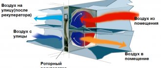
Recuperative burner–burner equipped with a recuperator for heating gas or air
Regenerative burner
- a burner equipped with a re-generator for heating gas or air.
Automatic burner–a burner equipped with automatic devices: remote ignition, flame control, fuel and air pressure control, shut-off valves and controls, regulation and signaling.
urine burner–gas burner, in which the energy of the escaping gas jets is used to drive the built-in fan, which blows air into the burner.
Ignition burner
–auxiliary burner used to ignite the main burner.
The most applicable today are the classification of burners by the method of air supply, which are divided into:
- blow-free - air enters the furnace due to rarefaction in it;
- injection - air is sucked in due to the energy of the gas stream;
- blast - air is supplied to the burner or furnace by means of a fan.
Gas burners are used at various gas pressures: low - up to 5000 Pa, average - from 5000 Pa to 0.3 MPa, and high - more than 0.3 MPa. Most often they use burners operating at medium and low gas pressure.
The thermal power of a gas burner is of great importance, which can be maximum, minimum and nominal.
During long-term operation of the burner, where a greater amount of gas is consumed without breaking off the flame, the maximum thermal power is achieved.
The minimum heat output occurs with stable operation of the burner and the lowest gas consumption without flame breakthrough.
When the burner is operating at a nominal, providing maximum efficiency with the greatest completeness of combustion, the gas flow rate is achieved by the nominal thermal power.
It is allowed to exceed the maximum thermal power over the nominal by no more than 20%. If the rated thermal power of the burner according to the passport is 10,000 kJ / h, the maximum should be 12,000 kJ / h.
Another important feature of gas burners is the range of heat output regulation.
Today, a large number of burners of various designs are used. A burner is selected according to certain requirements, which include:
stability with changes in thermal power, reliability in operation, compactness, ease of maintenance, ensuring the completeness of gas combustion.
The main parameters and characteristics of the used gas burner devices are determined by the requirements:
- thermal power, calculated as the product of the hourly gas consumption, m3 / h, by its lower calorific value, J / m3, and which is the main characteristic of the burner;
- parameters of the combustion gas (net calorific value, density, Wobbe number);
- rated thermal power, equal to the maximum power attainable during long-term operation of the burner with a minimum ‘excess air ratio and provided that the chemical underburner does not exceed the values set for this type of burner;
- nominal gas and air pressure corresponding to the nominal thermal power of the burner at atmospheric pressure in the combustion chamber;
- nominal relative torch length equal to the distance along the torch axis from the outlet section (nozzle) of the burner at nominal thermal power to the point where the carbon dioxide content at α = 1 is equal to 95% of its maximum value;
- coefficient of limiting regulation of thermal power, equal to the ratio of the maximum thermal power to the minimum;
- coefficient of operating regulation of the burner in terms of thermal power, equal to the ratio of the rated thermal power to the minimum;
- pressure (vacuum) in the combustion chamber at the rated power of the burner;
- content of harmful impurities in combustion products;
- heat engineering (luminosity, degree of blackness) and aerodynamic characteristics of the torch;
- specific metal and material consumption and specific energy consumption, referred to the rated thermal power;
- the sound pressure level generated by the operating burner at the rated heat output.
Burner requirements
Based on the operating experience and analysis of the design of burners, it is possible to formulate the basic requirements for their design.
The burner design should be as simple as possible: without moving parts, without devices that change the cross-section for the passage of gas and air, and without complex shaped parts located near the burner nose. Complex devices do not justify themselves during operation and quickly fail under the influence of high temperatures in the working space of the furnace.
The sections for the outlet of gas, air and gas-air mixture should be worked out during the creation of the burner. During operation, all these sections must be unchanged.
The amount of gas and air supplied to the burner should be measured with throttle devices on the supply lines.
The cross-sections for the passage of gas and air in the burner and the configuration of the internal cavities should be chosen in such a way that the resistance on the path of gas and air movement inside the burner would be minimal.
The gas and air pressure should mainly provide the required speeds in the outlet sections of the burner. It is desirable that the air supply to the burner be regulated.Unorganized air supply as a result of vacuum in the working space or by partial injection of air with gas may only be allowed in special cases.
Burner designs.
The main elements of a gas burner: a mixer and a burner nozzle with a stabilizing device. Depending on the purpose and operating conditions of the gas burner, its elements have a different design.
IN diffusion burners
gas, gas and air are supplied to the combustion chamber. The mixing of gas and air takes place in the combustion chamber. Most diffusion gas burners are mounted on the walls of a furnace or furnace. In boilers, the so-called. gas hearth burners, which are located inside the furnace, in its lower part. A gas hearth burner consists of one or more gas distribution pipes in which holes are drilled. The pipe with holes is installed on the grate or hearth of the furnace in a slotted channel lined with refractory bricks. The required amount of air enters through the refractory slotted channel. With such a device, the combustion of gas streams emerging from the holes in the pipe begins in the refractory channel and ends in the furnace volume. Bottom burners have low resistance to the passage of gas, so they can work without forced blast.
Gas diffusion burners are characterized by a more uniform temperature along the length of the flame.
However, these gas burners require a higher excess air ratio (compared to injection ones), and also create lower thermal stresses in the furnace volume and worse conditions for gas afterburning in the tail part of the flame, which can lead to incomplete gas combustion.
Diffusion burners
gas are used in industrial furnaces and boilers, where a uniform temperature is required along the length of the torch. In some processes, gas diffusion burners are indispensable. For example, in glass, open-hearth and other furnaces, when the combustion air is heated to temperatures exceeding the ignition temperature of combustible gas with air. Gas diffusion burners are also successfully used in some hot water boilers.
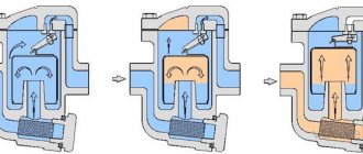
IN injection burners
combustion air is sucked in (injected) due to the energy of the gas jet and their mutual mixing takes place inside the burner body. Sometimes in gas injection burners the suction of the required amount of combustible gas, the pressure of which is close to atmospheric, is carried out by the energy of the air stream. In full-mixing burners (all the air necessary for combustion is mixed with the gas), operating on medium-pressure gas, a short flame is formed, and combustion ends in a minimum furnace volume. In partial-mixed gas injection burners, only a part (40 ÷ 60%) of the air required for combustion (the so-called primary air) is supplied, which is mixed with the gas. The rest of the air (the so-called secondary air) enters the flame from the atmosphere due to the injecting action of gas-air jets and rarefaction in the furnaces. Unlike medium pressure gas injection burners, low pressure burners form a homogeneous gas-air mixture with a gas content greater than the upper flammability limit; These gas burners are stable in operation and have a wide range of heat loads.
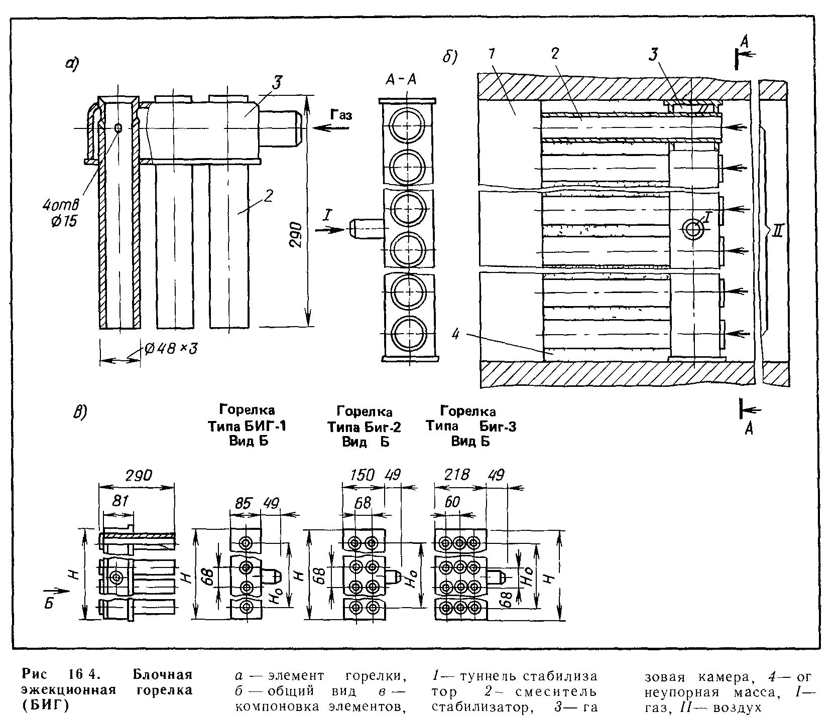
For stable combustion of the gas-air mixture in injection burners of medium and high pressure gas, stabilizers are used: additional igniting torches around the main flow (burners with an annular stabilizer), ceramic tunnels, inside which combustion of the gas-air mixture takes place, and plate stabilizers that create a vortex in the flow path.
In furnaces of significant dimensions, gas injection burners are collected in blocks of 2 or more burners.
Infrared gas injection burners (the so-called flameless burners) are widely used, in which the main amount of heat obtained during combustion is transmitted by radiation, because the gas burns out on the emitting surface in a thin layer, without a visible flame. Ceramic nozzles or metal meshes serve as the emitting surface. These burners are used to heat rooms with a high rate of air exchange (gyms, retail premises, greenhouses, etc.), to dry painted surfaces (fabrics, paper, etc.), to heat frozen soil and bulk materials, in industrial furnaces. For uniform heating of large surfaces (furnaces of oil refineries and other industrial furnaces), the so-called. panel injection radiant burners. In these burners, the gas-air mixture from the mixer enters the common box, and then the mixture is distributed through the tubes to separate tunnels, in which its combustion takes place. Panel burners have small dimensions and a wide control range, and are insensitive to back pressure in the combustion chamber.
The use of gas turbine burners is increasing, in which air is supplied by an axial fan driven by a gas turbine. These burners were proposed at the beginning of the 20th century (Eikart's turbo burner). Under the action of the reactive force of the outflowing gas, the turbine, shaft and fan are rotated in the direction opposite to the outflow of gas. The burner capacity is regulated by the pressure of the incoming gas. Gas turbine burners can be used in boiler furnaces. High-pressure gas turbine burners with self-supply of air through recuperators and air economizers are promising: gas-fuel oil burners of high efficiency operating on heated and cold air.
Burners have the following requirements:
1. The main types of burners must be manufactured at the factories in series according to technical conditions. If the burners are made according to an individual project, then upon commissioning they must undergo tests to determine the main characteristics;
2. Burners must ensure the passage of a given amount of gas and the completeness of its combustion with a minimum air flow rate α, with the exception of burners for special purposes (for example, for furnaces in which a reducing environment is maintained);
3. While ensuring the specified technological mode, the burners must ensure the minimum amount of harmful emissions into the atmosphere;
4. The level of noise generated by the burner should not exceed 85 dB when measured with a sound level meter at a distance of 1 m from the burner and at a height of 1.5 m from the floor;
5. Burners must operate stably without separation and flame breakthrough within the design range of heat output regulation;
6. For burners with preliminary complete mixing of gas with air, the flow rate of the gas-air mixture must exceed the speed of flame propagation;
7. To reduce the consumption of electricity for auxiliary needs when using burners with forced air supply, the resistance of the air path should be minimal;
8. To reduce operating costs, the burner design and stabilizing devices should be sufficiently easy to maintain, convenient for revision and repair;
9. If it is necessary to preserve the reserve fuel, the burners must ensure a quick transfer of the unit from one fuel to another without disrupting the technological regime;
10. Combined gas-oil burners should provide approximately the same quality of combustion of both types of fuel - gas and liquid (fuel oil).
Diffusion burners
In diffusion burners, the air necessary for gas combustion is supplied from the surrounding space to the flame front due to diffusion.
Such burners are usually used in household appliances.They can also be used when the gas flow rate is increased, if it is necessary to distribute the flame over a large surface. In all cases, the gas is supplied to the burner without admixture of primary air and is mixed with it outside the burner. Therefore, these burners are sometimes referred to as external mixing burners.
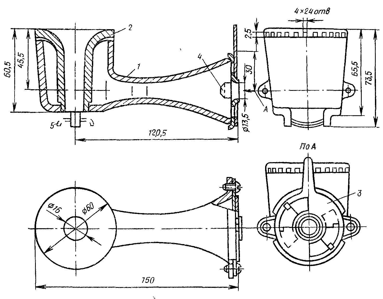
The simplest in design diffusion burners (Fig. 7.1) represent a pipe with drilled holes. The distance between the holes is chosen taking into account the speed of propagation of the flame from one hole to another. These burners have low heat outputs and are used for burning natural and low-calorific gases under small water heaters.
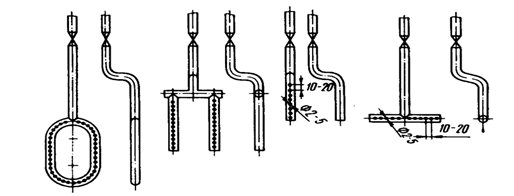
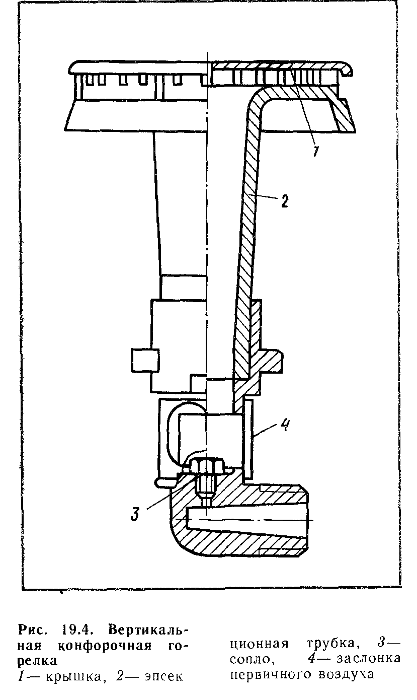
Fig. 7.1. Diffusion burners
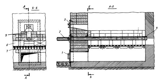
Figure 7.2. Bottom diffusion burner:
1 - air regulator; 2 - burner; 3 - viewing window; 4 - centering glass; 5 - horizontal tunnel; 6 - brick layouts; 7 - grate
Diffusion type industrial burners include bottom slot burners (fig. 7.2). Usually they are a pipe with a diameter of up to 50 mm, in which holes up to 4 mm in diameter are drilled in two rows. The channel is a slot in the bottom of the boiler, hence the name of the burners - bottom slot.
From the burner 2, the gas enters the furnace, where air enters from under the grate 7. Gas streams are directed at an angle to the air flow and evenly distributed over its cross section. The process of mixing gas with air is carried out in a special slot made of refractory bricks. Thanks to such a device, the process of mixing gas with air is enhanced and a stable ignition of the gas-air mixture is ensured.
The grate is laid with refractory bricks and several slots are left in which pipes with drilled holes are placed for gas outlet. Air under the grate is supplied by a fan or as a result of vacuum in the firebox. The refractory walls of the slot are combustion stabilizers, prevent flame separation and, at the same time, increase the heat transfer process in the furnace.
Injection burners.
Injection burners are called burners in which the formation of a gas-air mixture occurs due to the energy of a gas stream. The main element of an injection burner is an injector that sucks air from the surrounding space into the burners.
Depending on the amount of injected air, the burners can be completely premixed with air or with incomplete air injection.
Burners with incomplete air injection.
Only part of the air necessary for combustion enters the combustion front, the rest of the air comes from the surrounding space. These burners operate at low gas pressure. They are called low pressure injection burners.
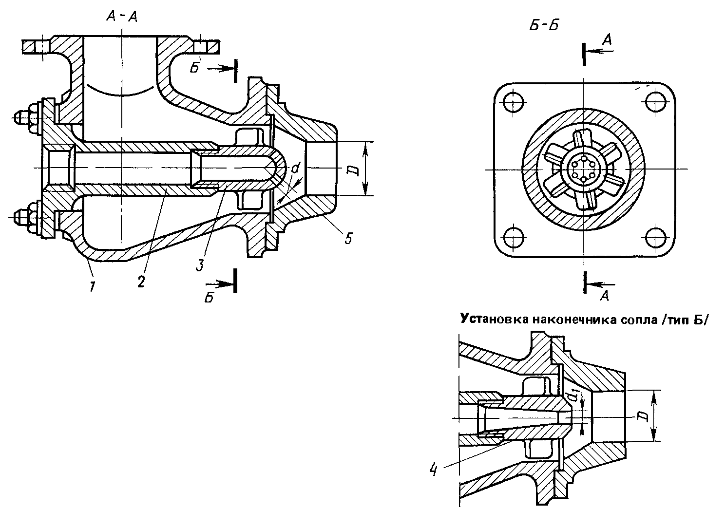
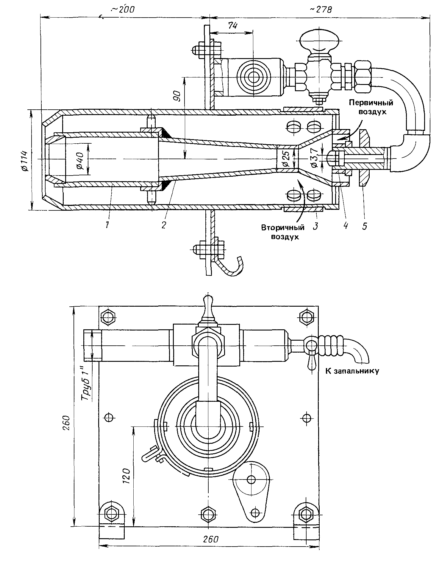
The main parts of the injection burners (fig. 7.3) are the primary air regulator, nozzle, mixer and manifold.
The primary air regulator 7 is a rotating disc or washer and regulates the amount of primary air entering the burner. Nozzle 1 serves to convert the potential energy of gas pressure into kinetic energy, i.e. to give the gas jet a speed that allows the required air to be sucked in. The burner mixer consists of three parts: injector, confuser and diffuser. Injector 2 creates a vacuum and air suction. The narrowest part of the mixer is confuser 3, which levels the flow of the gas-air mixture. In the diffuser 4, the final mixing of the gas-air mixture and an increase in its pressure occur due to a decrease in speed.
From the diffuser, the gas-air mixture enters the manifold 5, which distributes the gas-air mixture through the holes 6. The shape of the manifold and the location of the holes depends on the type of burners and their purpose.
Low-pressure injection burners have a number of positive qualities, due to which they are widely used in household gas appliances, as well as in gas appliances for catering and other household gas consumers. The burners are also used in cast iron heating boilers.
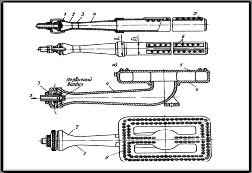
Fig. 7.3. Injection atmospheric gas burners
but
- low pressure;
b
- burner for a cast iron boiler; 1 - nozzle. 2 - injector, 3 - confuser, 4 - diffuser, 5 - collector. 6 - holes, 7 - primary air regulator
The main advantages of low pressure injection burners: simplicity of design, stable operation of burners with changing loads; reliability and ease of maintenance; noiselessness of work; the possibility of complete gas combustion and operation at low gas pressures; lack of air supply under pressure.
An important characteristic of incompletely mixed injection burners is injection ratio
- the ratio of the volume of injected air to the volume of air required for complete combustion of the gas. So, if for complete combustion of 1 m3 of gas 10 m3 of air is needed, and the primary air is 4 m3, then the injection ratio is 4: 10 = 0.4.
Burners are also characterized by injection rate
- the ratio of the primary air to the gas flow rate of the burner. In this case, when 4 m3 of air is injected per 1 m3 of combusted gas, the injection rate is 4.
The advantage of injection burners: the property of their self-regulation, i.e. maintaining a constant proportion between the amount of gas supplied to the burner and the amount of injected air at a constant gas pressure.
Mixing burners. Forced air burners.
Forced air burners are widely used in various heating devices in municipal and industrial enterprises.
According to the principle of operation, these burners are divided into burners with premixing of gas (Fig. 7.4) and fuel and burners without preliminary preparation of the gas-air mixture. Burners of both types can operate on natural, coke oven, blast furnace, mixed and other low and medium pressure combustible gases. Working regulation range - 0.1 ÷ 5000 m3 / h.
The air to the burners is supplied by low and medium pressure centrifugal or axial fans. Fans can be installed on each burner or one fan for a specific group of burners. In this case, as a rule, all the primary air is supplied by fans, while the secondary air practically does not affect the quality of combustion and is determined only by the suction of air into the combustion chamber through leaks in the combustion fittings and hatches.
The advantages of burners with forced air supply are: the possibility of using in combustion chambers with different back pressure, a significant range of regulation of the heat output and the gas-air ratio, relatively small torch sizes, insignificant noise during operation, simple design, the possibility of preheating gas or air and the use of burners large unit capacity.
Low pressure burners are used at a gas flow rate of 50 ÷ 100 m3 / h, at a flow rate of 100 ÷ 5000 it is advisable to use medium pressure burners.
The air pressure, depending on the design of the burner and the required thermal power, is taken to be 0.5 ÷ 5 kPa.
For better mixing of the fuel-air mixture, gas is supplied to most burners in small jets at different angles to the flow of the primary blast air. In order to intensify the mixture formation, the air flow is given a turbulent motion using specially installed vortex blades, tangential guides, etc.
The most common burners with forced internal mixing air include burners with a gas flow rate of up to 5000 m3 / h and more.They can provide a predetermined quality of preparation of the fuel-air mixture before it is fed into the combustion chamber.
Depending on the design of the burner, the processes of mixing fuel and air can be different: the first is the preparation of the fuel-air mixture directly in the mixing chamber of the burner, when the finished gas-air mixture enters the furnace, the second is when the mixing process begins in the burner and ends in the combustion chamber. In all cases, the speed of the outflow of the gas-air mixture is different from 16 to 60 m / s. Intensification of gas and air mixture formation is achieved by jet gas supply, the use of adjustable blades, tangential air supply, etc. When gas jet supply, burners are used with a central gas supply (from the center of the burner to the periphery) and with a peripheral one.
The maximum air pressure at the burner inlet is 5 kPa. It can work with back pressure and vacuum in the combustion chamber. In these burners, unlike external mixing burners, the flame is less luminous and relatively small in size. Ceramic tunnels are most often used as stabilizers. However, all methods discussed above can be used.
The GNP type burner with forced air supply and central gas supply, designed by the specialists of the Teploproekt Institute, is intended for use in furnaces with significant thermal stresses. These burners are designed to swirl the air flow using blades. The burner set includes two nozzles: type A nozzle used for short-flame gas combustion with 4 ÷ 6 gas outlet holes directed perpendicularly or at an angle of 45 ° to the air flow, and type B nozzle used to obtain an elongated flame and having one central hole directed parallel to the air flow. In the latter case, the premixing of gas and air is much worse, which leads to an elongation of the flame.
Flare stabilization is ensured by the use of a class A fireclay brick fire-resistant tunnel. Burners can operate in cold and heated air. The excess air ratio is 1.05. Burners of this type are used in steam boilers, bakery industry.
The GMG two-line gas-oil burner is designed to burn natural gas or low-sulfur liquid fuels such as diesel, household fuel, naval fuel oils F5, F12, etc. Co-firing of gas and liquid fuel is allowed.
The burner gas nozzle has two rows of holes directed at 90 ° to each other. The holes on the side surface of the nozzle allow gas to be supplied to the swirling secondary blast air stream, the holes on the end surface to the swirling primary air stream.
The process of formation of a gas-air mixture in burners with forced air supply begins directly in the burner itself, and ends already in the furnace. During combustion, the gas burns out with a short and non-luminous flame. The air required for gas combustion is forced into the burner by means of a fan. Gas and air are supplied through separate pipes.
This type of burner is also called two-wire or mixing burners. The most commonly used burners operate at low gas and air pressure. Also, some burner designs are used at medium pressure.
Burners are installed in boiler furnaces, heating and drying ovens, etc.
The principle of operation of a forced air burner:
The gas enters the nozzle 1 with a pressure of up to 1200 Pa and leaves it through eight holes with a diameter of 4.5 mm. These holes must be at a 30 ° angle to the burner axis. Special blades, which set the rotational movement of the air flow, are located in the body 2 of the burner.During operation, the gas flows in small streams into the swirling air stream, which aids in good mixing. The burner ends with a ceramic tunnel 4 with an ignition hole 5.
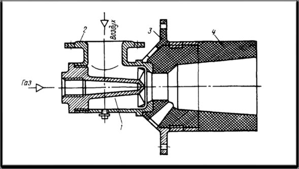
Fig. 7.4. Forced air burner:
1 - nozzle; 2 - case; 3 - front plate; 4 - ceramic tunnel.
Forced air burners have a number of advantages:
-high performance;
- a wide range of performance regulation;
–The ability to work on heated air.
In the existing various designs of burners, the intensification of the formation of the gas-air mixture is achieved in the following ways:
–Division of gas and air flows into small flows, in which mixture formation takes place;
–Supply of gas in the form of small streams at an angle to the air flow;
- twisting the air flow with various devices built into the inside of the burners.
Combined burners.
Combined burners are burners operating simultaneously or separately on gas and fuel oil or on gas and coal dust.
They are used in case of interruptions in the gas supply, when it is urgently necessary to find another type of fuel, when the gas fuel does not provide the required temperature regime of the furnace; gas supply for this is made only at a certain time (at night) to equalize the daily irregularities in gas consumption.
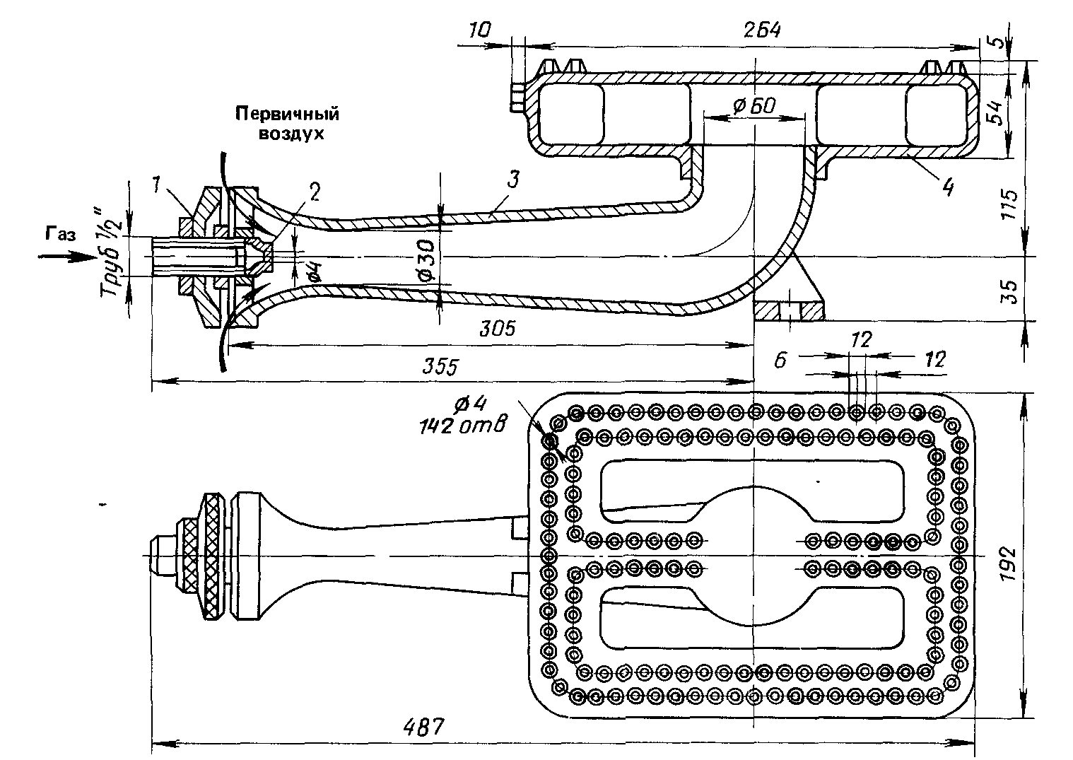
The most widespread are oil-gas burners with forced air supply. The burner consists of gas, air and liquid parts. The gas part is a hollow ring with a gas inlet and eight tubes for gas atomization.
The liquid part of the burner consists of an oil head and an inner tube ending in nozzle 1 (Fig. 7.5).
Fuel oil supply to the burner is regulated by a valve. The air part of the burner consists of a body, a swirler 3, an air damper 5, with which the air supply can be regulated. The swirler serves for better mixing of the fuel oil jet with air. Air pressure 2 ÷ 3 kPa, gas pressure up to 50 kPa, and fuel oil pressure up to 0.1 MPa.

Fig. 7.5. Combined oil-gas burner:
1 - oil nozzle, 2 - air chamber, 3 - swirler, 4 - gas outlet tubes, 5 - air regulating damper.
The use of dual fuel burners gives a higher effect than the simultaneous use of gas burners and oil burners or gas pulverized coal burners.
Combined burners are necessary for the reliable and uninterrupted operation of gas-using equipment and installations of large industrial enterprises, power plants and other consumers for which an interruption in operation is unacceptable.
Consider the principle of operation of a combined dust and gas burner designed by Mosenergo (Fig.7.6)
When operating on coal dust, a mixture of primary air with coal dust is supplied to the furnace through the annular channel 3 of the central pipe, and the secondary air enters the furnace through the scroll 1.
Fuel oil is used as a reserve fuel, in this case a fuel oil nozzle is installed in the central pipe. When converting the burner to gas fuel, the oil nozzle is replaced by an annular channel through which the gas fuel is supplied.
In the central part of the channel, a pipe with a cast iron tip 2 is installed. The tip 2 has oblique slots through which the gas escapes and intersects with the swirling air flow coming out of the volute 1. In improved burner designs, instead of slots 115 holes with a diameter of 7 mm are provided in the tip. As a result, the gas exit velocity is almost doubled (150 m / s).
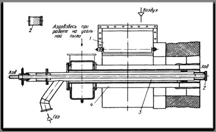
Fig. 7.6. Combined gas and dust burner with central gas supply.
1 - a snail for twisting the air flow, 2 - a tip of gas supply pipes,
3 - an annular channel for supplying a mixture of primary air with coal dust.
New burner designs use peripheral gas flow, in which gas jets, which have a higher velocity than air ones, cross a swirling air stream moving at a speed of 30 m / s at a right angle. This interaction of gas and air flows ensures fast and complete mixing, as a result of which the gas-air mixture burns with minimal losses.
7.3. Automation of gas combustion processes.
The properties of gas fuel and modern designs of gas burners create favorable conditions for the automation of gas combustion processes. Automatic control of the combustion process increases the reliability and safety of operation of gas-powered units and ensures their operation in accordance with the most optimal mode.
Today, gas-powered plants use partial or complex automation systems.
Integrated gas automation consists of the following main systems:
- control automation;
- safety automation;
- emergency signaling;
–Technical control.
The regulation and control of the combustion process is determined by the operation of gas appliances and units in a given mode and ensuring the optimal mode of gas combustion. For this, the regulation of the combustion process is intended for the automation of regulation of household, municipal and industrial gas appliances and units. Thus, a constant temperature of the water in the tank is maintained for storage water heaters, a constant steam pressure for steam boilers.
The gas supply to the burners of gas-using installations is terminated by the safety automatics in the event of:
- extinction of the torch in the furnace;
- lowering the air pressure in front of the burners;
- increasing the steam pressure in the boiler;
- an increase in the temperature of the water in the boiler;
- lowering the vacuum in the furnace.
Deactivation of these installations is accompanied by corresponding sound and light signals. No less important is the control of the gas content of the room in which all gas appliances and units are located. For these purposes, solenoid valves are installed that stop the gas supply in cases of exceeding the maximum permissible concentration in the ambient air of CH4 and CO2.
It is possible to achieve the optimal mode in the conditions of the technological process with the help of thermal control devices
The operating conditions of gas-using equipment determine the degree of its automation.
Remote control of gas-using installations is achieved through the use of monitoring and alarm devices.
Burner calculations.
In gas-oil furnaces equipped with modern burners with automatic control of the combustion process, it became possible to burn natural gases and fuel oil with small excess air practically in the absence or small value of chemical incompleteness of combustion (less than 0.5%). Therefore, it is recommended to maintain the combustion process of these fuels with the excess air ratio behind the superheater not higher than 1.03 ÷ 1.05.
Burner advantages
Positive aspects of burners operating on gaseous fuels:
- Ease of use, since the design features of this type of burners are primitive and do not require additional experience;
- There is no need for preparation before starting to use;
- Achieving high capacities;
- Flame regulation;
- Cleanliness, and this is important, since there is no need to allocate additional time to clean the accessories;
- There is no need for additional maintenance of the burner elements, because carbon deposits do not remain after fuel combustion;
- Low cost price.
Advantages of liquid fuel devices:
- This type of fuel is consumed much more economically than gas;
- Throughout the work, the power indicator remains unchanged;
- Works at low temperatures.
The main elements of the auto-control system
Devices included in the burner electrical circuit to start the automatic operation of the device:
- Relay max. and minimal. gas pressure - has a light structure, which affects its long service life. The principle of operation is that the gas pressure affects the membrane, and when it deviates from the set mode, the system is triggered, and the control valve performs the required work. Relay min. gas pressure protects against a decrease in gas pressure to a critical point, and the maximum pressure switch adjusts, preventing an increase in the permissible value.
- Relay for min and max pressure of the heating agent - protects the heating system from excessive decrease and increase in pressure of the heating device. Both options are dangerous and undesirable for the continued operation of the boiler, therefore, when a critical point (lower or upper) is reached, the boiler shuts down, that is, the gas supply stops.
- The combustion controller is a part that integrates the operation of the entire burner into an overall process. The operation of gas burners of heating boilers with automation is divided into several sections, which correspond to the required position of the fuel control valve and air damper. Having received a signal about a low temperature, the controller opens the appropriate mechanisms to increase the combustion force. The controller's operation is based on signals from different sensors (temperature, pressure).
- The thermostat is a signaling device for reaching the limit temperature levels. On its signal, a change in combustion modes is carried out.
- Boiler filling sensor - necessary to protect the burner from starting, without the presence of heat carrier in the boiler.
The connection of the sensors largely depends on the manufacturer of the boiler. This data can be seen in the passport of the device, and the features of connecting the sensors are carefully described in additional instructions. In this case, the connection and setting of the automatic system must be controlled by a gas service employee. In his presence, commissioning is also carried out, with the indispensable drawing up of an act on the serviceability of the equipment for safe operation.
Problems
Any type of burner device also has negative sides.
Disadvantages of gas powered devices:
- Under natural conditions, there is no way to replenish fuel reserves;
- Inability to transport gas cylinders on airplanes and trains by public transport;
- At a negative temperature, gaseous fuel tends to thicken, as a result of which the pressure indicator decreases and, ultimately, the burner device fails.
Negative qualities of the work of devices using liquid fuel:
- Parts of the burner structure are prone to deviations in operation, therefore, they must be serviced quite often;
- High price;
- Possibility of fuel leakage;
- The need for additional preparation before starting work;
- Decent weight and size.
The principle of operation of a gas burner
Depending on the type of gas burner, the soldering process can be manual or automatic. The device involves mixing air (oxygen) with a combustible gas in the required proportions, for which the required pressure is set. Each specific design of the gas apparatus has its own pressure level. The main component is combustible gas, which allows creating a chemical combustion reaction with a high level of flame temperature of the device. It has a different chemical composition. The gas is stored in cylinders where it is pumped under pressure. The supply of combustible gas in the form of saturated hydrocarbons, carried out under pressure, is carried out in the area of the gas burner nozzle. There the process of mixing gas and air takes place.
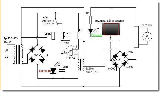
Electrical diagram of a hydrogen burner.
If a gas torch is used for cutting metal, gasoline vapors as well as hydrogen can be used. Basically, such a device is used when it is required to carry out special jewelry work that requires the use of a gas-powered soldering iron. For the manufacture of soldering irons, copper alloys are used. The burners themselves are equipped with manual or automatic controls.
When the edges of the parts used in the welding process melt together, gas soldering irons create a temperature that can melt the solder, and not the part material, which only heats up during welding. This method allows you to connect two parts made of different metals, solder thin surfaces, etc.
Gas burners offer numerous advantages, such as producing a flame that is particularly resistant. For example, mini-devices allow soldering in windy conditions, so it is very convenient to work with such a device in an open area. In addition, roofing work can be carried out by heating the roofing materials. Roofing propane burners are highly efficient for insulating the roof. The use of propane is economical.
The main safety requirement when working with such devices is the complete absence of technical oils on their surface and on the welder's hands, which immediately leads to an explosion. The only drawback of the device is the requirement to equip a special workplace. However, special skills are required when working with the burner, otherwise there is a high risk of injury.
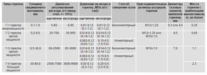
Gas burner technical data table.
Igniting the burner, the burning match is brought to the nozzle, and the taps are slightly closed at the same time. When the gas has ignited, the gas supply must be increased. The flame should be even and compact. When working with the burner, observe the safety precautions. There should be no flammable substances near the place of work. If the workplace is a table, then it must be upholstered with sheet metal. If there is a faint smell of gas, it means that a gas leak has occurred. It is necessary to suspend work to eliminate the causes of the gas leak.
Before starting work on the burner, it is manually checked for serviceability. At the same time, the tightness of each detachable connection of the mini-device, hose connections, etc. is checked. Having finished checking the instrument for tightness, they begin the process of setting the working gas pressure, taking into account the specific task.
To ignite the combustible mixture, open the valve in half, adjust the flame intensity using a valve or a burner reducer. This is how the mini-burner is prepared for high-quality work with metal.
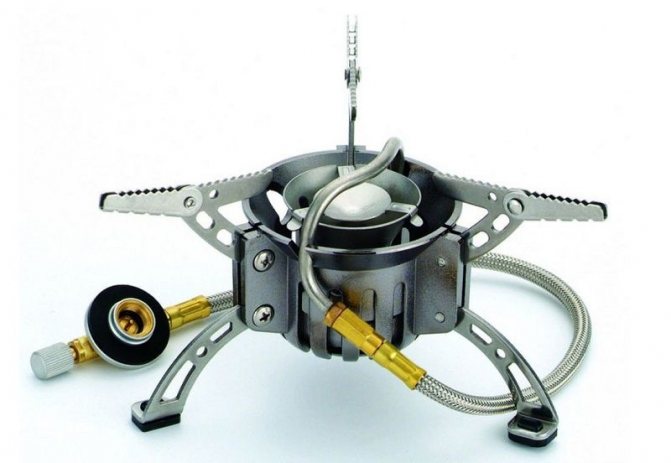
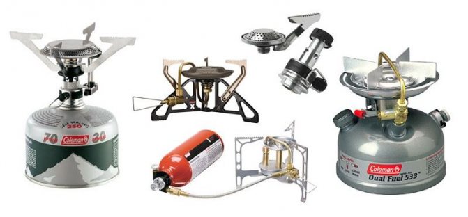
How to choose a burner
The required power of the device depends primarily on the number of consumers. With a small number of consumers, a low-power burner is sufficient. If there are 5 or 6 users, the device with the highest power is required. In the event that the number of users is much more, it is worth stocking up on several devices.
The design of the selected model depends only on personal preferences: a minimum size burner is required, or the cooking speed is important, and the device will become much larger.
For convenience, it is worth purchasing a device with piezo ignition.
Type of cylinder attachment. It is equally important to think about additional equipment. First of all, there is a need for a case for transporting the device. Convenient when a special cookware holder is included with the burner.
The additions also include special protection against gusts of wind - blowing out the flame. Such a device significantly saves fuel. When choosing an add-on, pay attention to the design, since the presence of plastic parts in it is unacceptable.
How does the automatic temperature control system work?
The simplest system for automatic regulation of the set temperature using a gas burner works like this: gas is supplied to the burner, which is ignited by the ignition function, and thus constant combustion occurs. In this case, the burner itself works at its full strength. When a certain temperature of the coolant or air in the room is reached, the automatic equipment of the gas burner extinguishes the fire.
To maintain the set temperature, the burner is constantly switched on and off.
Which is better
A multi-fuel burner is considered a good option, taking into account any conditions. Gas cylinders are not always possible to find, but liquid fuels are more common.
Multi-fuel burners have a power of 3500 watts. The fuel that suits them is both gas and petrol.
It is desirable that the burner kit includes: a cover for transportation, tools for preventive maintenance, necessary spare parts for minor repairs (gaskets, lubricants), a pump.
Please note that the built-in piezo ignition fails rather quickly.
For the entrant
- modern solutions strive to achieve complete combustion of gas with a minimum release of harmful substances in combustion products;
- they must ensure the maximum efficiency of using the heat obtained from fuel combustion;
- the ability to regulate the main parameters;
- lack of strong noise (no more than 85 dB);
- simplicity of design, providing ease of repair.
- operational safety;
- the possibility of using automation for control;
According to the gas combustion method, all burners can be divided into three groups:
- without preliminary mixing of gas with air - diffusion;
- with incomplete preliminary mixing of gas with air - diffusion-kinetic;
- with complete premixing of gas with air - kinetic.
Classification by air supply method:
- Air supply due to free convection;
- Air supply due to vacuum in the working space.
- Air injection with gas.
- Forced air supply from an external source.
- Forced air supply from the built-in fan (block burners).
- Forced air supply due to gas pressure (turbine burners).
- Injection of gas by air (forced supply of air injecting gas).
- Forced supply of a gas-air mixture from an external source.
Classification according to the degree of preparation of the combustible mixture:
- Without premixing.
- With partial primary air supply.
- With incomplete premixing.
- With full premixing.
Classification by the rate of flow of combustion products ()
- Up to 20 meters per second (low).
- From 20 to 70 meters per second (average).
- From 70 to 200 or more meters per second (high-speed burners).
Classification by the type of flow coming out of the burner
- Direct-flow.
- Spun open.
- Swirling open.
Classification, if possible, to regulate the characteristics of the flame:
- With non-adjustable torch characteristics
- With adjustable torch characteristics
Classification by localization of the combustion zone:
- Combustion takes place in a refractory tunnel or in the combustion chamber of a burner.
- Combustion takes place on the catalyst surface, in the catalyst bed.
- Combustion takes place in a granular refractory mass
- Combustion takes place on ceramic or metal nozzles
- Combustion takes place in the combustion chamber of the unit or in an open space
Classification by the ability to control the characteristics of the torch:
- With unregulated torch characteristics.
- With adjustable torch characteristics
Classification by capabilities use of the heat of combustion products:
— Without air and gas heating.
— Heated in an autonomous recuperator or regenerator.
— With air heating in a built-in recuperator or recuperator.
— Heated air and gas.
Classification by degree of automation:
- With manual control.
- With semi-automatic control.
- With automatic control.
In addition, burners are usually divided according to the gas pressure used in them: low - up to 5000 Pa, average - from 5000 Pa to 0.3 MPa and high - more than 0.3 MPa.
Another important characteristic is the thermal power of the burner, measured in kJ / h (Kilo-Juoli per hour)
Exploitation

Correct use of the device guarantees a long service life. If you follow the rules for using burner devices, then there will be no difficulties even for a novice user.
Remember that these devices are highly hazardous devices, use caution.
List of rules and recommendations:
- The device must be installed on a flat surface. If located incorrectly on an inclined surface, there is a possibility of an emergency.
- Never dry clothes or shoes with a burner.
- If you have an additional cylinder, protect it from sunlight.
- You cannot replenish gas cylinders with your own hands - refueling is done at specialized stations, additives are added to the gas fuel in certain proportions.
- Do not touch the heated surface during the operation of the device - you can get burned.
- During operation, the safety parts of the device must not be touched.
- Use is permissible only in rooms with good ventilation and during work, the approach to flammable objects is excluded.
- During operation, do not leave the device unattended.
- Before starting work, it is imperative to check the correct attachment of the fuel cylinder.
Any kind of burner device requires constant maintenance. First of all, it is required to carry out internal cleaning from time to time.
If we are talking about a multi-fuel burner, then there is a thin metal cable in the inside of the fuel line. It is designed to perform two functions. First of all, it works to warm up various fuel substances. Also, the function of this device includes cleaning assistance.
When dirty, cleaning is performed with some difficulty, because it is difficult to pull out the cable.
For this, a special device is used, which is called a gripper. For these purposes, an improvised tool similar to pliers is used.
If attempts to clean up are unsuccessful, it is required to warm up the fuel line. Having taken out the cable, it is important to warm it up until it turns red and hot.
This action removes the coke that has accumulated during operation. Then the cable is inserted into the pipe and removed again. It is advisable to perform this action two or three times.
For a more thorough cleaning: it is worth unscrewing the nozzle and flushing the system with fuel, which is poured there from a cylinder under high pressure.
A specially designed needle is used to clean the nozzle. This action is performed without reaching the item to be cleaned.
General rules for the maintenance of the burner device:
- In the event that there is a choice of the type of fuel, it is worth choosing a gaseous fuel, since it minimally clogs the system.
- When using liquid fuel, it is imperative to give preference only to purified substances, which reduce the likelihood of system failure, and are distinguished by the absence of a pungent and unpleasant odor.
- Ignition of a liquid fuel appliance is undesirable in confined spaces. This is especially true for tents.
- Cleaning the burner assembly as a preventive measure is very important, even if no signs of malfunction are found.
- Assembly and disassembly of the device must be carried out carefully, preferably with the use of special tools. There is a risk of damage to the threaded fasteners
- The pump from time to time needs to be treated with a special lubricant.
With strict adherence to the listed rules, many malfunctions and various inconveniences associated with deviations in the operation of the device are prevented.
There are several reasons for dividing this equipment into groups.
By area of application
On this basis, they are distinguished:
- universal burners that are suitable for most types of furnaces and furnaces;
- special models that have been developed for use in ovens of a specific design.
Naturally, special burners must be used strictly for their intended purpose, bearing in mind that they are incompatible with any other type of fire installation.
By the method of obtaining a fuel mixture
The pure gas in the burners is not combusted; it is included in the fuel mixture together with air. The formation of the fuel mixture can be carried out in various ways. Depending on this, burners can be divided into three groups:
- injection burners, in which air is supplied by suction;
- blowing burners in which air is supplied by injection;
- diffusion models, which are characterized by a natural flow of air to the flame.
Typically, injection burners are part of the boiler, while ventilation models are purchased as separate equipment. With the help of a blowing burner, a smooth and most accurate regulation of the power of the equipment can be ensured, which makes it possible to increase the efficiency of the system due to the rational use of fuel, that is, gas. Under optimal operating conditions of the equipment, not only fuel is saved, but also carbon dioxide is released into the environment in smaller quantities. However, there are some drawbacks to blowing burners. Their main disadvantage is the high noise level of their work.
The blowing gas burners themselves, in turn, can also be divided into three subspecies, depending on the type of air supply. It can be a forced air supply in combination:
- with full premixing;
- with partial premixing;
- with no pre-mixing.
To increase the intensity of obtaining a gas-air mixture, various mixing technologies are used: the gas can be directed in the form of thin jets, which are distributed at a certain angle to the air flow; gas can be divided into small streams, in which mixing will take place: air and gas streams can swirl under the influence of special built-in equipment.
With artificial air supply, it is possible to achieve an increase in the intensity of combustion of the fuel mixture, which allows reaching maximum power.
By the calorific value of the fuel burned in the burners
On this basis, gas burners are divided into three groups:
- low-calorie models. They are used for gas combustion, the calorific value of which does not exceed 8 MJ / m3. It can be blast furnace or generator gas;
- medium-calorie models. This type of burner is characterized by the heat of combustion of fuel on average 8-20 MJ / m3. It could be coconut gas;
- high-calorie models. In this case, the minimum heat of combustion of the fuel will be 20 MJ / m3.
High-calorific burners are used when burning associated petroleum and natural gases.
Flame localization
- on a refractory surface;
- in a porous, granular or perforated refractory mass;
- in a free torch;
- in a tunnel or combustion chamber (fireproof).
The last two varieties are used in boilers designed to heat the coolant (air, water, and so on). The first two types are used for heating using the infrared radiation method.
Overpressure
There are also three groups: low pressure burners (up to five kPa), medium pressure models (5-30 kPa) and high pressure models (over 30 kPa).Models of medium and low pressure are most in demand today. As for high-pressure devices, their area of use is currently limited to the combustion of low-calorific gases.
The above classification of gas burners is as complete as possible, thanks to which even non-specialists can navigate the variety of burner models on the modern market and make the right choice.
Evaluate your requirements, desires, capabilities, highlight for yourself the most significant characteristics of the burners, not forgetting about the intended area of use, load, and you can easily find an option that suits you in all characteristics. Remember that the right choice is the key to efficient operation of a gas burner for a long time.
Information taken from the site: vashdom.ru
Guarantee
When purchasing goods in specialized stores, a guarantee is provided.
This service applies to the performance of the device. There are also such cases when the guarantee also applies to the consumer properties of the goods.
Repair of burners at the expense of the organization is carried out if the device has a presentation, i.e. it retains seals, seals, complete safety of the case.
Therefore, before purchasing the device, make sure that it complies with the listed items, the declared characteristics and full functionality.
Most often, the warranty period is given for one year. But there are manufacturers who extend the term up to five years.
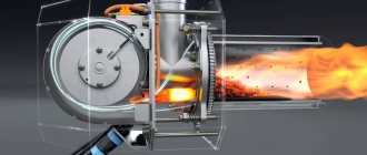
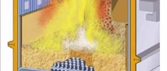
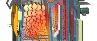
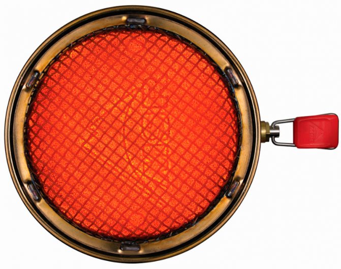
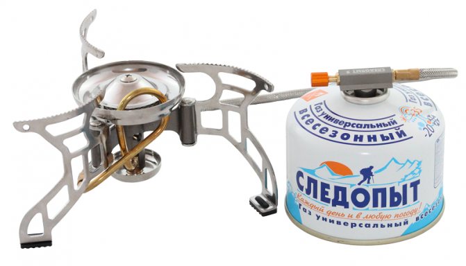
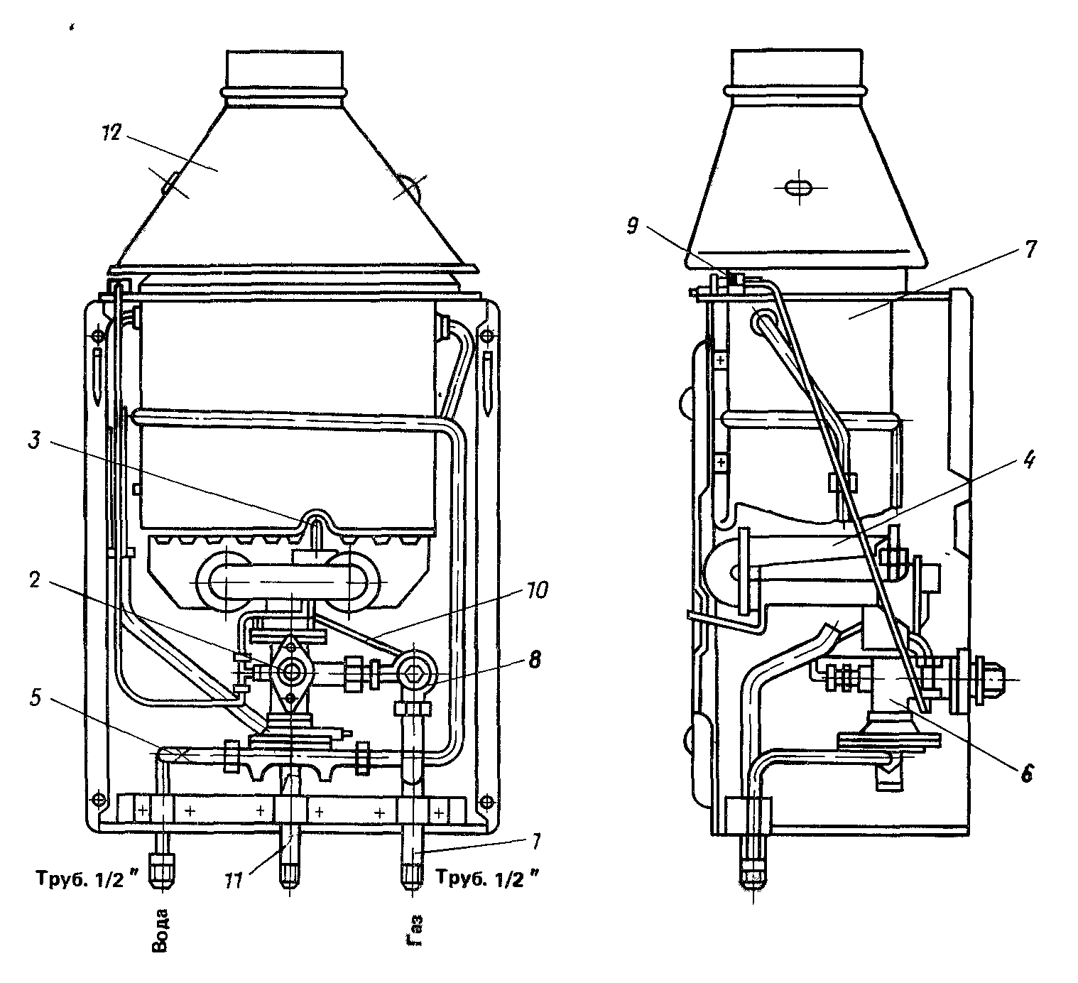
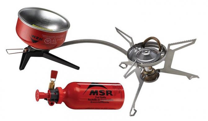
How it works
During combustion, gas leaves the cylinder through the pressure regulator and fills the cavity under the porous disc. Here, the fuel mixes with air and passes through the pores in the disc. Gas ignition occurs at the top and on the surface of the disc. The flame spreads evenly over the disc, ensuring stable heating of a wide surface. The flame temperature reaches 2000 ° C, while the temperature of the protective mesh is about 870 ° C.
Reactor burners need a heat exchanger to more efficiently transfer heat from radiation - it is built into the entire range of pots for this burner. The large surface area of the heat exchanger significantly increases the efficiency of convection and radiant energy transfer from the burner.
Malfunctions
The design of the device is simple, and rarely breaks down, but there are situations when the device fails. You can try to fix the device yourself, if circumstances require it.
The main causes of malfunction of devices designed to support the combustion process:
- Clogging of the nozzle occurs during the filling of the device with fuel.
- Splitter contamination due to accumulation of debris and dirt.
- Melting of some parts occurs due to the use of an unacceptably large windscreen or kitchen utensils.
- Damage to the hose.
- Damage to gaskets resulting in fuel leakage.
- Mechanical damage.
The quality of Chinese-made burner devices does not always meet the requirements and devices often fail. When purchasing a burner, you should pay attention to the manufacturer.
To extend the life of the burner requires careful and proper handling. Then the probability of any breakdown will be minimal.
Only contamination of the nozzles cannot be prevented.
This is inevitable anyway. The only question is time.
To independently cope with the breakdown of the device, you will need to have a set of tools:
- A set of tools for dismantling the device. This is the only way to get to the nozzle. But there are also types of devices that do not need to be disassembled.
- A special thin needle or wire of the same thickness is required to clean the nozzle. This work cannot be performed using an insufficiently thin tool, as the part can be easily damaged.After that, repairs will not be possible.
There is such a variant of a breakdown, to eliminate which it will be necessary to blow through the nozzle. It is important to know that this event should be carried out in the direction opposite to the passage of fuel.
In order not to harm the device, you should adhere to the instruction manual of the device.
Burner classification
For efficient combustion of fuel, the burner performs the following functions:
- prepares fuel and air for combustion, giving them the required directions and speeds of movement (in some cases, the burner preheats gas or air);
- prepares a combustible mixture (mixes gas fuel and air or atomizes liquid fuel and mixes it with air);
- carries out the supply of the prepared combustible mixture to the working space or furnace;
- stabilizes ignition.
Depending on the type, the burner device may be designed to perform only part of the listed functions.
The combustion of gaseous fuels can be roughly divided into three main stages:
- mixing of fuel with combustion air;
- heating the air-fuel mixture to the ignition temperature;
- the actual combustion process, that is, the reaction of oxidation of combustible fuel components with atmospheric oxygen, which occurs almost instantly. The first two stages require much more time, and for this reason, the organization of mixing largely determines the entire combustion process, the characteristics of the flame, and, consequently, the temperature distribution in the working space of the combustion chamber.
Since in the development of heating systems, preference is given to the requirements of technology, the classification of burners is based on the degree of development in them of the process of mixing fuel with combustion air, methods of supplying fuel and air, the nature of outflowing flows and other technological features. The classification features of burners and their characteristics, regulated by the standard, can be presented as follows:
1.
The burners are classified according to the way they supply air and fuel. A distinction is made between injection heaters, in which jets of gas inject air, and blast (or pressure), in which air is forced, using an autonomous blower or built-in fan (in the so-called block burners). In very rare and specific cases (for example, in drum dryers at cement or metallurgical enterprises), there are burners in which air is supplied due to vacuum in the working volume (in a drum dryer). However, in heating and industrial boilers, as a rule, blast or injection (atmospheric) burners are used.
2.
According to the degree of preparation of the combustible mixture, all burners can be divided into burners without premixing (air is mixed with fuel after leaving the burner, in the volume of the combustion chamber; in Europe they are called jet burners), with incomplete premixing (in the burner only part of the air, called primary) and with complete premixing (the already mixed gas-air mixture enters the furnace; premix). It is clear that in the latter case we are talking only about gas burners, and all types of liquid fuels involve the use of burners without premixing.
3.
Burners differ in the nature of the flow that flows into the combustion chamber.This flow can be straight-through or swirling. In the latter case, an open and open flame is distinguished, in which there is an axial zone of recirculating combustion products. In addition, vortex heaters differ in the type of nozzle hole placement: there are burners with central, peripheral and combined gas supply.
4.
The classification feature of the burner can also be considered the ability (or lack of opportunity) to adjust the characteristics of the flame (its length, twist, etc.).
5.
Most large burner designs for industrial boilers allow for the possibility of changing the excess air ratio (i.e., the air-fuel ratio). However, small heating boilers are usually equipped with burners with an unregulated (optimal for combustion conditions) excess air ratio. This parameter (i.e. the ability or inability to regulate excess air) is also an important classification feature of burners.
6.
Together with the fuel, air is supplied to the burners, which can be cold (when it is supplied directly from the blower fan) or heated (when it is supplied also from a high-pressure blower fan, but only through a tubular or regenerative air heater). Thus, it is possible to classify burners according to the inlet air temperature.
7.
Another classification feature is the degree of burner automation. We can talk about fully automated devices on which all starting operations are performed by pressing a button; about manually controlled burners, when the operator must carry out all the operations for starting and stopping the boiler independently, in a strictly defined sequence; and about semi-automatic burners, where the amount of manual control is minimized, but still superior to simply pressing the "start" or "stop" button.
8.
And of course, the main classification feature of any burner is the type of fuel for which it is designed. Small heating boilers are usually equipped with gas or diesel burners. Oil burners are installed on larger heating and industrial boilers. Dual-fuel burners are common (eg diesel-gas or fuel oil-gas). Large industrial and power boilers are equipped not only with gas or oil burners, but also with pulverized coal, through which crushed solid fuel (coal, peat, shale) enters the furnace.
Technical requirements for burner design
Burners are selected to best suit the technology requirements and the general requirements for combustion devices. Therefore, the opinions sometimes expressed sometimes about the universality of any one type of burner and the absolute superiority of this type over the rest are erroneous ...
Hydrogen burner with flame arrester
Greetings, Samodelkins!
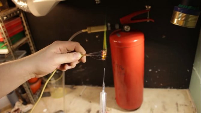
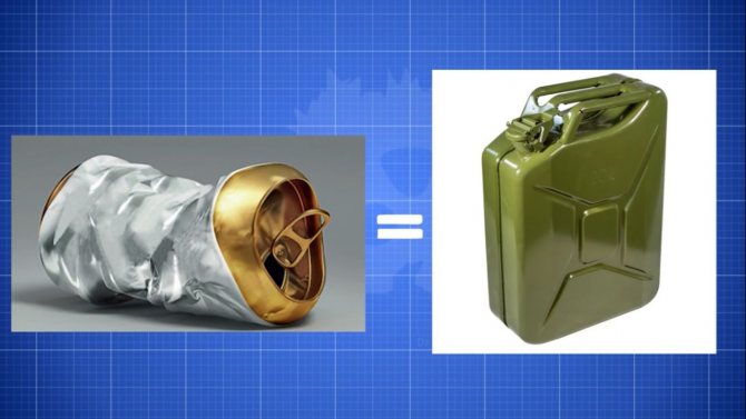
At the beginning of June last year, a hydrogen generator from a fire extinguisher was assembled.
You will learn more about the assembly process by watching the video.
It does a good job of generating hydrogen, but it cannot be used as a gas source for a gas burner. There are two reasons for this. Firstly, there is no normal regulation of the gas supply, and secondly, there is a danger of the flame getting directly into the cylinder. The likelihood that this will happen is, in principle, too vague, but still it cannot be completely ruled out. Therefore, some kind of flame-cutting mechanisms will be required. All this will be described in today's article. Even in several versions.
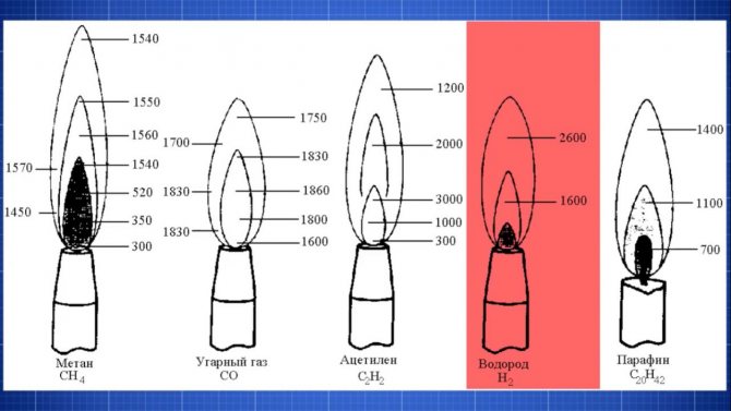
The use of hydrogen as a fuel for gas burners is quite justified. Since the temperature of the hydrogen flame is higher than that of many other gases. Besides, it is very easy to get hydrogen. The production of hydrogen will require aluminum in any available form. You will also need alkali. A kilogram of alkali can be bought for less than 100 rubles.
You can get a lot of hydrogen from it.From a kilogram of sodium alkali (caustic soda), 840 liters of hydrogen are obtained. And from a kilogram of potash alkali, about 600 liters of hydrogen are obtained. Moreover, for every 10 liters of hydrogen, only 8 g of aluminum is required. In short, from one beer aluminum can you get about a canister (20 liters) of hydrogen. And that's cool.
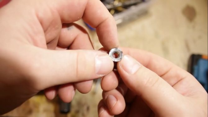
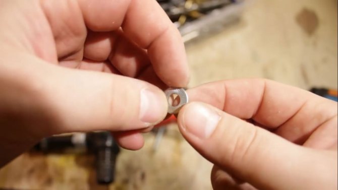
The author decided to adjust the gas supply using a bolt and a pair of nuts. You need to install the bolt at the very edge of the locking and starting device. The farther from the edge, the smoother the adjustment will be. The bolt must be well locked. So that he never gets out at all. Just for such purposes, the author has serrated disc washers and such toothed nuts.

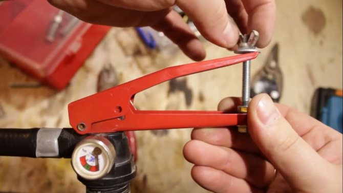
Of course, this does not replace the reducer in any way, but the gas valve can definitely replace it. Now we load all aluminum scraps and unsuccessful castings, other aluminum containing parts and pieces of foil. In short, everything that was nearby.
You can load a lot of aluminum at once. The bigger, the better. But within reasonable limits. Of course, you don't need to stuff to the eyeballs. 100 g of aluminum will be sufficient.
It is easier to regulate the amount of hydrogen produced with alkali. 100 g of potassium lye will produce about 60 liters of hydrogen. If we take into account that a fire extinguisher can quite confidently hold 26 atm, and its free volume is about 6 liters, then no more than 150 liters of hydrogen can be produced in it at a time. It's pretty good.
Water needs to be poured 500 grams, well, or even more. The reaction starts immediately and hydrogen is released. The gases mix very well. The streams of released hot hydrogen and water vapor coming from the surface of the solution pass through the entire volume of the fire extinguisher. At the same time, they mix all the gases that are there.
Initially, 6 liters of air, which were in the cylinder, contained 20% oxygen. But after 60 liters of hydrogen were produced, the volume of gases increased more than 10 times. That is, the oxygen content was already only 2%.
If the hydrogen content in the gas mixture is higher than 75%, then such a mixture is incapable of burning without additional oxygen. And as a result, it is not capable of detonating. That is, it is absolutely explosion-proof. But do not rely only on this, you need to make some kind of reliable flame cutter. The most affordable is, of course, water. We attach a small water tank to the generator body. We make 2 holes in its lid, and pass tubes through them.
The 5 liter plastic bottle will perfectly smooth out the jerks resulting from bursting bubbles. But it must be purged in order to expel oxygen from the container. You will have to lose at least 5 liters of hydrogen, but nothing, all this will be corrected a little later.
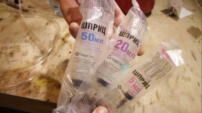
Next, you will need syringes of different sizes. They come with needles with different diameters of 1.2 mm, 0.8 mm and 0.7 mm. If we grind off the sharp part of it, we get good such burners of different capacities. Then the author hooked up a syringe that can be used with different needles.


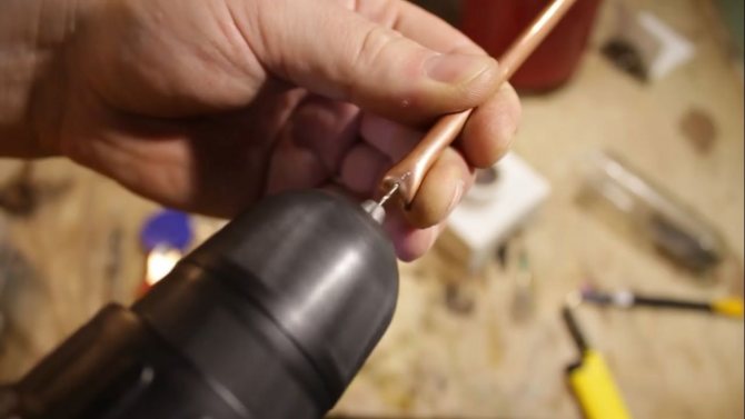
The syringe burner is very inconvenient.You constantly need to hold on to all the parts so that they do not creep out from high pressure. Therefore, the author made just such a copper burner by drilling a hole with a diameter of 1 mm in the tube.
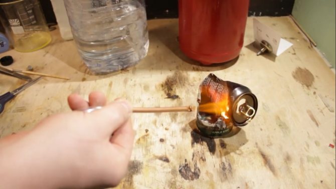
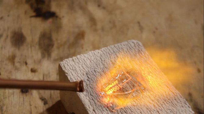
Let's add some destruction. Let's destroy the aluminum can and try to melt a little bit of broken chemical dishes.
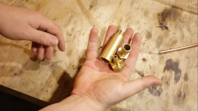
Inside, you need to fill the copper wire as tightly as possible. We will use all the useful space, even stuff it into the fitting.

We will collect threaded connections for paste and tow. Maybe it does not super properly seal, but the pressure in this part of the system will not be too large and it seems that it should not be etched. Tightly-tightly stuff the wire inward in order to fill the inner volume as evenly as possible. You can even use a hammer at the end. But despite this, air still passes through such a flame arrester with little or no effort.

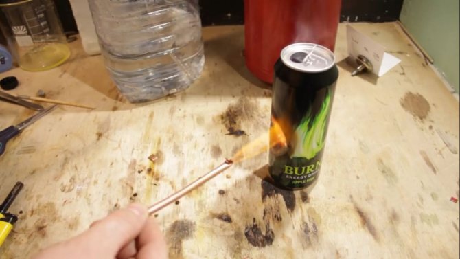
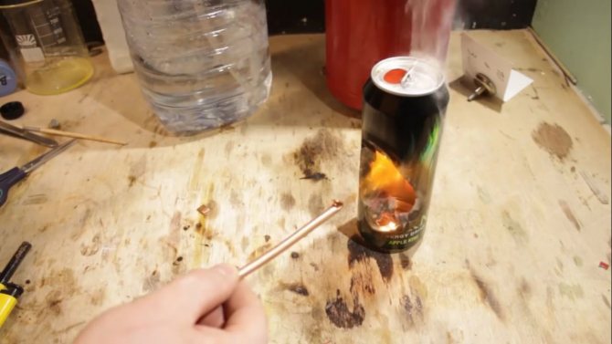
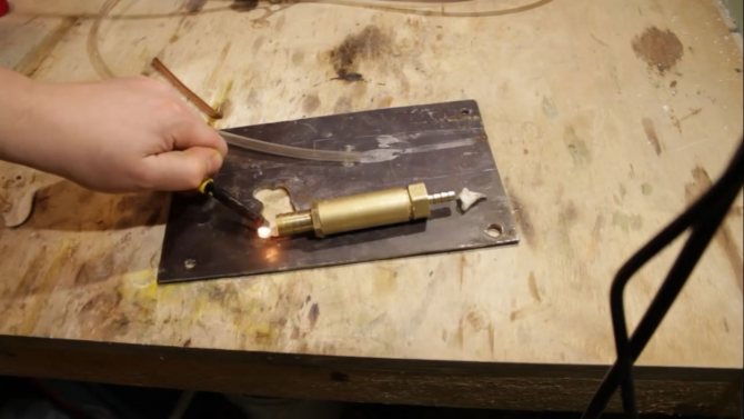
We fasten the last spare part. You need to check it somehow. To do this, the author repeatedly collects hydrogen inside this piece. On one side, he puts cotton wool soaked in acetone. Its vapors flare up from the slightest flame.
If the flame can pass through this extinguisher, then the fleece will ignite. Note that the system is not even pressurized. It will look like just the case when the pressure in the cylinder has dropped to a minimum and there is a great danger of a flame getting inside the cylinder. Periodically, the author himself set fire to the cotton wool to check if the acetone vapor had not completely evaporated. And if necessary, he moistened it again.

Thank you for attention. Until next time!
Video:
Source
Become an author of the site, publish your own articles, descriptions of homemade products with payment per text. More details here.