Characteristics of heating furnaces
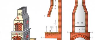
Heating stoves are designed for heating residential premises. Their designs have changed several times; multi-turn heating furnaces with successive vertical smoke flows have been replaced by single-turn heating furnaces with one ascending chimney and several descending ones.
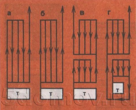
Gas flow patterns in household stoves a - a multi-turn stove with vertical channels; b - single-turn oven; c - stove with upper and lower heating chambers; d - stove with reinforced bottom heating with upper and lower heating chambers
In single-turn ovens, the outer walls are warmed up more evenly. When installing a grate in the firebox of such stoves, the efficiency increases to 70-75%.
The disadvantage of single-turn ovens is that their upper part heats up more than the lower one. Because of this, there is no uniform heating of the premises with a minimum temperature difference at the floor and at the ceiling.
Heating stoves of various sizes and designs with increased bottom heating, given in this article, with their correct operation, ensure uniform heating of premises with a minimum temperature difference at the floor and at the ceiling of 2-3 ° C.
By their design, these ovens consist, as it were, of two ovens, stacked one on top of the other and interconnected by one vertical connecting channel. In heating furnaces of these structures, intensive heating of the lower part of the furnace occurs.
Hot flue gases in the kiln body move as follows. Coming out of the firebox (see Fig. 1), they first warm up the lower part of the stove, then, going up the vertical connecting channel, they warm up the upper part of the stove. In vertical longitudinal and cross sections, arrows show the movement of hot flue gases in individual parts of the furnace body.
In the furnaces of these designs, the flue gases pass the same distance before they exit into the chimney in the course of their general movement in the furnace mass as in single-turn furnaces with one ascending and several descending channels. Flue gases in heating furnaces of this design make a short path, overcoming a small gas resistance. In an array of furnaces of such designs, flue gases move according to the principle of "free" gas movement, as discussed below.
"Free" movement of gases
The heating stoves shown in this article are thick-walled, moderate heating stoves with increased heat transfer from the bottom of them. The heating of these furnaces lasts only 45-60 minutes, the fuel is placed in them in 3-4 steps. Usually, these stoves are heated once a day, but at a low outside temperature (up to 35-40 ° C), it is advisable to heat the stoves twice a day - in the morning and in the evening. With a two-time firebox, a normal temperature in rooms with a daily fluctuation of 2-3 ° C is ensured.
These furnaces are very economical in terms of fuel, their efficiency is especially increased when installing hermetically sealed furnace and blower doors. Fuel costs are reduced by half or more compared to the operation of multi-turn furnaces. It is advisable to use anthracite as a fuel, and in its absence, you can use coal, coal briquette, peat briquette and any firewood. When harvesting firewood, the length of the logs must be made according to the dimensions of the firebox of the stove.
Below is a detailed procedure for laying a 770 × 640 mm heating stove. The masonry of the rest of the heating stoves is basically similar to the masonry of the above-mentioned stove, therefore, their masonry will be described more succinctly.
Choosing a furnace model
If there is a sufficient amount of theoretical and practical material on a narrow topic in the field of construction, few will miss the opportunity to save a certain amount of money and do the work on their own, because a brick-built cooking stove with their own hands eliminates the payment for the work of the master.
The construction of a furnace is a time-consuming and energy-consuming process. Everything is complicated by the preparatory stage, at which it is necessary to make calculations of the main parameters, determine the choice of the furnace model, and get acquainted with the project of this model.
Undoubtedly, the best practices from professional craftsmen make the tasks of self-construction much easier. All parameters, drawings, diagrams of various models are collected in a single document called a project. The novice wizard can only choose the most suitable projects for their tasks and use ready-made standard calculations. But even the choice of a finished model should be made on the basis of some criteria, and not spontaneously, as many people who have never come across such a question as heating stoves think.
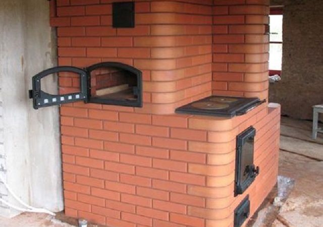
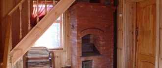
Stove ready to start
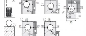
Despite the fact that technical calculations are more related to the firebox and chimney, it is necessary to assess the dimensions of the furnace itself and the dimensions of the room in which it is planned to be installed. Bulky brick ovens for a home with a hob in a small room will look ridiculous. And the heating process will not become more efficient from this, because in order to heat a large structure, it will have to be heated longer. The size ratio can be found in Runet along with the project.
Good to know: A stove-fireplace for a summer residence, choose between a brick and cast-iron option
The location of the stove will influence the choice of model. Ovens with a hob should be oriented so that cooking units open into the kitchen and the back and side walls heat adjacent rooms. But this is just practical advice and the owner has the right to choose where to fold the stove.
The ordinal masonry scheme presented in the project will allow the construction of one of three options for stoves: T-shaped, square or rectangular. The T-shaped device is installed in the center of the room, partially producing its zoning. It efficiently heats several rooms at once. This principle was implemented in peasant huts. First, a stove for the house was built, and then the frame itself was erected.
T-shaped version
The other two types can serve as island or wall models.
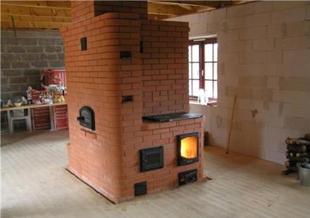
Stove ready for use
The compact oven does not take up much space while being an efficient heat source. This model is designed specifically for summer cottages and small country houses. It allows you to warm up the room, adapting it for long-term living in the winter.
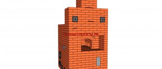
Heating stove with bottom heating, size 770 × 640 mm
The heating stove has dimensions, mm: 770x640x2310 (Fig. 1, a).
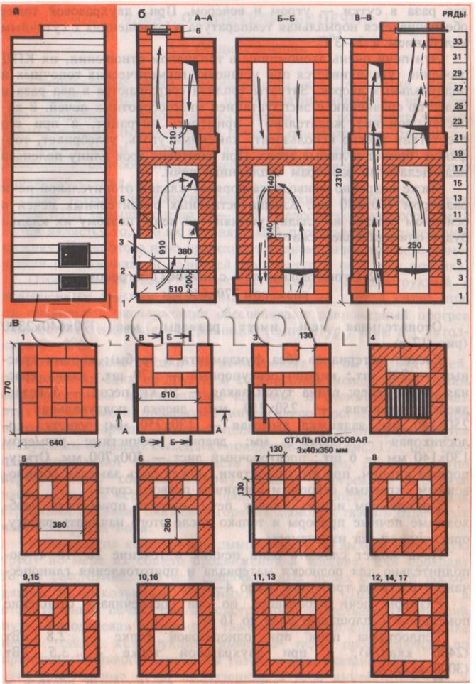
Fig. 1. Heating stove with bottom heating measuring 770 × 640 mm a - facade; b - sections A — A, B — B, B — C; c - masonry 1–17 rows; 1 - ash pan; 2 - blower door; 3 - grate; 4 - furnace door; 5 - firebox; 6 - smoke damper.
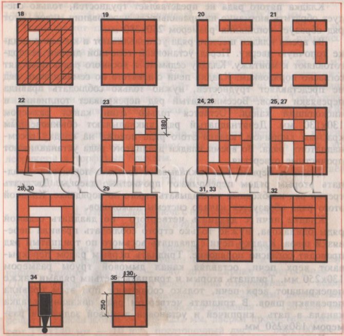
Fig. 1. Continuation: d - laying 18-35 rows
Material consumption (without foundation and pipe):
- red brick - 220 pcs.;
- refractory bricks - 170 pcs.;
- red clay - 10 buckets;
- refractory clay - 50 kg;
- sand - 5 buckets;
- furnace door - 250 × 210 mm;
- blower door - 250 × 140 mm;
- smoke valve - 130 × 250 mm;
- grate grate - 380 × 250 mm;
- cleaning doors with dimensions 130 × 140 mm - 6 pcs .;
- pre-furnace sheet - 500 × 700 mm.
Refractory bricks, in their absence, can be replaced by ordinary red selective bricks of the first grade.
Before you start laying the stove, you should purchase the necessary stove appliances and only then start work, focusing on their size.
The stove can be folded by one stove-maker within 16-18 hours; additionally, it takes about 4-5 hours to bring the material and prepare the clay-sand mortar.
The dimensions of the stove are small, but it provides heating for a room with a floor area of up to 16 m². The heat transfer of the stove with a disposable firebox is 2.8 kW (2400 kcal / h), and with a two-time firebox - 3.5 kW (3000 kcal / h).
The stove has a simple design, increased heating in the lower zone, anthracite, coal, coal briquettes, peat briquettes, and firewood serve as fuel. Hot flue gases in the furnace move through a well-developed chimney system, while heating its inner walls.
In fig. 1, b, vertical sections of the furnace are given along A — A, B — B and C — C, and the orders show in what sequence the laying of bricks and the installation of oven devices in each row are carried out.
The vertical sections show the firebox 1, the ash-pan 2, the grate 3, the furnace door 4, the blower door 5, the smoke valve 6, cleaning holes.
The arrows indicate the directions of movement of hot flue gases in the heating furnace, and the dashed lines show the movement of cold room air in the heated furnace before the complete closure of the smoke damper.
Hot flue gases of the warming-up stove from the firebox rise up to the firebox overlap and from the upper opening.
Masonry fifth row does not present difficulties, only you should pay attention to the correctness of the alternation of the seams. This row forms a firebox measuring 250 × 380 mm.
During masonry sixth row install and attach the fire door to the masonry. Before installing the combustion door, it is prepared for installation. Masonry seventh and eighth rows carried out according to the orders. Furnace masonry from the ninth to the seventeenth row does not present difficulties, you just need to follow the rules for bandaging the seams. Eighteenth row blocks the firebox and the descending channel. Only one channel of 130 × 130 mm remains. Nineteenth row they are laid out with ordinary red bricks, the laying of this row is similar to that of the eighteenth row. During masonry of the twentieth row, clean-out holes are installed.
Twenty-first row spread according to the order. Twenty-second nearby block the cleaning doors. Twenty-third row must be laid out strictly in order. The masonry of this row forms the beginning of the chimney system.
Furnace masonry from twenty-fourth to twenty-seventh rows is the same, you just need to strictly follow the rules for bandaging the seams. Furnace masonry from the twenty-eighth to the thirtieth row carried out according to the order. Thirty-first row cover the top of the furnace, leaving a chimney channel 130 × 250 mm in size. Thirty-second and thirty-third rows also overlap the top of the oven, only observe the rules for bandaging the seams. In the thirty-fourth row the masonry is shown (a channel of five bricks and the installation of a smoke damper with a size of 130 × 250 mm.
Masonry thirty-fifth row the chimney begins. Pipe laying is not difficult. The pipe is laid out "five", in detail observing the rules for dressing the seams, with an internal pipe size of 130 × 250 mm strictly vertically. When passing through the ceiling and roof, fire-prevention measures must be observed. After finishing the laying of the stove and chimney, they are dried with test furnaces, after drying they are plastered and whitewashed.
Some roots - different sprouts
Considering the heating and cooking stoves, we note that the ordering is similar to the layout of the Russian stove with individual elements of the fireplace. This is not surprising, because the stoves used in our country have only a Western name - "Swede", and they are adapted primarily for use in an ordinary Russian hut.
To build a stove with our own hands, we need to order brick stoves for the house. In addition to the ordering of heating and cooking stoves, we will naturally need materials.We will not focus on this, since on the pages of our Internet resource it is written in sufficient detail about choosing a brick for laying stoves and fireplaces with our own hands, preparing solutions for stoves, making a stove foundation.
Standard oven order:
- Row -1 is the most important. The bricks are laid with their own hands strictly according to the level, the control of the angles is measured using a construction square.
- Our heating and cooking stove has a blower located, the order shows that in front of it, in the front of the stove, a three-quarter brick is used. For convenient ash removal, the inner sides of the bricks are tucked under a cone towards the direction of the chamber.
1st row
- The blower door is installed and laying of the 2nd row begins.
2nd row
- The heating cooking stove in the 3rd row is placed as indicated by the order. The blower configuration is achieved by cutting off both sides of the brick. The height of the row is the same as the height of the door.
3rd row
- 4th row. Begins to give all the best on the left side. First, the cleaning door is installed. Do-it-yourself masonry is performed in order, while the blower door is blocked. The hole above the ash pan is made in a square shape. This is achieved by chipping off the brick.
4th row
- In the 5th row, the ash pan opening narrows even more. The whole row is very similar to the 4th one.
5th row
- For the 6th row, a refractory brick will be required, the place of laying of which is indicated by hatching in the order. But if there is no refractory brick, you can use ordinary brick. The brick in front of the grate is chipped off. This ensures better placement of the fuel on the grate. The grille itself rests on the 5th row.
- Do not forget to leave a gap between the 6th row bricks and the grate within 10-15 mm. The gap is filled with ash or sand, it compensates for the expansion of the metal of the grate when heated.
6th row
- 7th row. The U-shaped channel is closed in such a way that three new channels are formed. A combustion chamber door is installed, which rests on the 6th row.
7th row
- The 8th and 9th rows are identical to the 7th. The height of the 9th row is at the same height as the combustion chamber door. Bricks of the 9th row, overlapping the partition of the combustion chamber and the left channel, are constrained on both sides for a smooth transition of flue gases from the furnace to the channel.
8th row
9th row
- The 10th row is made of refractory bricks. The entire row is carried out strictly vertically with a building level control. This is done because the order in which heating cooking stoves are arranged obliges to lay a cooking floor on them.
- The furnace door closes. In this row, only two channels remain, strictly square in cross section.
10th row
- The 11th row is made of ordinary brick. The cooking floor covers the combustion chamber. On the left, there are two channels with a square cross section. The edge of the brick in contact with the cooking deck is cut in such a way that a gap of 20 mm is formed between them. The flooring itself rests on the 10th row. Here you can install a large door for the cooking chamber. In this case, if necessary, it can be successfully used as an oven. It is best to install a metal frame and make a separate damper. Everything is up to you. The heating stove does not have this element, its order is different.
11th row
- The 12th row is stacked according to the order. The two left square channels are connected into one rectangular one.
12th row
- 13th row: the rectangular duct is overlapped in such a way that again two ducts with a square cross section are formed.
13th row
- The 14th row is similar to the 13th. A shutter is installed in it, allowing you to use the hob without heating the entire oven. It is very convenient in the summer. This arrangement with an open damper allows the unit to work like a conventional heating stove.
14th row
- In the 15th row, the valve is closed.
15th row
- 16th row. The cooking chamber door is closed. The door is mounted on the left.It acts as a ventilation system for the cooking compartment and serves to remove odors, steam and fumes during cooking.
16th row
- In the 17th row, the ventilation door is closed. The laying is carried out according to the order. Above, above the cooking chamber, steel strips are laid. In the future, with their help, the cooking chamber will be closed. The order of the heating furnace in most cases does not imply such an overlap, a dome-shaped scheme is usually performed there. But here the requirements are somewhat different.
17th row
- In the 18th and 19th row, the cooking chamber overlaps. On the left, there are two channels with a square cross section.
18th row
19th row
- 20th row. Only one channel with a square section remains on the left. A door is installed for a samovar pipe and for cleaning. Two bricks are installed on the covered surface of the cooking chamber. At the same time, they fit on the edge. The distance from the back wall to the laid bricks must be 40 mm.
20th row
- The 21st row fits in the same way as the 20th.
21st row
- 22nd row. All installed doors overlap. On the left, two channels with a square cross section are again formed. Three longitudinal channels are formed above the cooking chamber. The middle one is 50 mm wide, the outermost ones are 110 mm wide.
- In the 23rd row, the left square channels remain. The long channels above the cooking chamber overlap across. The brick is placed on the edge at a distance, as in the 20th row.
23rd row
24th row
- Rows 25 and 26 are performed in the same way as 22nd.
25th row
26th row
- 27th row. Three bricks are installed on the ribs, installed at the same distance from each other and from the walls of the furnace. Again, there is only one channel with a square cross section.
27th row
- The 28th row is identical to the 27th. Pay close attention to the dressing of the stitches.
28th row
- Row 29. On the left is one channel with a square section. Lay a couple of bricks on the front side. They are laid close to the front wall, recessed to half their thickness and rest on bricks laid on the edge.
29th row
- In the 30th row, the thermal chamber is completely covered. There remains one smoke channel in which the valve is installed.
30th row
- Rows 31 and 32 are performed according to the order. Thus, three rows are formed above the heat chamber, thus providing excellent fire safety.
31st row
32nd row
The stove is ready, now it needs to be decorated, how to do it? Our article Decorating ovens will help you. When finishing with your own hands, make sure that the chosen option matches the interior of the house.
An important part of any stove for the home is a chimney, we recommend reading about which chimney to choose in the article Choosing a Chimney. All subsequent rows form a pipe with a smoke channel. Observe the dressing of the sutures.
1. Ordering - heating and cooking oven
2. Ordering - heating and cooking stove
3. Ordering - heating and cooking oven
4. Ordering - heating and cooking stove
5. Ordering - heating and cooking stove
Heating stove with bottom heating, size 770 × 770 mm
The heating stove has dimensions, mm: 770x770x2310 (see Fig. 2).
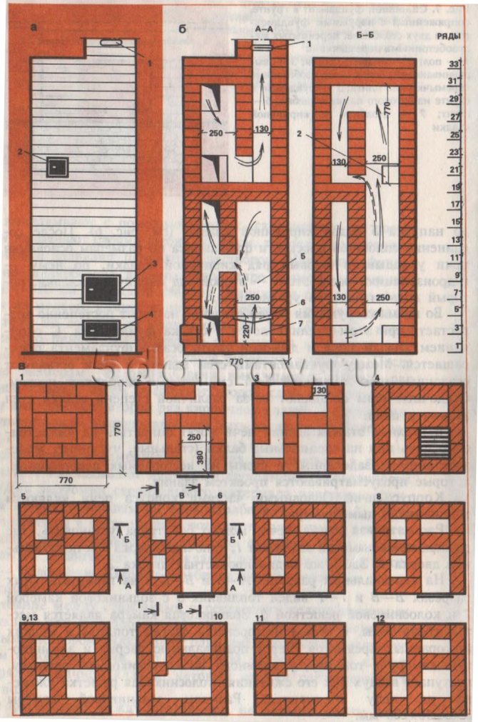
Fig. 2. Heating stove with bottom heating measuring 770 × 770 mm a - facade; b - sections A-A, B-B; c - masonry 1-13 rows; d - sections B — B, G — G; e - masonry 14-35 rows; 1 - smoke valve; 2 - holes for cleaning; 3 - furnace door; 4 - blower door; 5 - firebox; 6 - grate; 7 - ash pan
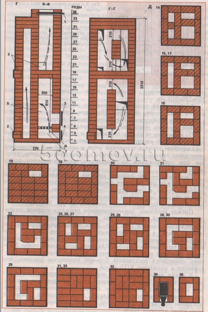
Fig. 2. Heating stove with bottom heating measuring 770 × 770 mm g - sections V — B, G — G; e - masonry 14-35 rows; 1 - smoke valve; 2 - holes for cleaning; 3 - furnace door; 4 - blower door; 5 - firebox; 6 - grate; 7 - ash pan
The material consumption (excluding the foundation and pipe) is as follows:
- red brick - 230 pcs,
- refractory bricks - 210 pcs.,
- red clay - 12 buckets,
- refractory clay - 6 buckets,
- sand - 7 buckets,
- furnace door - 250 × 210 mm,
- blower door - 250 × 140 mm,
- smoke valve - 130 × 250 mm,
- grate grate - 300 × 252 mm,
- cleaning doors with dimensions 130 × 140 mm - 6 pcs.,
- pre-furnace sheet - 500 × 700 mm.
The stove can be folded by one stove-maker within 18-20 hours; additionally, it takes about 5 hours to raise the material and prepare the clay-sand mortar.
The stove is designed to heat a room up to 20 m². The heat transfer of the stove with a one-time firebox (with a consumption of anthracite up to 12.2 kg) is about 3 kW (2600 kcal / h). The heat transfer from the bottom of the furnace is 2.3 kW (2000 kcal / h). The heat transfer of the stove with a two-time firebox increases to 3.7 kW (3200 kcal / h).
It is advisable to use anthracite and coal as fuel, but if they are not available, you can use firewood, coal briquettes and peat briquettes.
The brickwork of the stove in rows does not differ from the previous heating stove measuring 770 × 640 mm.
Heating stove with bottom heating, size 890 × 890 mm
The heating stove has dimensions, mm: 890x890x2310.
The material consumption (excluding the foundation and pipe) is as follows:
- red brick - 340 pcs.,
- refractory bricks - 270 pcs.,
- red clay - 16 buckets,
- refractory clay - 7 buckets,
- sand - 10 buckets,
- furnace door - 250 × 210 mm,
- blower door - 250 × 140 mm,
- smoke valve - 130 × 250 mm,
- grate grate - 380-252 mm,
- cleaning doors with dimensions 130 × 140 mm - 10 pcs.,
- pre-furnace sheet - 500 × 700 mm.
The stove can be folded by one stove-maker within 24 hours; additionally, it takes about 6 hours to bring the material and prepare the clay-sand mortar.
The stove is designed to heat a room with an area of up to 25-30 m. The heat transfer of the stove with a one-time firebox is about 3.7 kW (3200 kcal / h), and with a two-time firebox - 4.7 kW, (4000 kcal / h). Drawings of the furnace sections and masonry ordering are shown in Fig. 3.
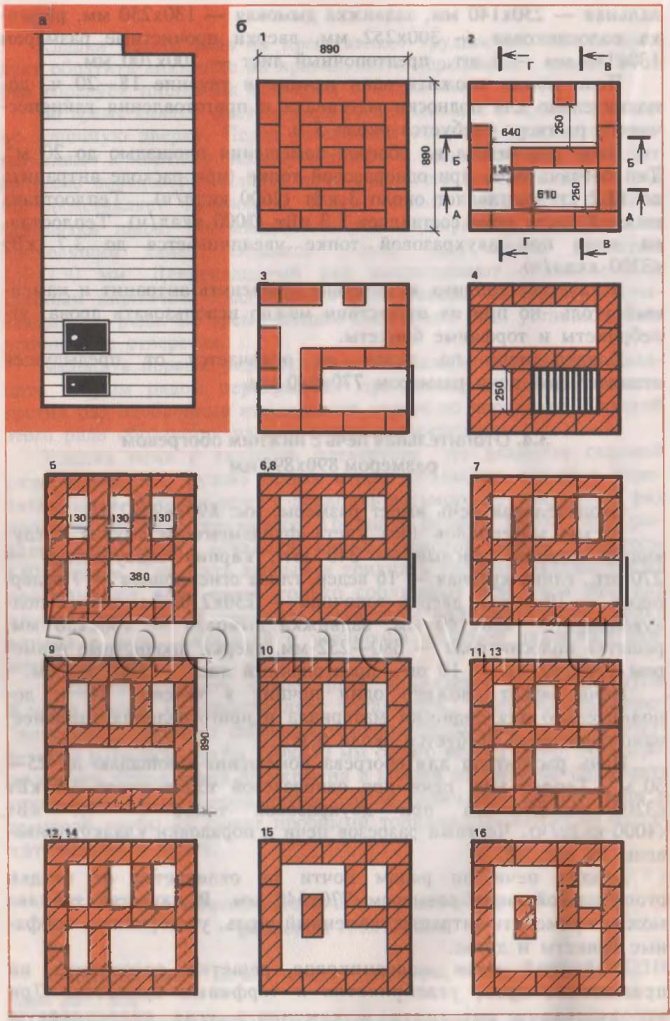
Fig. 3. Heating stove with bottom heating measuring 890 × 890 mm a - facade; b - masonry 1-16 rows;
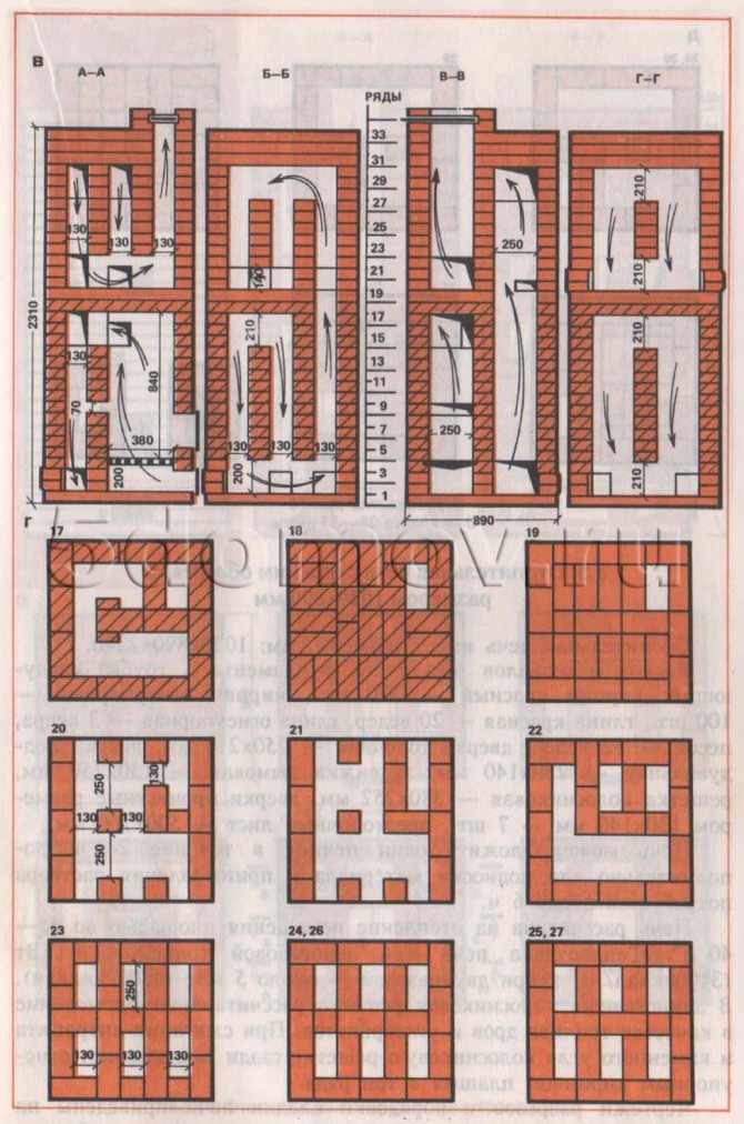
Fig. 3. Continuation c - sections A — A, B — B, C — C, G — G; d - 17 - 27 rows
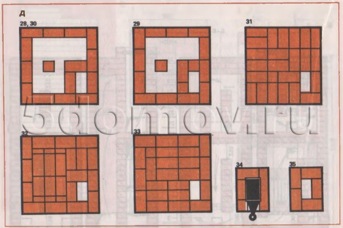
Fig. 3. Continuation d - laying 28-35 rows
The masonry of the stove in rows is almost the same as the masonry of a heating stove measuring 770 × 640 mm. Anthracite, coal, coal briquettes, peat briquettes and firewood can be used as fuel. In this oven, the grate is designed to use firewood, coal briquettes and peat briquettes. When using anthracite and coal, the grate is laid flat behind with three rows of refractory bricks.
Dutch, Swedish - who is who
Differences
Stoves, which are designed for home heating and cooking, have long been called "Swede". In some areas, you can find heating cooking stoves, which are called "Dutch". This is not entirely true. The Dutch woman was usually used in huts as an addition to the Russian stove and was intended to heat the house.
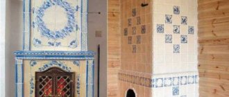
Of course, there were separate options for installing cast iron hobs, but these were mainly intended for heating rather than for basic cooking. Dutch women, as a rule, were decorated with tiles, this is a kind of "fashionista" of the Russian hut.
The order of the stove is also different: the Dutch heating stove does not imply the installation of the hob, as in the Russian stove.
"Shvedka", like the Russian stove, is a workhorse that performs several functions at once. You can successfully cook food on it, it is able to provide the house with heat, and some options allow you to use it as an oven, bake bread and more.
Today we will tell you about the device with our own hands of just such an option. Before us are the drawings and the ordering of the heating and cooking furnace.
Heating Cooking Oven - Ordering
Heating stove with bottom heating, size 1020 × 890 mm
The heating stove has dimensions, mm: 1020x890x2240.
The material consumption (excluding the foundation and pipe) is as follows:
- red brick - 570 pcs.,
- refractory bricks - 100 pcs.,
- red clay - 20 buckets,
- refractory clay - 3 buckets,
- sand - 12 buckets,
- furnace door - 250 × 210 mm,
- blower door - 250 × 140 mm,
- smoke valve - 130 × 250 mm,
- grate grate - 380 × 252 mm,
- cleaning doors with dimensions 130 × 140 mm - 7 pcs.,
- pre-furnace sheet - 500 × 700 mm.
The oven can be folded by one stove-maker within 24 hours, in addition, it will take about 6 hours to bring the material and prepare the solution.
The stove is designed to heat a room up to 35-40 m². The heat transfer of the stove with a one-time firebox is 4 kW (3400 kcal / h), and with a two-time one - about 5 kW (4300 kcal / h).
In this stove, the grate is designed to use firewood and coal briquettes as fuel. When burning anthracite and coal, the grate is laid in the back with refractory bricks flat in three rows.
Drawings of sections and orders of the furnace masonry are shown in Fig. 4. The laying of the stove is carried out according to the order, observing the rules for bandaging the seams.
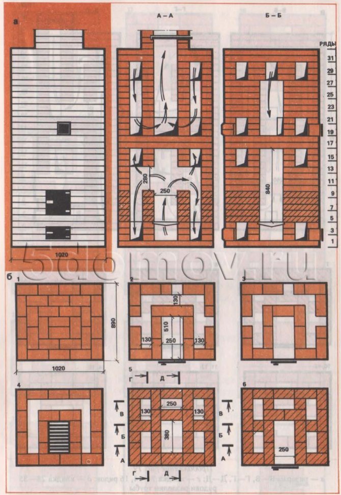
Fig. 4. Heating stove measuring 890 × 1020 mm a - facade and sections A — A, B — B; b - masonry 1-6 rows
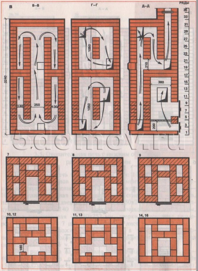
Fig. 4. Continuation in - sections V — V, G — G, D — D; d - laying 7-14, 16 rows
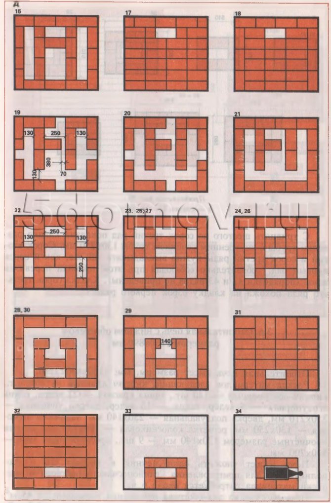
Fig. 4. Continuation d - laying 15, 17-34 rows and pipe cutting
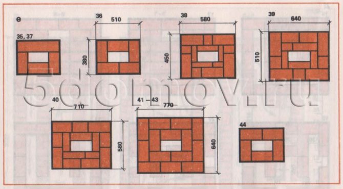
Fig. 4. Continuation e - laying 35-44 rows
From the thirty-sixth to the forty-third row, the laying of a pipe cut with an internal pipe section of 130 × 250 mm is shown. The forty-second and forty-third rows must be laid out in the same way as the forty-first row, while always observing the rules for dressing the seams (orders 42 and 43 are not shown). The laying of the forty-third row is similar to the laying of the forty-first row.
Heating stove with bottom heating, size 1160 × 890 mm
The heating stove has dimensions, mm: 1160x890x2240.
The material consumption is as follows:
- red brick - 580 pcs.,
- refractory bricks - 140 pcs.,
- red clay - 22 buckets,
- refractory clay - 5 buckets,
- sand - 13 buckets,
- furnace door - 250 × 210 mm,
- blower door - 250 × 140 mm,
- smoke valve - 130 × 250 mm,
- grate grate - 380 × 252 mm,
- cleaning doors with dimensions 130 × 140 mm - 9 pcs.,
- pre-furnace sheet - 500 × 700 mm.
The stove can be folded by one stove-maker within 26 hours; in addition, it will take about 6 hours to prepare the clay-sand mortar and to bring the material.
The stove is designed to heat a room up to 45 m. The heat transfer of the stove with a one-time firebox is 4.3 kW (3700 kcal / h), and with a two-time firebox - 5.4 kW (4600 kcal / h).
In this furnace, the grate is designed to use firewood, coal briquettes and peat briquettes as fuel. When using anthracite and coal, the grate is laid at the back with refractory bricks on the edge.
Drawings of sections and ordering of masonry are shown in Fig. five.
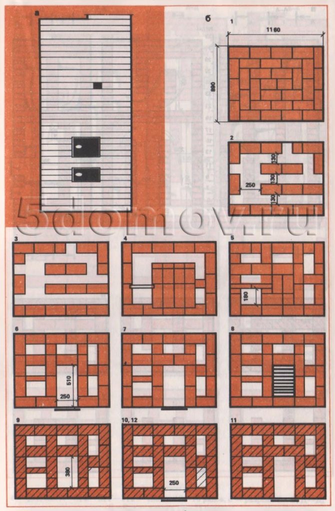
Fig. 5. Heating stove with bottom heating, size 1160 × 890 mm a - facade; b - laying 1-12 rows
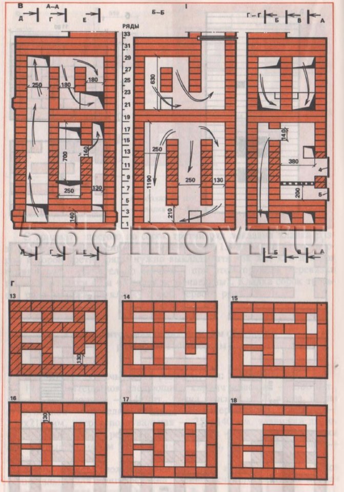
Fig. 5. Continuation c - sections A — A, B — B, G — G; d - masonry 13-18 rows
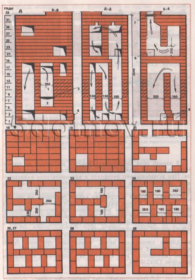
Fig. 5. Continuation d - sections B — B, D — D, E — E; f - masonry 19-28 rows; 1 - firebox; 2 - ash pan; 3 - grate; 4 - furnace door; 5 - blower door; 6 - cleaning holes; 7 - smoke valve
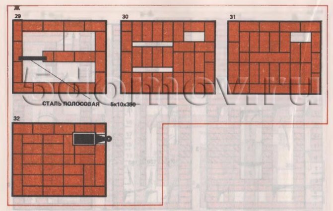
Fig. 5. Continuation g - laying 29-32 rows
When laying the second row, it is necessary to strictly adhere to the order, since this row forms the chimney system of the lower heating chamber. Masonry of the fourth and fifth rows' arrange the bottom of the ash pan. When laying the sixth row, a blower door is attached to the masonry.
Otherwise, the laying of the stove does not present difficulties and is similar to the laying of previous stoves, only it is necessary to strictly adhere to the procedures: you should not make unjustified narrowing of the chimneys. The pipe is placed in five bricks with an internal dimension of 130 × 250 mm.
Heating stove with bottom heating, size 1290 × 510 mm
The heating stove has dimensions, mm: 1290x510x2310 (see Fig. 6).
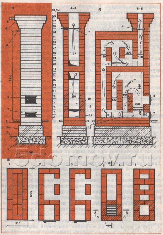
Fig. 6. Heating stove with dimensions 510 × 1290 mm a - facade; b - sections A — A; c - masonry 1 - 5 rows; 1 - foundation in the ground; 2 - soil; 3 - smoke valve; 4 - cutting; 5 - ceiling slab; 6 - furnace door; 7 - blower door; 8 - waterproofing; 9 - external foundation; 10 - firebox; 11 - ash pan; 12 - grate; 13 - holes for cleaning
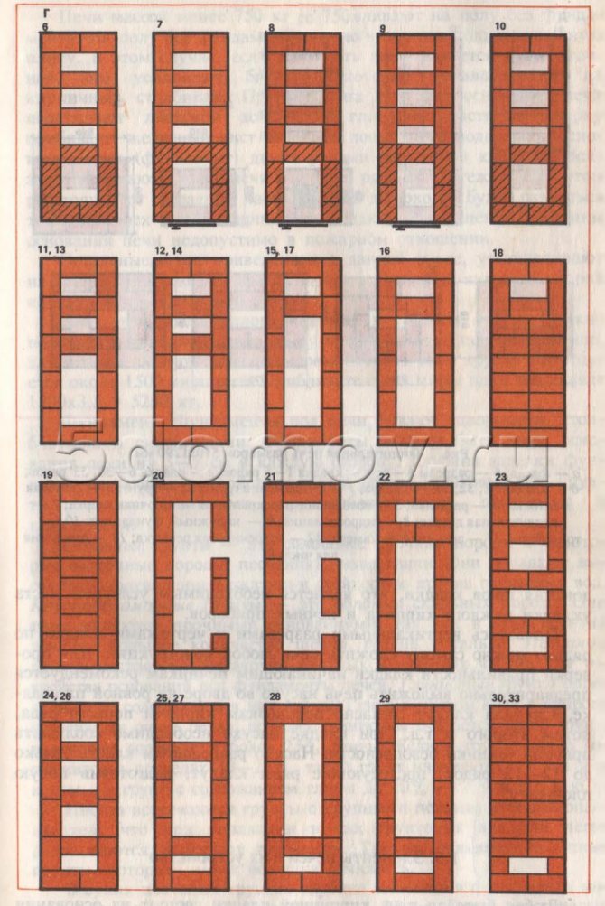
Fig. 6. Continuation d - laying 6-30, 33 rows
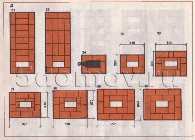
Fig. 6. Continuation d - laying 31.32, 34-40 rows
Material consumption (without foundation and pipe) is as follows:
- red brick - 400 pieces,
- refractory bricks - 220 pcs.,
- red clay - 16 buckets,
- refractory clay - 10 buckets,
- sand - 11 buckets,
- furnace door - 250 × 210 mm.,
- blower door - 250 × 140 mm,
- smoke valve 130 × 250 mm,
- grate grate - 300 × 250 mm,
- cleaning doors with dimensions 130 × 140 mm - 4 pcs.,
- pre-furnace sheet - 550 × 700 mm.
The stove can be folded by one stove-maker within 24 hours; in addition, it will take about 6 hours to prepare the solution and bring the material.
The heat output of the stove with a one-time firebox is about 3.8 kW (3300 kcal / h), with a two-time firebox - 5.1 kW 14 400 kcal / h) ^ The stove is designed to heat a room with an area of up to 35 m. It is advisable to lay the furnace from the fourth to the eighteenth row from refractory bricks. With proper operation, the efficiency of this furnace can be up to 80%, and with the use of sealed (furnace and blower) doors it reaches 85%.
The laying of the stove is simple, it is carried out according to the orders, while observing the correct alternation of the seams.
Heating stove with bottom heating, size 1650 × 510 mm
The heating stove has dimensions, mm: 1650x510x2310.
Material consumption (excluding the foundation and chimney) is as follows:
- red brick - 640 pcs.,
- red clay - 22 buckets,
- sand - 12 buckets,
- furnace door - 250 × 210 mm,
- blower door - 140 × 250 mm,
- smoke valve - 130 × 250 mm,
- grate grate - 300 × 250 mm,
- cleaning doors with dimensions 130 × 140 mm - 7 pcs.,
- pre-furnace sheet - 500 × 700 mm.
The stove can be folded by one stove-maker within 26 hours; in addition, it will take about 6 hours to prepare the clay-sand mortar and to bring the material. 2
The stove is designed to heat a room with an area of up to 50 m. The heat output of the stove with a one-time firebox is 5 kW (4300 kcal / h), with two fireboxes per day - about 6.2 kW (5300 kcal / h). All types of solid fuel can be used in this stove, but when using anthracite and coal, it is advisable to lay out the stove from the ninth row to the firebox overlap with refractory bricks, and in its absence, lay out the firebox using selected red bricks in these rows.
Drawings of sections and ordering are shown in Fig. 7.
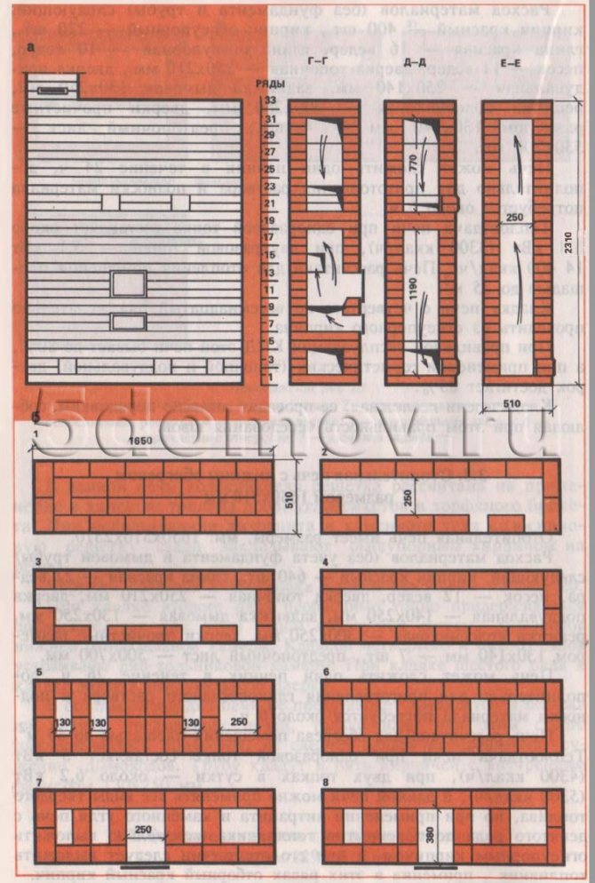
Fig. 7. Heating stove with bottom heating, size 1650 × 510 mm a - facade and sections G — G, D — D, E — E; b - masonry 1-8 rows
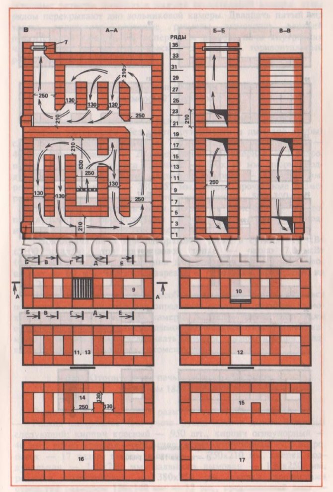
Fig. 7. Continuation c - sections A — A, B — B, B — C; d - laying 9-17 rows
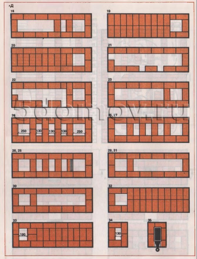
Fig. 7. Continuation d - laying 18-35 rows
The laying of the stove is not particularly difficult. The fifth row determines the main dimensions of the chimneys of the lower heating chamber; this row covers the bottom of the ash pan. The twenty-fifth row also defines the main dimensions of the chimneys of the upper heating chamber. In a cross-section of the furnace, the interior is visible, as in an X-ray photograph (see the horizontal section of the furnace).
Stove with heat shield
This design is an improvement on a simple hob, which consists in connecting a heating shield to it. Furnace gases are discharged into it. The shield itself is a small side wall with chimneys inside. The still rather hot oven gases from the hob give off a significant part of the heat in these channels before going out into the chimney. This increases the efficiency of the entire structure.
1. The occupied area is largely determined by the size of the cast-iron stove, which overlaps the firebox. In addition, the chimney takes up some space. Replacing this pipe with a heating plate increases the occupied area slightly.
2. I provide summer and winter options for the firebox in the shields. In the summer version, only a small part of the flap is heated. When the firebox is heated in winter, the entire flap is heated.
3. The hob and heating plate can be built independently of each other. Those who want to try themselves in the construction of stoves can use this fact and take on the job more boldly. Indeed, in case of failure, it will not be so annoying to go back, to disassemble the failed building.
So uncomplicated brick heating cooking stove defines its features:
- low cost;
- erection in a short time;
- small footprint.
The flip side of simplicity means the lack of some of the useful properties that are inherent in more complex designs.
Heating stove with bottom heating, size 2250 × 510 mm
The heating stove has dimensions, mm: 2250x510x2480.
Material consumption (excluding the foundation and chimney) is as follows:
- red brick - 740 pcs.,
- refractory bricks - 40 pcs.,
- red clay - 25 buckets,
- refractory clay - 1 bucket,
- sand - 15 buckets,
- furnace door - 250 × 210 mm,
- blower door - 250 × 140 mm,
- smoke valve - 130 × 250 mm,
- grate grate - 380 × 252 mm,
- cleaning doors with dimensions 130 × 140 mm - 7 pcs.,
- pre-furnace sheet - 500 × 700 mm.
The stove can be folded by one stove-maker within 30 hours; in addition, it will take about 8 hours to prepare the clay-sand mortar and the materials to be brought in.
The heat output of the stove with a one-time firebox per day is 6 kW (5100 kcal / h), with a two-time firebox - about 7.1 kW (6100 kcal / h). The stove is designed to heat a room up to 60 m². Drawings of sections and ordering are shown in Fig. eight.
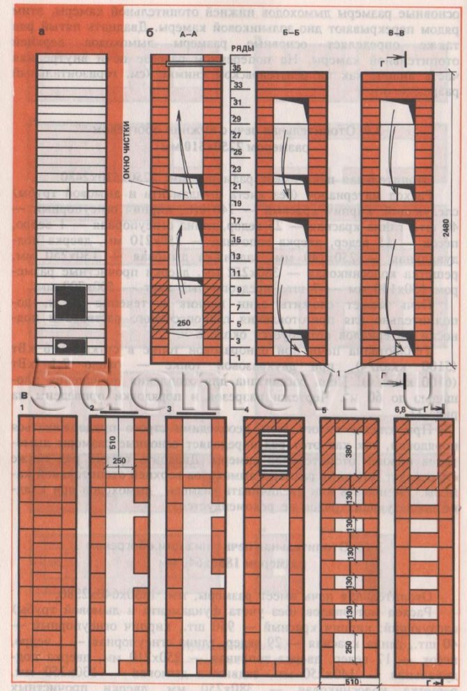
Fig. 8. Heating stove with bottom heating, size 2250 × 510 mm a - facade; b - sections A — A, B — B, B — C; c - masonry 1-6, 8 rows
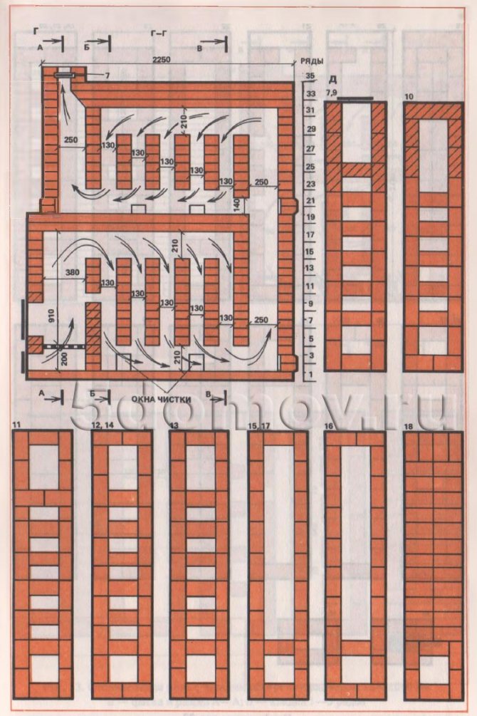
Fig. 8. Heating stove with bottom heating, size 2250 × 510 mm g - section G — G; d - laying 7 - 18 rows
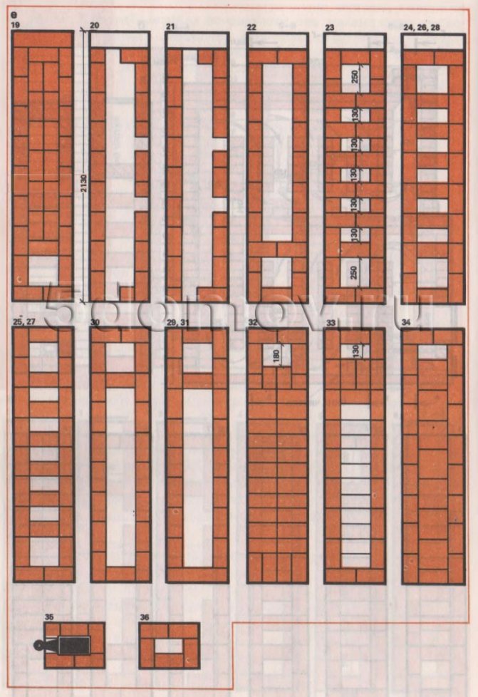
Fig. 8. Heating stove with bottom heating, size 2250 × 510 mm e - masonry 19-36 rows
When laying the fifth row, it is necessary to strictly adhere to the order, since this row determines the main dimensions of the chimneys of the lower heating chamber. The twenty-third row also defines the main dimensions of the chimneys of the upper heating chamber. It is not recommended to reduce or increase the size of chimneys when laying subsequent rows.
Heating stove with bottom heating, size 1880 × 640 mm
The heating stove has dimensions, mm: 1880x640x2380.
Material consumption (excluding the foundation and chimney) is as follows:
- red brick - 950 pcs.,
- refractory bricks - 40 pcs.,
- red clay - 29 buckets,
- refractory clay - 1 bucket,
- sand - 17 buckets,
- furnace door - 250 × 210 mm,
- blower door - 140 × 250 mm,
- smoke valve - 130 × 250 mm,
- grate grate - 380 × 250 mm,
- cleaning hole doors 130 × 140 mm - 12 pcs.,
- pre-furnace sheet - 500 × 700 mm.
The stove can be folded by one stove-maker within 36 hours; additionally, it will take about 10 hours to prepare the solution and apply the material.
The heat output of the stove with a disposable firebox per day is about 5.5 kW (4700 kcal / h), with two fireboxes - 6.6 kW (5700 kcal / h). ^ The stove is designed to heat a room with an area of up to 55 m. All types of solid fuels can be used in this furnace. The grate is designed for using firewood, coal briquettes and peat briquettes as fuel. When using anthracite or coal as fuel in this furnace, the grate is laid with refractory bricks on the edge.
Drawings of sections of the furnace and ordering are shown in Fig. 9. Arrows indicate the movement of flue gases in the chimneys of the furnace.
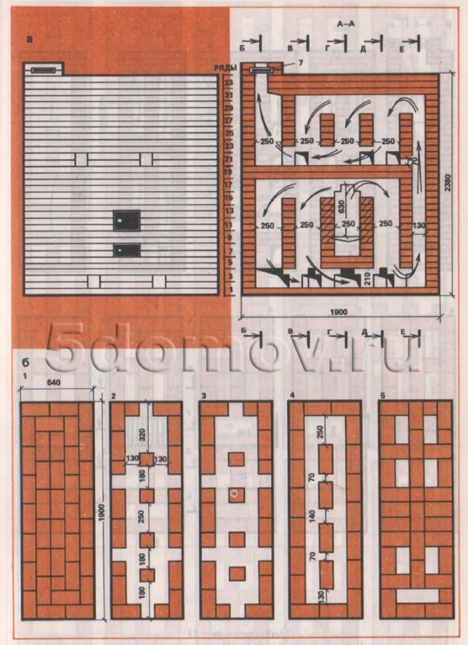
Fig. 9. Heating stove with bottom heating, size 1880 × 640 mm a - facade and section A — A; b - masonry 1-5 rows
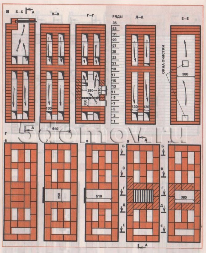
Fig. 9. Heating stove with bottom heating 1880 × 640 mm in size - sections B — B, C — C, G — G, D — D, E — E; d - smooth 6-10 rows
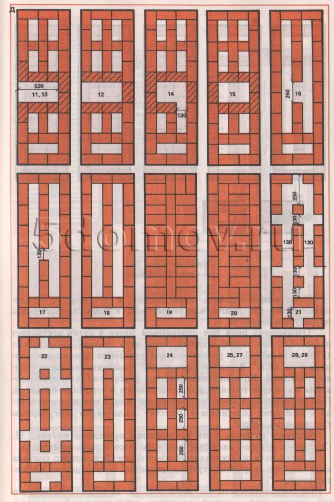
Fig. 9. Heating stove with bottom heating measuring 1880 × 640 mm d - masonry 11-28 rows
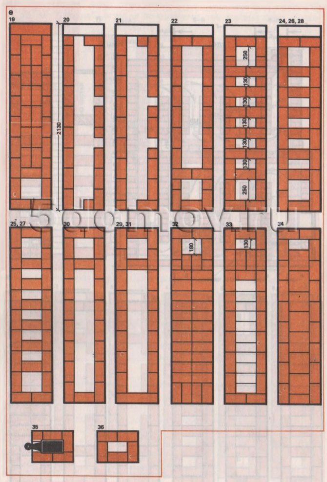
Fig. 9. Heating stove with bottom heating, size 1880 × 640 mm e - masonry 29-36 rows
The laying of the stove does not pose any particular difficulties, but first you need to study the drawings of the sections and the order of the brick laying well.
From the horizontal (along A-A Fig. 9, b) section it can be seen that there is a horizontal chimney under the ash pan. The firebox is lined with refractory bricks.
When laying the second row, you must strictly adhere to the order. The masonry of the fifth row determines the main dimensions of the chimneys of the lower heating chamber. The laying of the twenty-first row must also be carried out strictly in order, a chimney with a width of 130 mm is left at the vertical channel.The masonry of the twenty-fourth row also determines the main dimensions of the chimneys of the upper heating chamber. The rest of the rows of the oven masonry are similar to those of the previous ovens.
Improved Russian oven WITH TOP heating PR-3500V
Traditional Russian stove PR-3000, despite its positive qualities and extreme simplicity of the device, has disadvantages: a large coefficient of excess air; suction to the flue gases of cold air entering the firebox through the open furnace opening in the hailo, as a result of which the combustion process is ineffective; the need to warm up the entire massif of the stove, even in those cases when they are only preparing food, and there is no need for heating the house and baking bread.
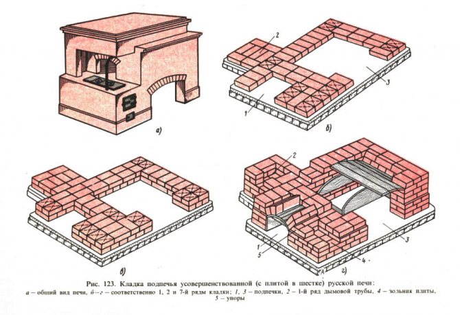
In addition, heat is accumulated by the arch and hearth massifs mainly due to radiation, and the flue gases come into contact with a poorly developed convective surface, which predetermines large heat losses with combustion products escaping into the atmosphere. To eliminate the noted disadvantages of the PR-3000 oven, folk craftsmen have developed an improved Russian PR-3500V oven, which includes a kitchen hearth (stove) in its design, which serves for cooking in warm periods of the year. The plate is placed, as a rule, in a pole (Fig. 123, a).
Consider the sequence of laying an improved Russian stove with dimensions in terms of 2000 x 1200 mm. The root pipe is adjacent to the left wall of the furnace.
First row. The base of the pipe 2 is laid out (Fig. 123.6), and also small 1 and large 3 subheats begin to form. Second row. Due to the fact indicated in fig. 123, in the method of placing bricks, a good dressing of the joints in all directions of the furnace being erected is achieved.
Third row. Lay, as the first, except for the place of formation of the ash pan 4 plates. In this place, bricks shortened by 50 mm are laid, forming a gap equal to 190 mm, and the laying is continued again, as shown in the figure of the 1st row. The depth of the ash pan is one and a half bricks, i.e. 380 mm, and the height is 65 mm. The first three rows of the root pipe are solid masonry.
Fourth row. The laying of the row begins with a ledge (cut), which is carried out similarly to that described in § 62. From the front of the furnace wall, stops 5 of the arch of a small sub-furnace 1 are formed. A 120 mm wide opening is left in the root pipe 2, intended for cleaning. On the right side of the Russian PR-3500V stove there is a large subheat 3. A heel for its arch is formed on the 6th row, and a heel for an arch with a thickness of 250 mm - on the 7th row. As can be seen from Fig. 123, d, the same formwork is used both for the vault and for the arch of a large sub-furnace.
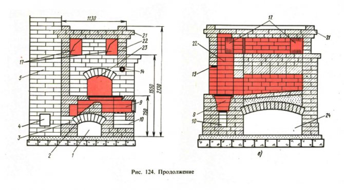
Elements of a cooker with a hob are shown in fig. 124, a. The stove, placed in the pole, consists of a small sub-furnace 1, covered by a vault 2, which transfers its thrust to the heel 3. In the main pipe 5 adjacent to the furnace, containing cleaning 4, a valve 6 is installed, to which the gas duct 7 fits. the path along the gas duct, go around the pass 8, limiting the firebox 9 from the end, and go into the main chimney 5. Since the plate of the Russian stove PR-3500V is designed for any type of solid fuel, it contains a grate 11 and an ash pan 10 located under the furnace door 12.
Fifth row. In order to block the ash pan 10, a full-size brick is laid above its opening, resting on its walls. The next row is placed in such a way that the seam in the masonry falls above the specified brick.
Sixth row. Mount the grate 11 In order for the grate to expand under the influence of temperature, a gap of about 5 mm is left between the grate and the walls.
Seventh row. The opening for the furnace door 12 begins to form in this row. To do this, put two three-quarters in front of the row. In addition, each of these bricks is cut lengthwise, chipping off 30 mm from them, which will provide the necessary dressing in the next 8th row. The width of the firebox 9 in the lower plane is 250 mm.
From the rear side the firebox is limited by pass 8, which is located on the arch 2. In fig.124, and two bricks are visible, indicated by the number 8, in which the pokes located in the direction of the gas duct 7 are hewn away. These bricks serve as the base of the pass, due to which the fiery torch from the firebox cannot get into the chimney 5. Three more rows containing two bricks are laid on the bricks lying at the base of the pass (Fig. 124.6).
The longitudinal section of the slab of the Russian stove (Fig. 124, c) shows the profile of the pass 8, according to which it can be determined that, in addition to the bricks facing the gate valve 6, the bricks of the upper row are also chipped, but already from the side of the firebox. Thus, the pass provides good aerodynamic characteristics of the gas path of the plate.
The cross section of the slab (see Fig. 124, c) shows that its 280 mm high firebox consists of four rows of bricks laid flat. To increase the furnace volume, the two middle rows (8th and 9th) are beveled. A cooking deck 13 is placed on the 10th row. The flue 7 starts from the 6th row of masonry. In fig. 124, a, b it can be seen that the rear side of the pass 8 is mated with the mouth of the gas duct 7. Behind the front side of the furnace, the left wall of the gas duct forms an angle with the front plane of the main pipe 5. In the direction from the middle of the corner, a cast-iron valve frame is placed on the edge 6. Section of the gas duct along the entire length, there should be at least 200 x 200 mm, therefore, the corners of the bricks that form the plane of the gas duct constrict. The bricks of the flue overlap (9th row), poured into the masonry, are also hewn, which makes it possible to keep its cross section unchanged.
Ninth row. This row ends with bricks placed over valve 6.
Tenth row. This row, overlapping the gas duct (Fig. 124, d), completes the laying of the slab, the cooking floor of which simultaneously serves as a pole. In the same row, the furnace door of the stove overlaps. For this, strip steel 50 mm wide and 4000 mm long is laid on the door frame, which serves as a support for the brickwork. The slab is stiffened by a corner steel frame that frames the 10th row masonry.
An additional improvement of the Russian stove is a developed convective system (Fig. 124, e), which is formed from gas ducts located above the crucible. As a result, the flue gases, before entering the chimney, make a path, during which they give additional heat to the furnace mass. The channels of the convective system 17 represent one horizontal smoke circulation adjacent to the main pipe 5. The cross-section of the supra-furnace gas duct is taken equal to 200 x 250 mm, that is, in height it is formed from three bricks laid flat one on top of the other. At the entrance to the convective system, a valve 18 is installed, located in a vertical plane (on an edge).
The functional diagram of the PR-3500V furnace differs from the scheme of a traditional Russian furnace in that the flue gases, having risen into the shield, are directed through the valve into the channels located above the crucible, heat them and then enter the chimney. The second element of the support is a steel strip 15 (see Fig. 124, d) 50 wide, 1150 long, 10 ... 15 mm thick. The strip is laid on the L-shaped tubular element of the pole support embedded in the masonry. At the same time, it is bent around the perimeter of the pipe. The upper end of the first support element is flattened, which allows it to be placed within the seam thickness between the 7th and 8th rows of masonry on the right side of the front wall 20 of the furnace. Above element 14, in the process of laying the walls 20, a slab 19 is left, consisting of two bricks fired by 120 mm, with which the bricks of the shield will subsequently be tied.
On the installed metal structures, a shield | approx 22 is laid out (Fig. 124, e), the wall thickness of which is 120 mm. Its front wall is erected on a steel strip 15, which is fixed to a pipe. Under the overlapped flap, the inlet and outlet of the convective system 17 of the supra-heating part are placed. the latch 18 is closed and the latch 16 is opened. In summer, both valves are closed. During cooking, hot gases escape from the stove, bypassing the mass of the stove. At the same time, the slide valve of the plate 6 is opened (Fig. 124, a).
The flue gases enter the convective system of the above-furnace part of the Russian PR-3500V stove through a flap that rests not on the arch, as provided in the traditional design, but on metal structures made in the form of a spatial support. One element of the stand - a metal rod 14 of the L-shaped form (see Fig. 124, d) is made of a pipe with a diameter of 25 or 32 mm. A pipe with a length of 1150 mm is bent at right angles in the cold state using a pipe bender or manually, heating it with a blowtorch or gas torch. When bending in a hot state, the radius of curvature is taken to be at least three pipe diameters, and the length of the heated section is 150 ... 180 mm.
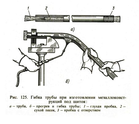
Before the flexible pipe (Fig. 125, a), fill it with well-dried sand 2, tapping its surface with a hammer. Then the open end is closed with a plug 3 with an opening for the escape of vapors generated during the heating process. Having marked the place of bending, the pipe is heated (Fig. 125.6) and, using a template, is bent at a given angle.
Consumption of materials
| Ceramic bricks, pcs | 1200 |
| Ordinary clay, m3 | 1,5 |
| Sand, kg | 1,2 |
| Steel strip 50 x 10 mm, m. | 6,1 |
| Corner 50 x 50 x 4 mm, m. | 3,4 |
| Pipe with a diameter of 25 mm, m | 1,2 |
| Grizzly grate 270 x 220 mm, pcs | 1 |
| Smoke dampers, pcs | 3 |
| Furnace doors, pcs | 1 |
| Cooking floor 710 × 400, pcs | 1 |
"Previous table of contents next"