Pros of the Valtec system
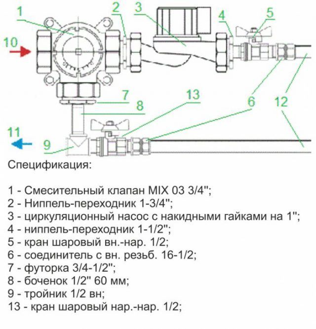
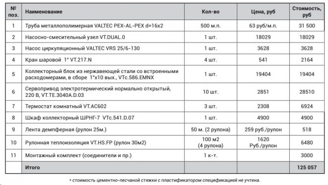
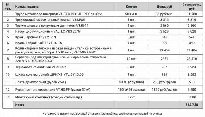
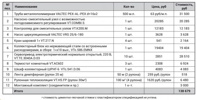
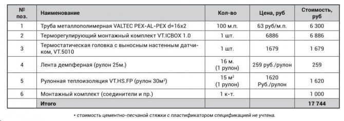
Valtec mixing unit specification for underfloor heating
Before starting installation and selecting a mixing unit for a Valtec underfloor heating, it is necessary to analyze the advantages of this type of water circuit.
- Thanks to high-quality materials, durable fasteners, reliable operation is ensured.
- Modularly designed components fit exactly together, eliminating the risk of leaks.
- The manufacturer has provided for the production of related materials required for thermal and waterproofing equipment.
Calculation instructions
In order to correctly develop a project for laying a warm floor, a preliminary calculation of the main indicators will be required, focusing on their average values.
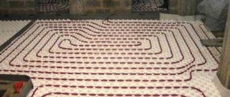
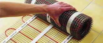
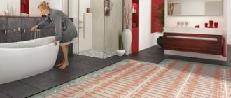
Do-it-yourself installation of a water-heated floor
Various factors have to be taken into account, including the role of the water floor as the main type of heating or its use as an additional source of heat. Since a detailed calculation for self-execution is a complex process, in practice, averaged parameters are used.

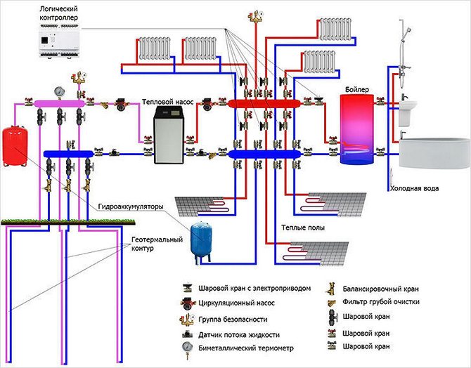
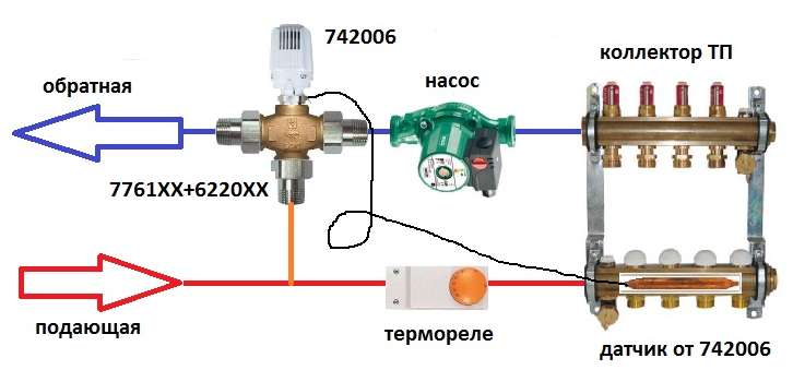
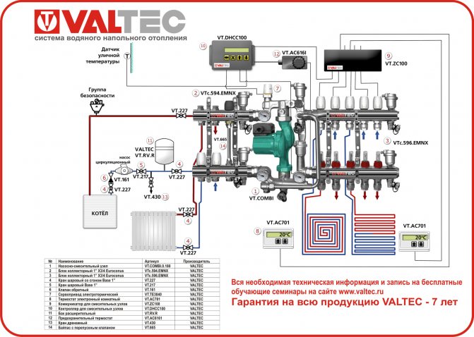
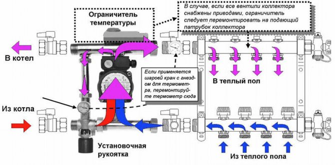
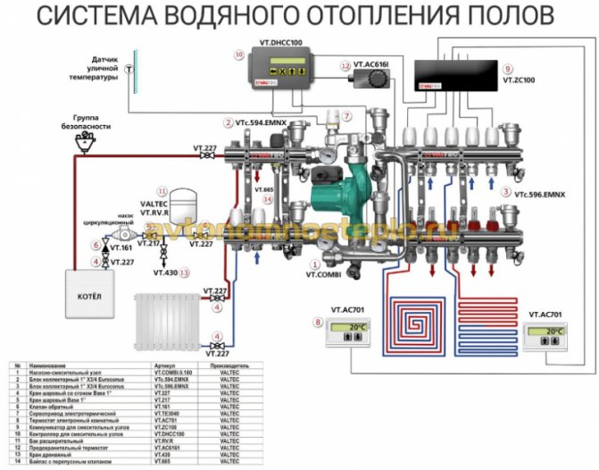
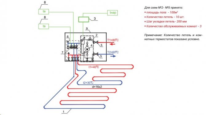
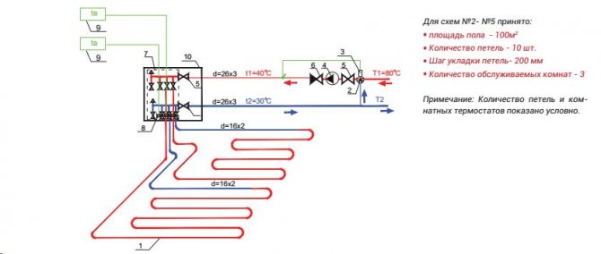
Valtec mixing set connection diagram
- The rated power has a range of 90 - 150 W / m2. Higher values are selected for rooms with high humidity levels.
- When calculating the laying step, it is necessary to focus on the range of 15–30 cm. With this indicator, the specific heating power is in inverse proportional relationship. That is, the larger the step, the less power.

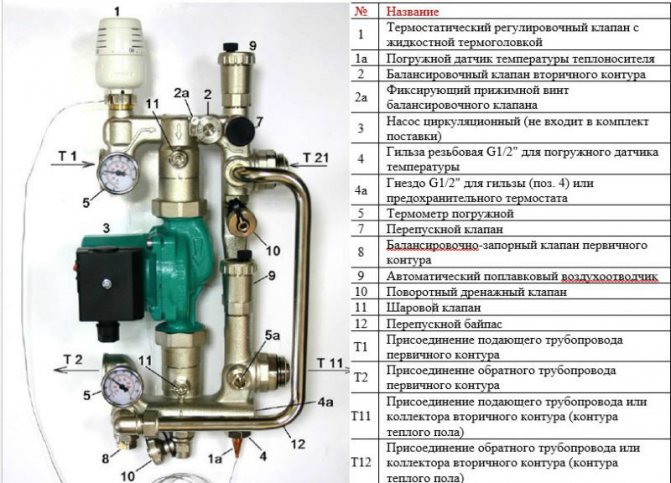
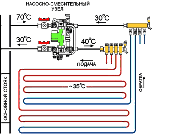
Thermal-mechanical diagram of the pump-mixing unit - Despite the fact that with a large diameter of pipes, a larger amount of coolant passes through them, the thickness of the screed serves as a limiter for this indicator, which is not recommended too large so as not to create excessive load on the floor. Therefore, Valtec pipes made of modern cross-linked polyethylene with an anti-diffusion coating, with a diameter of 16 to 20 mm, are taken into account, and Valtec press fittings act as connecting parts.
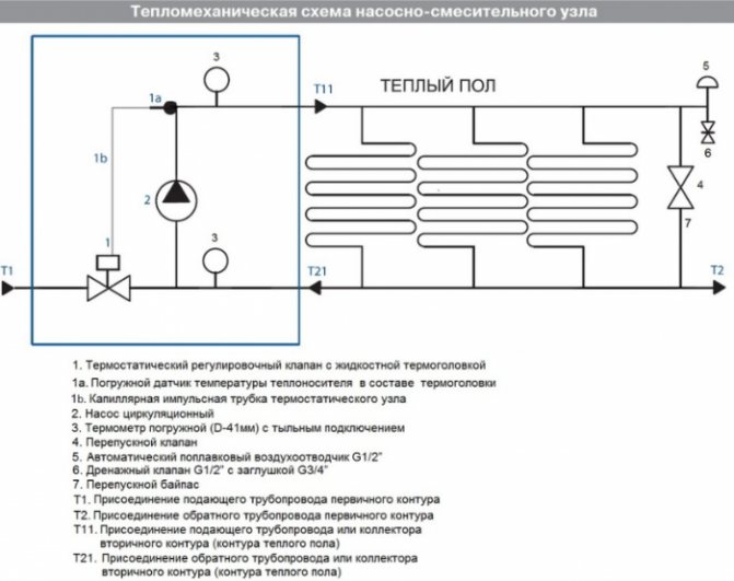
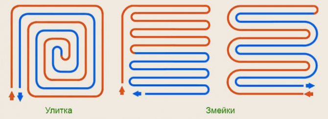
After determining the key parameters, a scheme can be developed on which the most rational pipe laying is determined on an exact scale. After that, their total length is calculated. At the same time, it is considering where the pumping and mixing unit and control elements will be located.
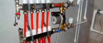
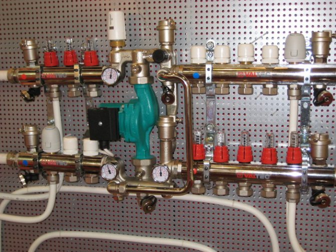
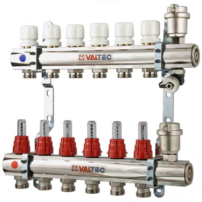
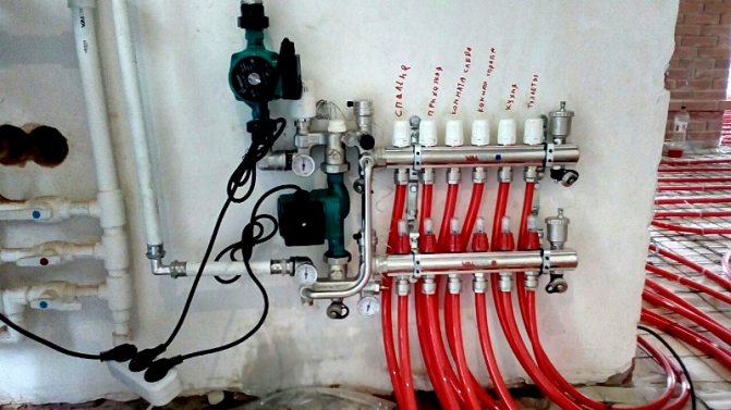
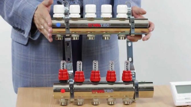
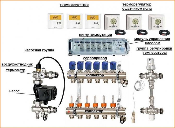
How to assemble a collector?
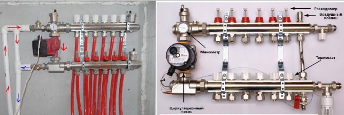
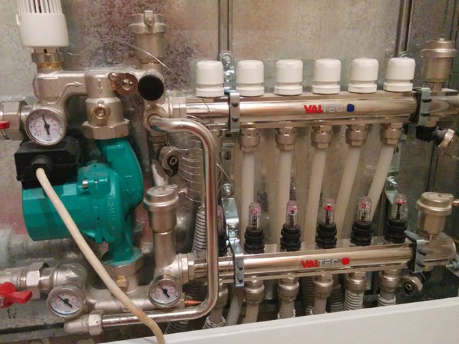
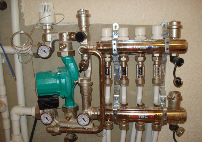
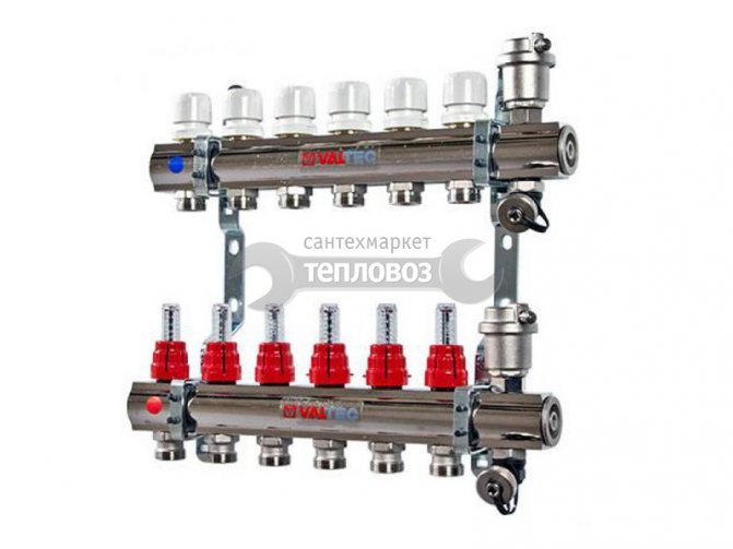
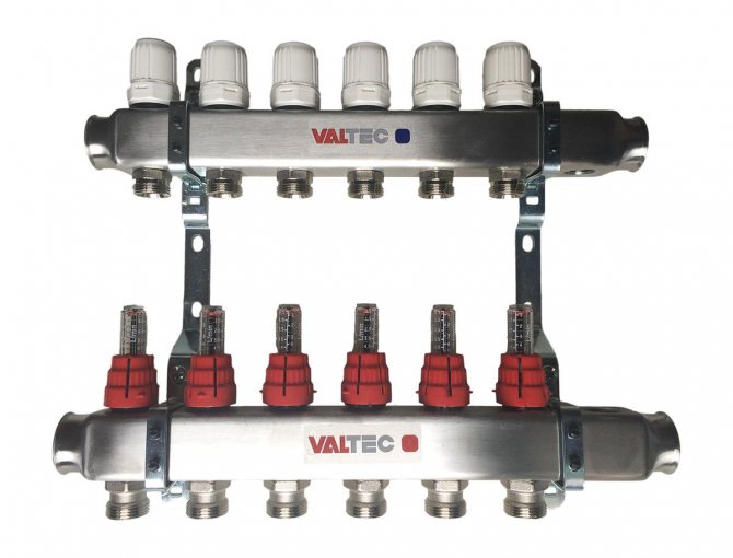
The Valtec distribution block is assembled. The hot pipe already has flow meters installed. There are thermal heads on the cold line, but the product may only have outputs for attaching temperature control devices. They are protected by plastic caps. The manufacturer makes it possible to choose which automation to install: a thermal head, a servo drive.
It is necessary to connect some small elements to the collector group:
- On the right, shut-off valves are connected to the tubes. The set includes 2 pcs.
- A float device is connected to the valves for air discharge.
- Drain valves are connected opposite the air vents on the lower side of the pipes.
- The ends of the comb are closed with plugs.
We recommend: How to choose a material for a warm water floor?
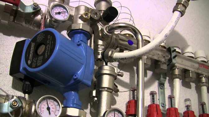
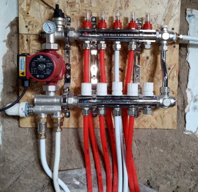
A circulation pump and a three-way or two-way valve are separately connected to the manifold. These devices are sold separately. They are connected to the left of the tube into which the cold coolant enters. Use brass threaded fittings.
Cold and hot circuits are removed from metal pipes that are connected to a boiler or stove. They are connected by means of a bypass at the outlet of the collector group. A circulation pump with a temperature sensor is installed between the circuits.
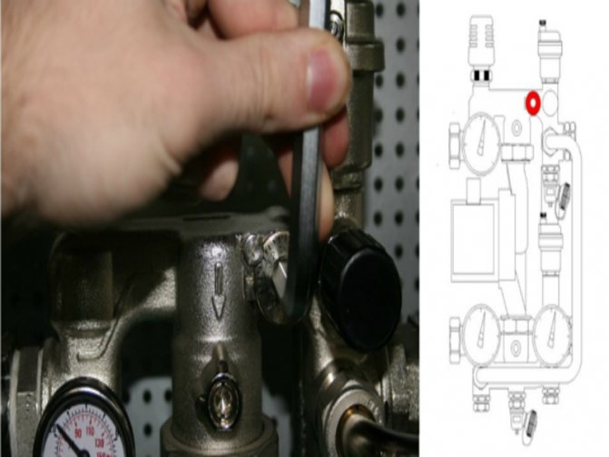
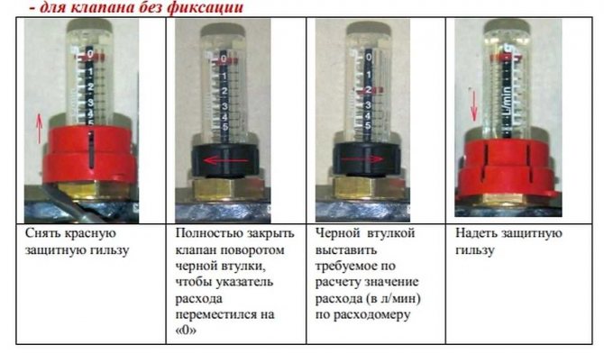
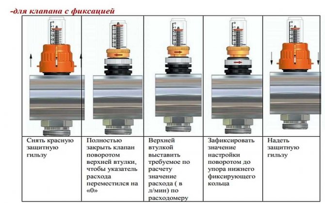
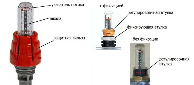
Adjustment of the rotameter is carried out when testing the heating system. The thermowell must be removed from the device. Using the red ring, the upper sleeve, set the rotameter to zero.
Then, using the same sleeve, the valve is installed on o for large rooms, on o for small rooms. To fix the parameters of the rotameter, the lower ring is turned to the right until it stops.
Return the protective cap to its original place. The variable area flowmeter may not have a retaining ring. In this case, the filling rate of the pipeline is set without fixing. Valve function should be checked regularly.
Collectors "Valtek" for underfloor heating are installed with a liquid heating system. The coolant can be water, antifreeze, glycol fillers, which do not freeze at low temperatures. If the heating system is not used, then the coolant does not need to be drained.
The number of circuits on the distribution block is 3-12 pcs. If necessary, additional equipment can be connected to them in order to increase the flow capacity of the coolant to all rooms in the house.
The comb is fixed on the wall or placed in a manifold cabinet. The manufacturer gives a 10-year warranty for the equipment. Service centers are located in St. Petersburg, Moscow. The unit will serve for over 50 years.
If necessary, the rotameter or thermal head can be replaced without shutting down the heating system. When using a programmable thermostat, the operation of the underfloor heating control unit can be carried out through electronic gadgets.
We recommend: How to choose a plasticizer for a warm floor?
YouTube responded with an error: Access Not Configured. YouTube Data API has not been used in project 268921522881 before or it is disabled. Enable it by visiting https://console.developers.google.com/apis/api/youtube.googleapis.com/overview?project=268921522881 then retry. If you enabled this API recently, wait a few minutes for the action to propagate to our systems and retry.
- Similar posts
- How does the floor heating automation work?
- How to put polystyrene foam for underfloor heating?
- How are PEX pipes for underfloor heating connected?
- How to assemble a collector for a warm floor?
- How to connect a mixing valve for underfloor heating?
- What are the characteristics of Aura underfloor heating?
Key features of the mixing unit
In order for the installed water circuit to function effectively, it is necessary to correctly calculate the entire system and correctly install the Valtec floor heating mixing unit in accordance with the provisions that are reflected in the instructions attached to the kit.
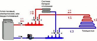
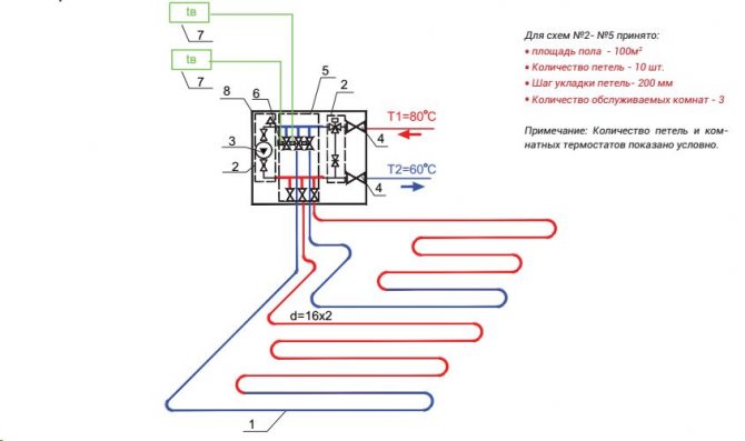
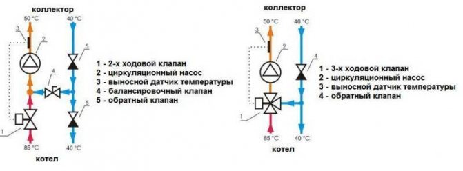
Connection diagram of the mixing unit to different types of heating
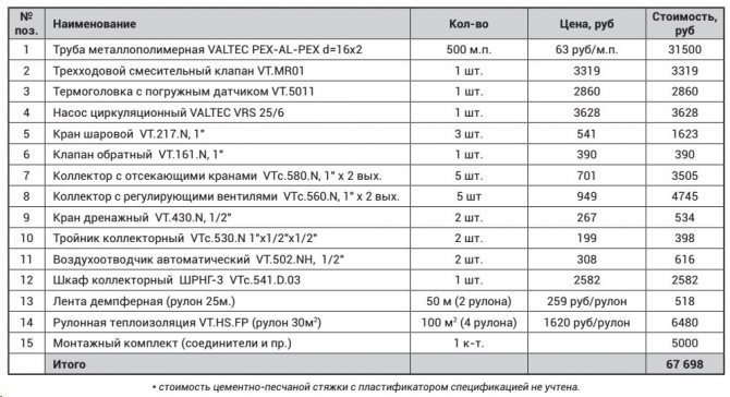
Pump-mixing unit parameters:
- the cross-section of pipes is ¾ ", collectors - 1";
- there are 12 branch pipes in the structure;
- the pumping system is 18 cm long;
- the temperature regime of heated water in the system is maintained up to 90 ° С;
- maximum pressure value - 10 bar;
- throughput - 2.75 m3 / h.
Valtec pump and mixing unit specification
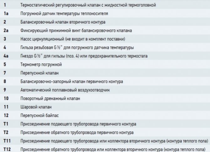
The pipes have an external thread with a Eurocone connection.
Pump and mixing unit for underfloor heating
Functionality
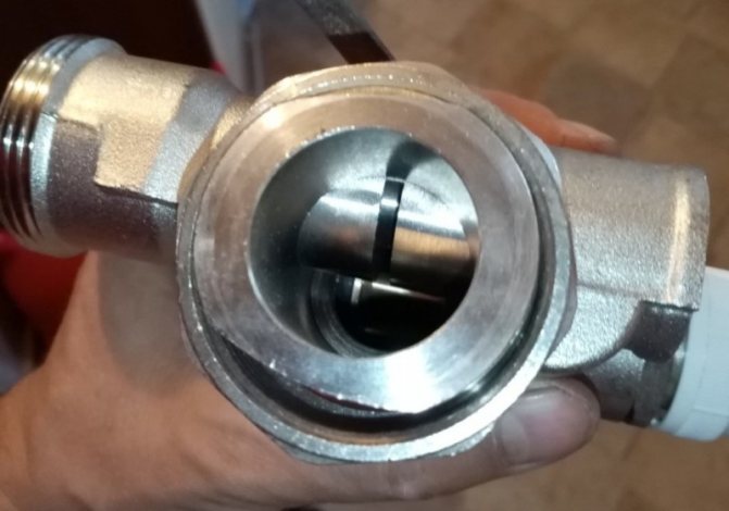
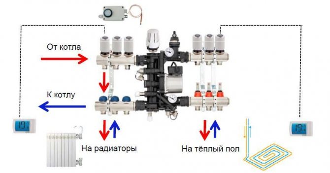
The main purpose of the pumping and mixing unit is to stabilize the temperature of the coolant when it enters the water circuit by using it to mix water from the return line. Thus, the optimal functioning of the underfloor heating occurs without overheating.
The following service elements are included in the Combi assembly:
- drain valves;
- air vents;
- thermometers.
How the Combi unit works
The following organs are used to adjust the knot:
It is permissible to connect an unlimited number of underfloor heating branches to the VALTEC COMBIMIX node with a total power of no more than 20 kW
- a balancing valve on the secondary circuit, which provides mixing in the required proportion of heat carriers from the supply and return pipelines to ensure the specified temperature;
- balancing and shut-off valve on the primary circuit, responsible for supplying the required amount of hot water to the unit. It allows you to completely shut off the flow if necessary;
- bypass valve to open an additional bypass to ensure pump operation when all control valves are closed.
The connection diagram is designed taking into account the possibility of connecting the required number of floor heating branches to the pumping and mixing unit with a total water consumption not exceeding 1.7 m3 / h. The calculation shows that a similar value of the coolant flow rate at a temperature difference of 5 ° C corresponds to a power of 10 kW.
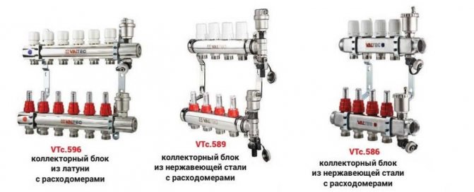
If several branches are connected to the mixing unit, it is advisable to select manifold blocks from the Valtec line with the designation VTc.594, as well as VTc.596.
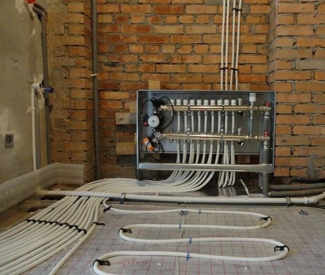
Manifold cabinet
One of the important points in the design of a water-heated floor system is to determine where the manifold cabinet will be located. To place it in the wall, you need to make a hole 60 cm by 40 cm, 12 cm deep. We install a cabinet in this niche, in which we will definitely place a Valtec mixing unit for underfloor heating. The mixing unit is the main element of the underfloor heating, in which hot water from the boiler and cold water from the reverse circulation system are mixed.
It regulates the temperature and flow of hot water, connects the circuits. All the necessary control and measuring devices are installed in this unit, with its help you can always maintain the set temperature and store the heat of your home. When we install the cabinet, we will be the first to fix the ends of those pipes that supply hot water and send water to the boiler for heating. A pipe for a warm floor must be made of reliable and environmentally friendly materials, for Valtec it can be multilayer, made of polyethylene, or metal-plastic (the standard size is 1.6 cm in diameter). These materials are characterized by durability and elasticity, they are quite durable, with a smooth surface. According to their characteristics, they are thermally conductive, do not corrode. Choosing a pipe for a warm floor is not an easy task. Now a sufficient number of manufacturers are engaged in this, but Valtek pipes have proven themselves positively. They will last a long time - about 50 years.
Installation Algorithm
After the preliminary calculation of all the components has been completed, the installation of the warm floor begins directly, involving the passage of several stages.
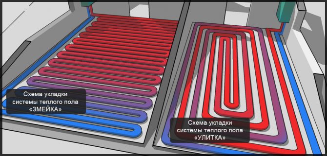
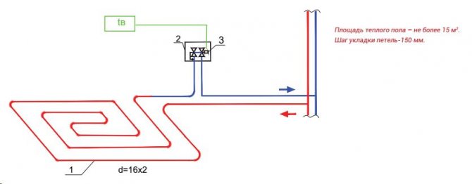
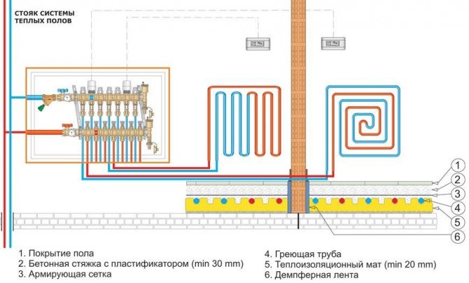
Floor heating scheme
- Installation at a pre-selected location of the manifold cabinet. It houses a module consisting of a manifold block and a pump-mixing unit with ball valves, through which the connection to the high-temperature circuit will be made.
- Preparation of the floor plane. If there are significant irregularities, measures are taken to eliminate them. The most effective option is a rough screed.
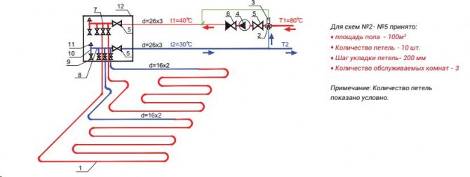
Connection diagram of the pumping and mixing unit to the warm floor - Fixation along the perimeter of the damper tape, which serves as an element that compensates for the possible expansion of the screed that occurs when it is heated. It is attached to the walls so that after finishing there is a surplus, which is cut off before installing the plinth.
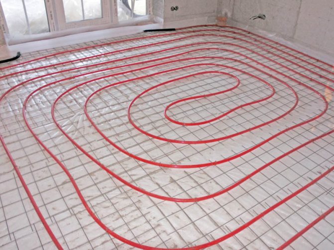
- Equipment for thermal insulation by laying on the leveled floor of expanded polystyrene plates with mounting bosses, under which waterproofing is laid, if necessary.
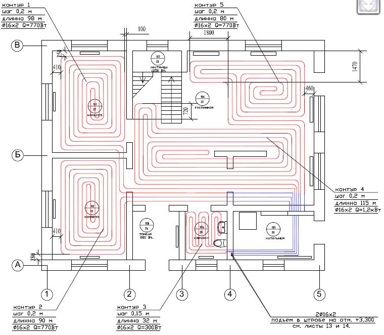
- A previously developed diagram serves as a guide for the subsequent layout of pipes.
Underfloor heating calculation
Before connecting a warm floor according to the developed scheme, it is necessary to make a preliminary calculation. You can do a rough calculation yourself in the following steps:
- Determine the location of the manifold. Most often it is mounted in the center of the floor.
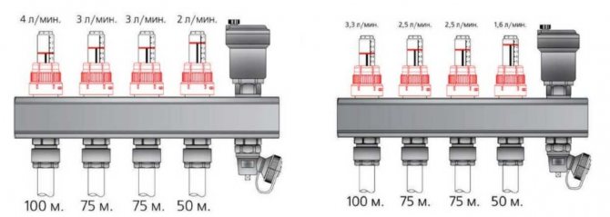
- Try to schematically depict the layout of the underfloor heating pipes, observing the following information: at a step of 15 cm, 6.5 meters of pipe are spent per square meter of pipe, the length of the pipe should not exceed 100 meters, the contours should all be approximately the same.
- We decide on the footage of all the contours and, in general, we can proceed with the installation.
Also, do not forget to make thermal calculations of the building. There are many ready-made calculators on the Internet. If the heat loss in the room does not exceed 100 W per square meter, then the warm floor will not require additional heating devices.
Customization
To connect the pipes to the manifolds, use a pipe cutter to cut to the desired length, a calibrator for chamfering and a compression fitting. It is difficult to carry out a detailed calculation at home, therefore, the instructions must be studied, which detail the setting of the pumping and mixing unit in a certain sequence.
- The thermal head is removed.
- For the balancing valve on the secondary side, the capacity is calculated using the formula.
Two variants of the mixing unit
kνb = kνt {[(t1 - t12) / (t11 - t12)] - 1},
where kνt - coefficient = 0.9 valve throughput;
t1 - water temperature of the primary circuit at the supply, ° С;
t11 - temperature of the secondary circuit at the coolant supply, ° С;
t12 - water temperature of the return pipeline, ° С.
The calculated kνb value must be set on the valve.
- Setting the desired mode of operation of the bypass valve at setting the maximum value of the differential pressure of 0.6 bar.
- In order for the underfloor heating to function efficiently, the required pump speed is adjusted. To do this, it is necessary to determine the value of the flow rate of the coolant in the secondary circuit system, as well as the pressure losses that appear in the circuits located after the unit.
Valtec mixing unit equipment
Consumption G2 (kg / s) is determined by the formula:
G2 = Q / [4187 • (t11 - t12)],
where Q is the total thermal power of the water circuit connected to the mixing unit, J / s;
4187 [J / (kg • ° С)] - heat capacity of water.
A special hydraulic calculation program is used to calculate the pressure loss. To determine the pump speed, which is set using the switch, according to the calculated indicators, a nomogram is used, which is in the instructions attached to the underfloor heating structure.
Connection diagram for underfloor heating circuits
- Operations are performed to adjust the balancing valve on the primary circuit.
- The temperature regulator is set to the temperature required for comfortable heating.
- A trial run of the system is in progress.
In the absence of leaks, it remains to perform a concrete screed, and after its complete hardening, lay the floor covering.
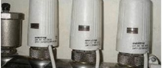
Varieties
There are the following types of mechanisms for adjusting the temperature of a warm water floor:
- Normally open. The valve is in the open state by default if there is no voltage. In this model, the coolant can freely pass through the valve;
- Normally closed. In this option, the valve is closed by default. In the absence of voltage, the coolant does not enter the system;
- Universal. These models can switch to one of the modes, where the valve will be in a closed or open state.

Normally open servo
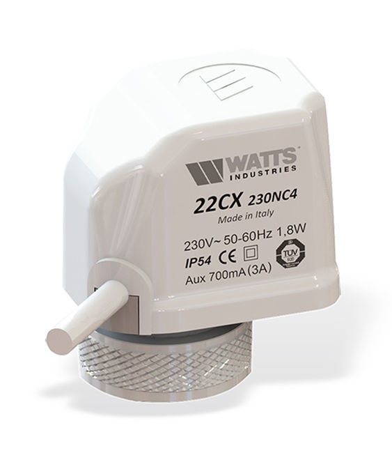
Servo drive Watts 22CX normally closed 220V

Universal