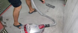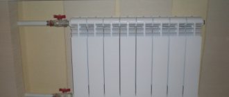
What is a water heat-insulated floor
Water underfloor heating is a low-temperature heating system, where the coolant is supplied with a temperature of 35-45 ° C, according to the norms not higher than 55 ° C. In addition, underfloor heating is a separate circulation circuit, which requires a separate circulation pump.
Underfloor heating has limitations on the temperature of the floor surface - 26-31oC. The maximum temperature difference between the distribution of the supply and return of a warm water floor is allowed no more than 10 ° C. The maximum flow rate of the coolant is 0.6 m / s.
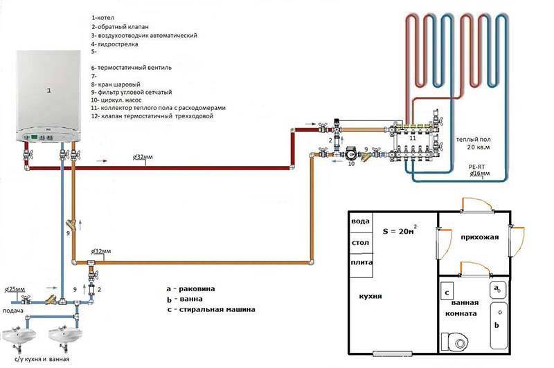
Scheme 1. Connection of underfloor heating directly from the boiler
This connection diagram for a water-heated floor has a heat generator, safety fittings with a pump. The heat carrier directly from the boiler enters the underfloor heating distribution manifold and then diverges in loops and reverses back to the boiler. The boiler must be set to the underfloor heating temperature.
In this case, two nuances arise:
- It is advisable to use a condensing boiler in the installation, because low temperature mode is optimal for him. In this mode, the condensing boiler has maximum efficiency. In a conventional boiler, when operating in low-temperature mode, the heat exchanger will fail very quickly. If the boiler is solid fuel, then a buffer tank is needed to correct the temperature, since this boiler is difficult to temperature control.
- A good option for underfloor heating is when it is connected to a heat pump.
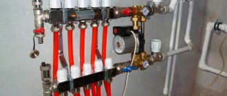
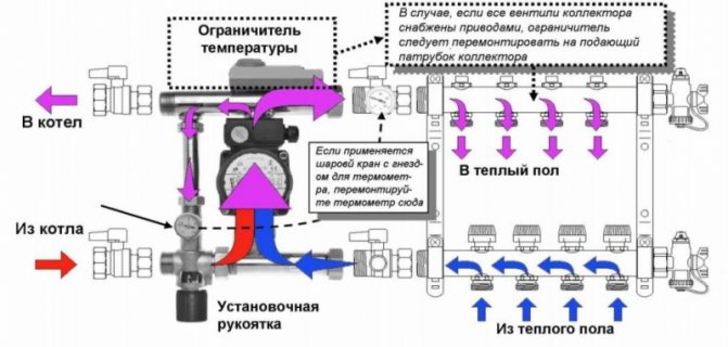
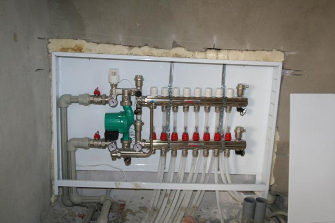
Mixing unit installation
mixing module
All mixing units have a balancing valve, with which you can meter the amount of cooled coolant when mixed with hot. This allows you to achieve a well-defined temperature of the coolant at the outlet from the unit, i.e. at the entrance to the underfloor heating loops. This significantly increases consumer comfort and the efficiency of the system as a whole.
Depending on the model of the unit, it may include other useful elements: a bypass with a bypass valve, a balancing valve in the primary boiler circuit, or ball valves on both sides of the circulation pump.
- sequential - fig. 2a;
- parallel - fig. 2b;
- combined.
In this case, the first two are considered the main ones, and the last scheme, respectively, represents their hybrid version.
The pump connected in series is operated only for the preparation of the heat carrier and its circulation in the underfloor heating circuits. A similar scheme, although it requires the use of two separate pumping units (for the primary and secondary circuits), however, is distinguished by better technological indicators than a parallel one.
The advantage of connecting the pump in parallel is that only one unit can be used to circulate the heating medium in the primary and secondary circuits. On the one hand, this simplifies assembly, and on the other hand, it requires the installation of more powerful pumping equipment. If the manufacture of a mixing unit for a small household system is done by hand, then by choosing a parallel layout, it is easier to avoid critical errors that can negatively affect the operation of a water heated floor.
Both in parallel and in series assemblies of NSUs, the use of thermostatic two-way (Fig. 2-5 and 7) or three-way (Fig. 1, 8 and 9) valves is practiced. Circuits with thermostats of the first type are recommended to be used for rooms with transformer substation areas of several tens of square meters.Therefore, they are quite suitable for the organization of underfloor heating in an average typical apartment. The mixing of the coolant in them is carried out after the two-way valve directly in the circulation flow of the underfloor heating system.
Three-way thermostats are themselves mixing devices. Inside their bodies there is a controlled admixture of the coolant from the primary circuit to the circulating flow from the TP system. Three-way thermostatic shut-off and control valves are recommended for installation in large heated areas, measured in hundreds of square meters.
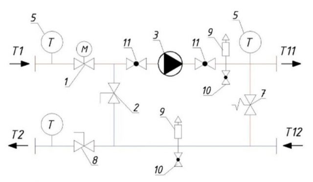
Figure 3
The assembly of water heating underfloor heating can be done entirely by hand. This applies not only to the installation of heating circuits or connection to the manifold distributor, but also to the assembly of the NSU. Understanding the principles of operation of its elements, as well as using typical working schemes, it is quite possible to assemble an operating efficient mixing plant.
If you follow the path of least resistance and spend a little more money, then you can turn to ready-made offers from well-known manufacturers of heating equipment. The assembly, installation and configuration of such NSOs is simple. And if everything is done in strict accordance with the factory instructions attached to them, then the result is guaranteed to be positive.
We suggest that you familiarize yourself with the Description and installation of a built-in hood in a kitchen cabinet
The Valtec pump-mixing unit has already been discussed above. However, some other ready-made NSO configurations have also proven themselves well among consumers. For example, equipment for the preparation of the heat carrier for the underfloor heating system from the German company Kermi (Fig. 8).
Figure 8
Kermi kit Standard ESM is equipped with a three-way valve (Oventrop), a circulation pump (Wilo Yonos PARA RS model) and a safety thermostat that controls its operation. The Oventrop valve module includes:
- distribution three-way valve;
- thermostat consisting of a drive head and an external attachment sensor;
- connecting circulation pipe:
- cap nuts (American), to which the supply and return pipelines of the primary heating circuit are connected, as well as devices on the side of the secondary circuit.
Kermi Standard ESM has the ability to adjust the maintenance of the heat carrier temperature in the range of 20-500C at a pressure in the TP system up to 6 bar. The adjustment is carried out automatically in accordance with the setting of the scale on the knob of the three-way valve.
Figure 9
Another assembly of the NSU Solomix from the Uni-Fitt company from a more budgetary series, but also well-proven in the Russian market. This is a ready-made mixing unit based on a three-way thermostat, with a built-in thermometer, heat pump, bypass and non-return valve and an automatic air vent.
In the NSU Solomix, manual temperature change is provided by means of an analogue thermostat adjustment in the range of 20-650C. The kit is designed to work in underfloor heating systems with a maximum pressure of up to 10 bar. And its form factor, which provides the bottom connection of the primary circuit pipelines, greatly facilitates the installation work.
In some cases, installation of a collector for a warm floor is not justified.
The main disadvantage of installing a system without a collector is the need to minimize the loss of the coolant temperature on the path "coolant heater - pipeline" and in the system itself. You also need to maintain the required temperature on the floor area. Therefore, it is recommended to consider the following requirements:
- Insulation of the walls of the room;
- Laying thermal insulation on the floor;
- Availability of high-quality window systems;
- Laying the floor in the immediate vicinity of the heating element;
- The area of the room is no more than 20-25 m2.
The main and common mistake when installing such a system without a collector assembly is an attempt to install it on too large an area.
However, some masters argue that in a situation where the "return" in any case will be cold, the installation of a condensate boiler can save. It has a high efficiency and such a device is not afraid of low temperatures for heating.
Is it possible to do without a mixing unit? Experts believe that the heating system can function normally without a mixing unit, provided that the heating in the house is organized using low-temperature circuits. This is possible if the water heats up only to a certain level.
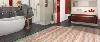
Features of laying warm water floors
Example: the heating is powered by an air source heat pump. If you use the same boiler for heating the house and heating water for the shower, then you cannot do without a mixing unit.
Water floor device
- The floor is laid in the immediate vicinity of the heating elements;
- The maximum area should not exceed 25 m²;
- It is necessary to contact a specialist who will help to calculate the power of the water floor and the cooling rate of the coolant in the water supply system. If the temperature difference is too high, condensation will form. High humidity on the surface of the pipes leads to rapid pipeline breakdown.
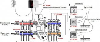
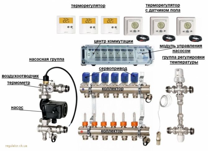
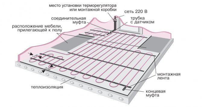
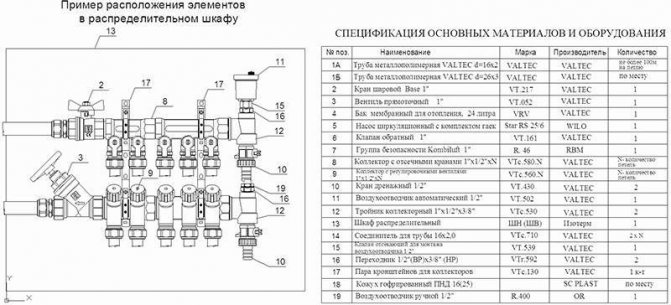
Diagram of structural elements and equipment of a water-heated floor
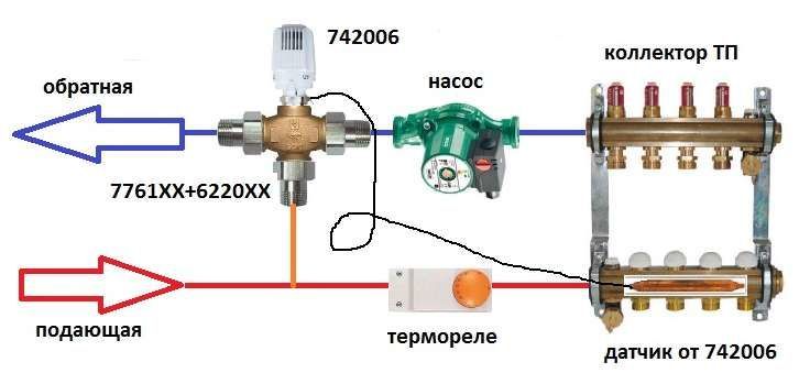
- On the reverse side of the collector, a TP thermostat is mounted, which in the future will be connected to a 220 V network. Such a connection allows you to slightly modify the direction of the coolant: first, the liquid flows from the boiler into the supply manifold, from where it is already heated and evenly distributed through the pipeline. The circulation of water through the pipes is produced by a pump motor;
- Having made a full circle, the water returns to the manifold. At this point, the manifold detects the temperature of the fluid and shuts down the pump motor. The movement of hot liquid gradually slows down, due to which the house is heated. The mechanism starts the pump motor again after the temperature drops, and the whole cycle repeats - first, the coolant enters the boiler, from where it is evenly distributed over the loops.
Experts believe that when the mixing unit for a warm floor was not installed with your own hands, it is better to play it safe by installing a relay. This device will allow you to completely cut down the functioning of the water floor if the temperature sensor detects too high a temperature of the pipes.
Wiring diagram for underfloor heating thermostat
Note that modern plastic can withstand high temperatures without any problems. For example, even the cheapest pipe can easily withstand 80–90 degrees. Please note that laminate and linoleum are not designed to overheat. 35-45 degrees is the maximum they can withstand.
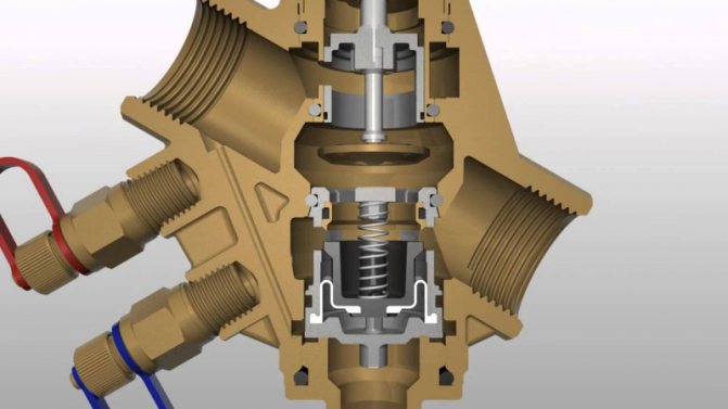
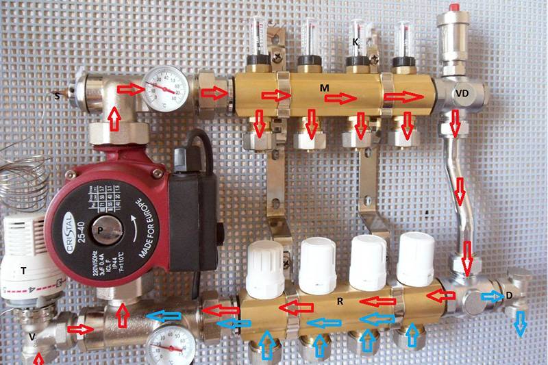
Mixing unit for underfloor heating on three-way valves
Hot water entering the collector of the underfloor heating system enters a special safety valve equipped with a thermostat. If the temperature for the circuit is too high, the valve opens to let in the cooled heat transfer medium for mixing.
The system manifold has two main functions. In addition to mixing water, providing it with an optimal temperature, it creates a circulation of the coolant. For this, a circulation pump is installed in the collector.
- The constant movement of water through the pipes creates an even heating of the entire floor surface. The collector can be equipped with additional elements:
- shut-off valves;
- drain valves;
- air vents;
If the circuit is created in one room of the house, the collector is equipped in this room. To install the box in the wall, a special niche is created.When creating underfloor heating in all rooms, it is possible to equip a manifold cabinet for several rooms. The collector can be located both at the inlet of the heating agent from the boiler, and at the return.
- The principle of operation of the mixing unit for underfloor heating is as follows:
- The heated coolant moves along the heating circuit and reaches the distribution manifold.
- Next, there is a safety valve and a temperature sensor that measures the current state of the coolant.
- If the temperature of the hot water is too high, the damper opens, supplying the required volume of cold water to the system, due to which the coolant is mixed.
- When the coolant reaches a certain temperature, the cold water supply stops.
- A mixing unit with a collector for underfloor heating not only regulates the degree of heating of the coolant, but also allows it to circulate through the system - and the following elements are used to implement these functions:
- Safety valve. This element provides the required amount of hot water. Its volume varies depending on the required temperature regime of the system.
- Circulation pump. A key element of the system that makes it possible for the coolant to move along each heating circuit, thereby ensuring an even distribution of heat in all parts of the heating system.
- Additional elements. Heating can be equipped with additional parts - bypass, air vents, valves and gates. The need for these elements is determined individually, depending on the features of the mixing unit.
Scheme 2. Installation of underfloor heating from a three-way valve
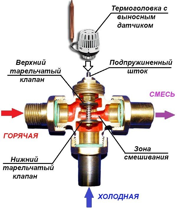
3-way thermostatic valve circuit
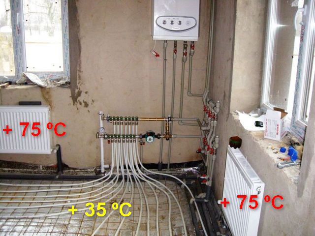
In most cases, with such a scheme of installation and connection of a water heated floor, we have a combined heating system, there are heating radiators with a temperature of 70-80 ° C and a floor heating circuit with a temperature of 40 ° C. The question is how to make forty out of these eighty.
For this, a three-way thermostatic valve is used. The valve is installed on the supply, after which a circulation pump is necessarily installed. From the underfloor heating return, the cooled coolant is mixed with the coolant, which is obtained from the boiler circuit and which is subsequently lowered to the operating temperature with the help of a three-way valve.
The disadvantage of such a wiring diagram for a warm floor is the impossibility of metering the proportionality of the mixture of the cooled coolant to the hot one, and a subcooled or overheated coolant can enter the warm floor. This reduces the comfort and efficiency of the system.
The advantage of this scheme is the ease of installation and low cost of equipment.
This scheme is more suitable for heating small areas and where there are no high customer requirements for comfort and efficiency, where there is a desire to save money.
In real life, the circuit is extremely rare due to the instability of the operation of the radiators connected to a single pipe. When the three-way valve is opened slightly, the heating circuit is fed, and the pump pressure is transferred to the main line.
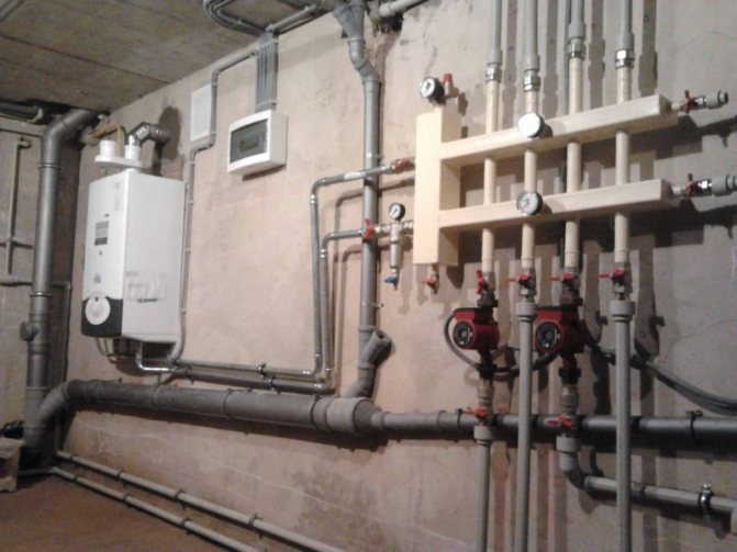
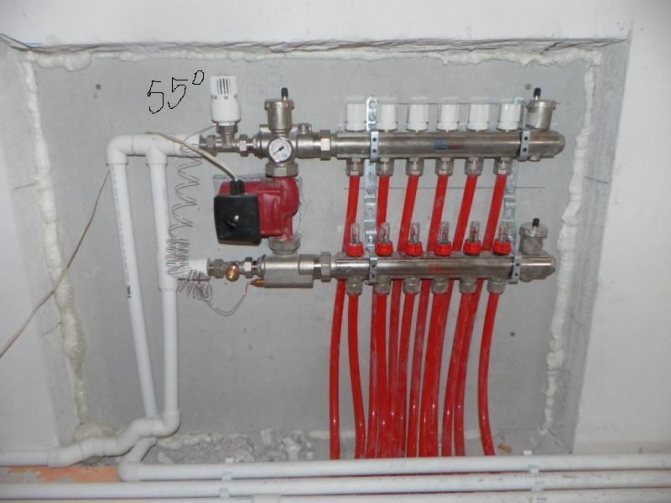
Implementation example:
Do-it-yourself mixing unit for underfloor heating: purpose and device
If someone tells you that the underfloor heating mixing unit is just a distribution manifold that divides the coolant flows into groups (so to speak, supplies it to various sections of the warm floor), you can safely blame it for incompetence in this matter.
In fact, what they are talking about (a distribution manifold or a manifold) is just part of the mixing unit, which also includes a lot of various equipment that serves not only to control the operation of the underfloor heating, but also to optimize this very work.
In general, this system is complex, and its structure should be dealt with in more detail - which is what we will do next. And let's start with the very collector, which most novice plumbers confuse with the underfloor heating mixing unit.
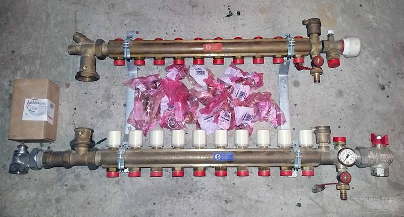
A collector or a distributor comb - without it, the very existence of a pumping and mixing unit for a warm floor can be questioned. It is this element of the assembly that is fully responsible for the uniform distribution of the coolant over all individual parts of the system.
There are two such collectors installed in the mixing unit - one is supply and the second collector, so the name “distributor comb” is in some way not entirely correct.
The distribution one is the one that is installed on the supply of the heat carrier to the warm floor, and the collecting one is the one that is mounted on the return pipeline.
Externally and structurally, they are similar to each other and represent a tube of large diameter, on the side of which there are threaded branches.
To make it clearer, I will say this - twisted together five, six or more tees of the same type and one diameter. Here is the first outline for solving the question of how to make a mixing unit for the underfloor heating circuit?
A hydrostatic gun, which, in fact, is the most real mixer for a warm floor - it is she who mixes the fresh coolant with the already "spent", restores its temperature to its original value and sends it back to the distribution manifold, which, in turn, supplies it to each separate branch of the water-heated floor.
A hydraulic arrow is installed at the very beginning of the mixing unit - it is a branch pipe connecting the supply and return of the heating system.
Exactly the same arrow is mounted after the boilers, in front of the distribution manifolds in the furnace - of course, the difference between them lies in the size and the ability to drive one or another volume of coolant through itself. Its purpose is to debug the process of mixing the coolant in the hydraulic gun - it is installed at the bottom of the branch pipe connecting the supply and return. At the same time, it acts as a tee.
It is for this reason that, if we talk about a factory hydraulic gun for a warm floor, then it is made already complete with a three-way valve. By changing the position of this tap, they achieve efficient operation of the underfloor heating, and in particular the effective reuse of the "spent" coolant.
Pump. You also cannot do without it - it is he who makes the coolant move quickly through all pipelines and effectively warm them up.
It is mounted on the return pipeline, between the hydraulic arrow and the collecting manifold. By analogy with it, a thermostat is installed on the feed, between the hydraulic arrow and the distribution comb - it is necessary only in the case of an automatic mixing unit. If we talk about the manual control option, then it can be completely abandoned.
Shut-off valves - installation of the underfloor heating mixing unit involves the use of two types of shut-off valves - these are ordinary ball valves, which are mounted before the mixing unit (their task is to cut off the entire unit from the heating system) and control valves, through which the system is debugged.
Air vents - usually installed at the end of the manifolds. In the manual version, they can be replaced with conventional ball valves or Mayevsky valves.
This is how the floor heating mixing unit diagram looks from the side - at least its professional version.
If we talk about making such a unit with our own hands, then, of course, it can be simplified to the maximum.We will talk further about how a homemade mixing unit for a warm floor works and works.
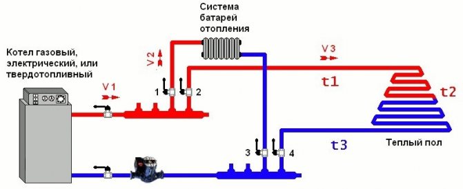
Scheme 3. Wiring of underfloor heating from the pumping and mixing unit
mixing module
This is a mixed connection scheme for a water heated floor, where there is a radiator heating zone, a warm floor and a pump and mixing unit is used. The cooled coolant is mixed from the return line of the heated floor to the boiler.
All mixing units have a balancing valve, with which you can meter the amount of cooled coolant when mixed with hot. This allows you to achieve a well-defined temperature of the coolant at the outlet from the unit, i.e. at the entrance to the underfloor heating loops. This significantly increases consumer comfort and the efficiency of the system as a whole.
Depending on the model of the unit, it may include other useful elements: a bypass with a bypass valve, a balancing valve in the primary boiler circuit, or ball valves on both sides of the circulation pump.
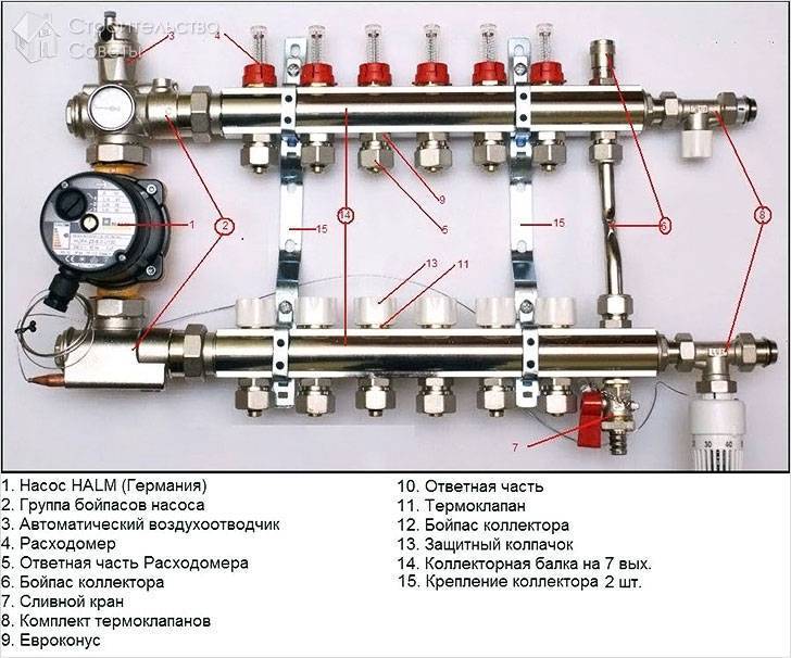
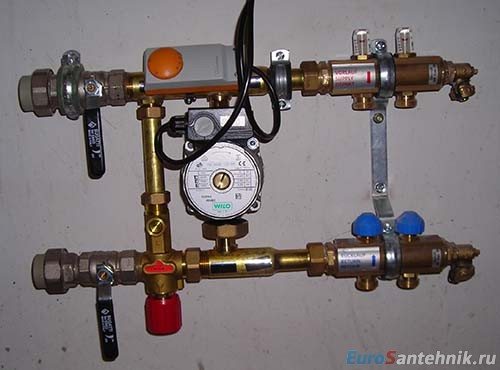
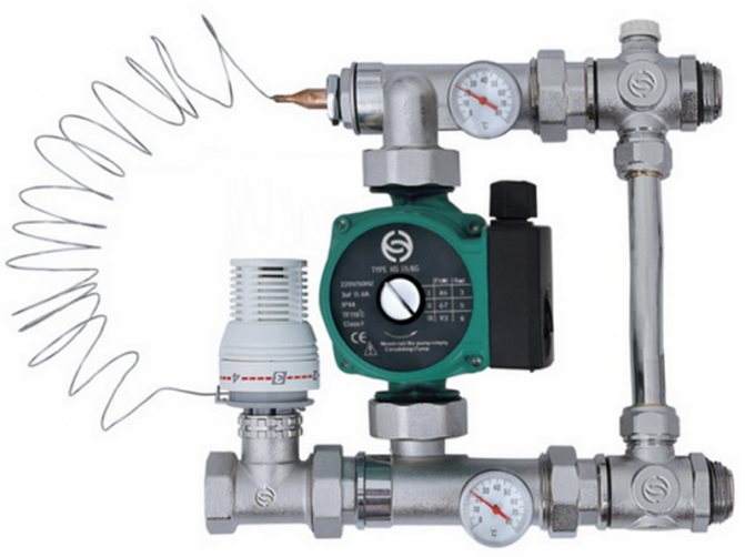
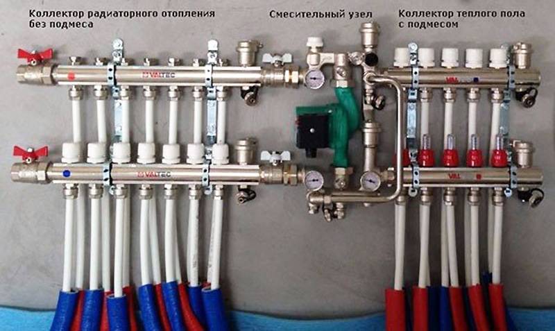
Component parts
The pump-mixing unit for a heat-insulated floor consists of several parts that allow, if necessary, to mix in cold liquid into the heating system.
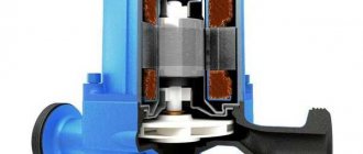
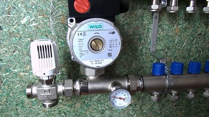
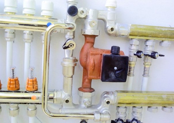
Circulation pump
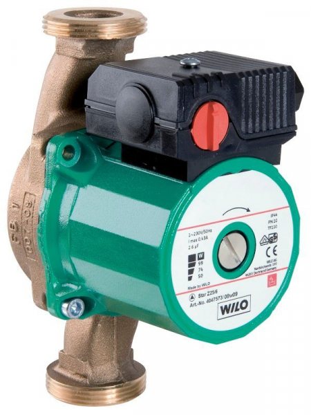
Circulation pump
It is designed to create pressure in the system and move the coolant in the pipes. Also, with the help of a pump, forced mixing of cold and hot heat carriers in the collector is performed.
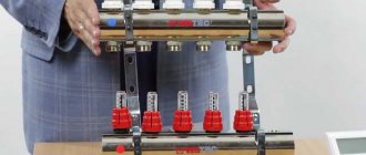
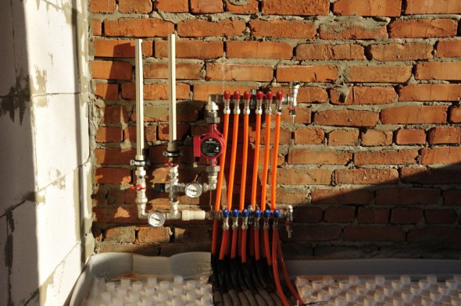
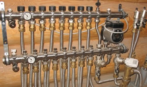
Collector block
The main part of the manifold system, including taps assembled in one block for all the necessary devices. Each block is designed for a certain number of heating circuits - from 2 or more.
In a plumbing store, you can purchase a ready-to-install device or make it yourself. For this, a piece of water pipe is taken, which is muffled on one side. Next, several bends are welded onto the pipe - two for each heating circuit.
The principle of operation of the circulation pump
But, as practice shows, it is much easier to purchase a collector block in a store than to try to make it yourself.
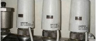
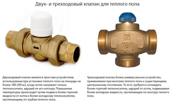
Thermostat
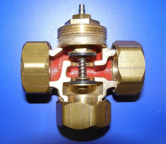
The thermostat has a two- or three-way valve
Related article: Several ways to make volumetric paintings from putty on the wall
The thermostat serves to supply hot water to the collector when the temperature in the heating elements drops below the set limit. The thermostat valve can be 2-way or 3-way.
The 2-way valve provides fluid from the return circuit to the floor heating circuit, and, if necessary, raises the operating temperature of the coolant and adds hot water from the supply circuit to it. Such a valve has a small throughput, therefore, the change in the temperature of the water in the pipes of the water floor occurs gradually.
The 3-way valve combines simultaneously with a mixer and bypass functions. Therefore, it is not necessary to use an additional pressure balancing valve when installing it. Often, such a valve has servo drives for controlling thermostats and controllers. Also, the 3-way valve can work in conjunction with weather-dependent sensors - in the event of a cold snap, the valve automatically increases the water supply to the supply circuit. For information on how you can adjust the heating temperature without a mixer, see this video:
In a private house, it is advisable to use a 2-way valve. It is able to ensure the normal operation of the mixer manifold circuit for a home with a total area of up to 200 sq. m. At the same time, its cost is significantly lower than that of a 3-way valve.
Balancing valve
Balancing valve device
The balancing valve is designed to dump excess coolant from the supply circuit to the reverse in case of excess pressure in the underfloor heating mix manifold.
In addition to the listed details, the floor heating mixing unit diagram may include filters, a thermometer, a pressure gauge, air relief valves and other additional monitoring and control devices.
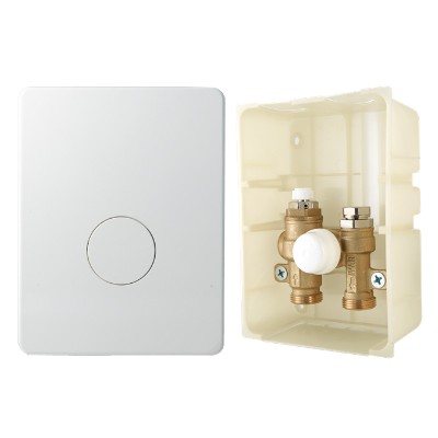
Scheme 4. Connecting underfloor heating from a radiator
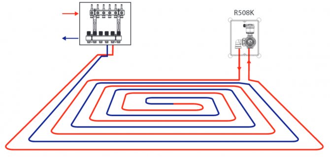
These are special kits designed to connect one underfloor heating loop for an area of 15-20 sq.m. They look like a plastic box, inside which, depending on the manufacturer and configuration, there may be temperature limiters for the coolant, room temperature limiters and an air vent.
The heat carrier enters the loop of the connected water underfloor heating directly from the high-temperature circuit, i.e. with a temperature of 70-80 ° C, it cools down in the loop to a predetermined value and a new batch of hot coolant enters. An additional pump is not required here, the boiler must handle it.
The disadvantage is low comfort. Overheating zones will be present.
The advantage of this connection diagram for a water-heated floor is easy installation. Similar kits are used when there is a small heated floor area, a small room with an infrequent stay of residents. Not recommended for use in bedrooms. Suitable for heating bathrooms, corridors, loggias, etc.
Let's summarize and summarize in a table:
| Connection type | Comfort | Efficiency | Installation and setup | Reliability | Price |
| Conventional gas, TT or diesel | ± | ± | + | ± | + |
| Condensing boiler or heat pump | + | + | + | ± | — |
| Three-way thermostatic valve | ± | ± | + | + | ± |
| Pump-mixing unit | + | + | ± | + | — |
| Thermal assembly kit | — | ± | + | + | + |
Plumbers and experts in heat and gas supply recommend avoiding schemes for connecting a water heated floor to working heating branches. It is better to supply the heating circuits of the underfloor heating directly to the boiler so that the underfloor heating can function independently of the batteries, especially in summer.
Homemade mixing unit for underfloor heating: design and assembly
Let's start by deciding on the materials that will be needed to make a homemade mixing unit for a warm floor. All of them can be bought separately in any construction market or in a store, or you can find an equivalent replacement for them, which will be much cheaper and, most importantly, will not affect the performance of the unit as a whole. Consider such a replacement and manufacture of a mixing unit, or rather its parts, in more detail.
Collector. It can be made in two ways - twisted from ¾ ”tees or soldered from polypropylene tees of the same diameter.
In the latter case, it will cost more, since each of the branches of the comb will have to be equipped with such a part as the MRN, the cost of which is not so small. In any case, high-quality tees are more suitable material - the main thing is to choose them correctly. In a situation with the manufacture of a comb, tees with two outer and one inner ends are suitable.
They are twisted together with the help of tow, without any additional fittings. How does the mixing unit for a warm floor work? It can be made even without a three-way valve. It is quite possible to do with the usual regulating, which is installed on the heating batteries.
In addition to him, you will need two tees exactly the same as were used to make the combs, as well as a pair of connecting nipples with an external and internal thread 50 mm long. Everything is assembled on tow - first, nipples (nipples) are screwed on both sides of the tap, and then one tee is screwed to the nipples on each side. Unfortunately, you won't be able to make it yourself - you will have to purchase it in the store.
It is mounted at the bottom of the hydraulic arrow using detachable connections (American ones, which, as a rule, come with the pump).Alternatively, the pump can be installed instead of the hydraulic arrow - you will get an excellent substitute for it that works just as well. At the same time, you will save on material. The contour of the warm floor: the mixing unit photo We connect the hydraulic arrow with the combs.
It is also better to use detachable connections here. If the pump will be installed as a separate element (not instead of a hydraulic arrow), then you will need to purchase a branch pipe, the length of which is equal to the length of the pump - it is installed on the supply, and the collector is screwed to the branch pipe. So the option with a pump instead of a hydraulic arrow turns out to be more economical in all respects.
And then we equip the combs with regulating taps, air venting machines or, again, Mayevsky's taps and, as they say, the end is - all that remains is to mount the mixing unit assembly for the underfloor heating in the right place in a special cabinet and connect it to the heating system ...
Here everything is already simple - feed to feed, return to return. Naturally, the unit is connected via shut-off valves.
In the same way, the warm floor is connected to the mixing unit - one end of it to the upper comb, and the other to the lower comb. In order not to get confused later, you need to observe the layout - the return flow and supply of one segment of the heated floor must be connected under each other. You will also need to supply power to the pump.
Basically, that's it. As you can see, assembling a mixing unit for a warm floor with your own hands is not very difficult.
The main thing is to understand the principle of its operation, to study the device, and everything else, as they say, is a matter of technology.
Do you think otherwise? Then purchase a ready-made underfloor heating mixer assembly and spend additional funds on its purchase. Alternatively, you can contact your friends who are competent in this matter.
Well, now it's time to finish the article. All the material that I wanted to share is reviewed. I hope it will be useful to you, and you will use it if you need to lay the mixing unit for underfloor heating with your own hands Improve your own practical skills and gain all the new knowledge, as they say: "It's never too late to learn!" That's all, thanks for your attention, successful and easy repair!
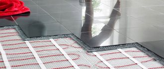
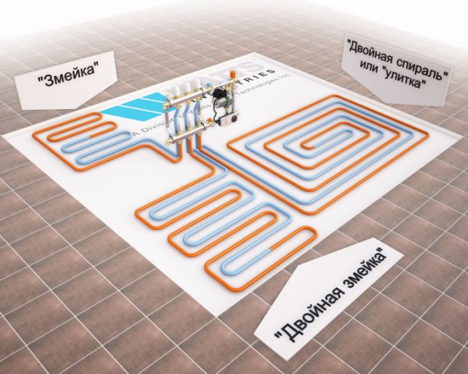
Laying schemes for a water-heated floor
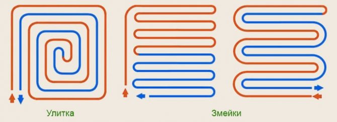
Ways to lay out pipes for underfloor heating
There are three main ways of laying a water-heated floor: snake, spiral (snail) and a combination of these options. Most often, a warm floor is mounted with a snail, in some places a snake is used.
Installation scheme "Snail"
Laying the warm snail allows the heat to be more evenly distributed throughout the room. With this wiring, the pipe is mounted in a circle to the center, then from in a circle in the opposite direction.
When laying out a warm floor with a snail, you need to lay an indent for laying the pipe in the opposite direction.
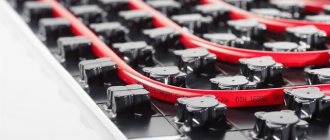
Laying underfloor heating with a snake
With this installation, the underfloor heating pipe is mounted in one direction and at the end of the circuit layout it simply returns to the collector return. With such a device, at the beginning of the circuit, the temperature of the coolant is hotter, at the end it is colder. Therefore, the snake layout is rarely used.
Application features
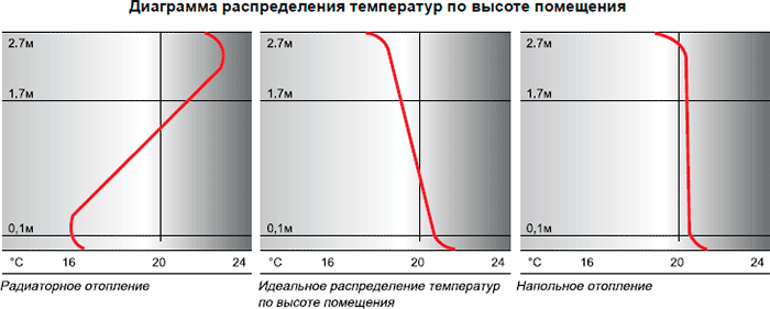
Underfloor heating first of all heats the lower surface and the person
Warm floors, unlike wall radiators, belong to low-temperature heating systems. If the recommended temperature regime of 30 - 35 ° C is exceeded, people in the room will experience obvious discomfort. It's all about the difference in room heating schemes when using these two heating methods.
Wall-mounted radiators primarily heat the upper half of the room. Therefore, in this case, the temperature at the floor may differ several times from the air temperature at the ceiling.
Ways of laying pipes for underfloor heating
The heating scheme of the room when using underfloor heating is completely opposite - the zone of greatest heating in this case is located in the lower part of the room, where people are usually located. Therefore, exceeding the recommended temperature of the coolant leads to tangible discomfort for the inhabitants of the house.
Related article: How to lubricate the door so that it does not creak
In addition, the increased temperature of the heating circuit can deform or peel the finished floor covering. To avoid this, the underfloor heating mixing unit is intended. A warm floor without a mixing unit will be completely impossible to adjust.
When setting the maximum temperature on the thermostat, take into account the nature of the floor covering. If the floors in the room are covered with laminate, parquet or carpets, this can significantly reduce heat dissipation. In this case, the maximum temperature threshold will need to be raised to 40 - 55 ºС.
Underfloor heating calculation
Before connecting a warm floor according to the developed scheme, it is necessary to make a preliminary calculation. You can do a rough calculation yourself in the following steps:
- Determine the location of the manifold. Most often it is mounted in the center of the floor.
- Try to schematically depict the layout of the underfloor heating pipes, observing the following information: at a step of 15 cm, 6.5 meters of pipe are spent per square meter of pipe, the length of the pipe should not exceed 100 meters, the contours should all be approximately the same.
- We decide on the footage of all the contours and, in general, we can proceed with the installation.
Also, do not forget to make thermal calculations of the building. There are many ready-made calculators on the Internet. If the heat loss in the room does not exceed 100 W per square meter, then the warm floor will not require additional heating devices.


How to choose the right 3-way valve
The key parameter of any three-way valve is throughput, i.e. the volume of water that the device is capable of passing through itself per unit of time. When choosing a device, this parameter should be correlated with the boiler performance.
One more nuance should be taken into account here. Even if the diameter of the inlets and outlets of the valve seems to be suitable in size, this in no way indicates the actual capacity of the device. This parameter is completely and completely determined by the internal section of the holes, which, depending on the design, are closed by a ball lock or a regulating head.
In some models, the dimensions of this hole can be 4 times less than the inlet diameter. In order not to be mistaken and not to be faced with the need to rework an expensive unit, you should carefully study the accompanying documentation before buying.
Another important parameter of the device is the cross section. Ideally, the valve should fit exactly the dimensions of the pipes of the heating system. If an exact match cannot be achieved, you will have to buy adapters.
In addition, you should pay attention to the following nuances:
- It is imperative to check the availability of accompanying documentation: warranty coupons, instructions for installation and operation, certificates and licenses.
- When choosing a material, you should give preference to brass or bronze. It is these metals that are best combined with hot liquids, and also have a low level of thermal expansion. You can distinguish products made of non-ferrous metals by weight - they are much heavier than cheap “stamping” made of pressed powder materials that do not have the required level of strength.
As for specific models, on the market you can find products from several companies that have long established themselves as reliable manufacturers:
- Esbe... A Swedish company whose products are distinguished by reliability, good performance and attractive appearance. The warranty period is at least 5 years.
- Valtec... A Russian-Italian joint venture producing thermo-mixing valves that combine affordable cost and good technical characteristics. The whole range of devices is guaranteed for 7 years.
- Honeywell... An American manufacturer, who has placed at the forefront the ease of installation of manufactured products. Three-way valves of this brand have a striking design, high reliability, but no less high cost.
We recommend that you familiarize yourself with: Features of a three-way valve equipped with an electric actuator
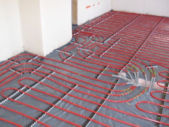
Underfloor heating installation
As you decide on the layout and connection of the water floor, you need to start the installation.
- Prepare the base of the warm floor. It should be flat with a minimum height difference.
- Install waterproofing as required by local regulations
- Lay 10 cm polystyrene on the first floor and 5 cm on the following.
- Lay polyethylene so that less screed comes into contact with the insulation
- If your fastening method is a reinforcing mesh, then lay it on polyethylene
- Lay out the underfloor heating pipe according to the approved scheme
- Pressurize the system
- Fill the screed