About the installation of additional units
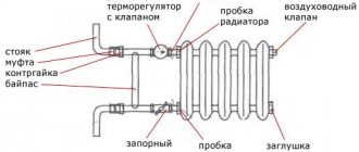
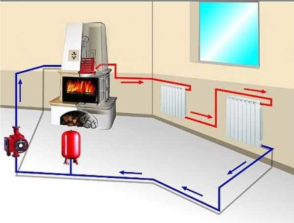
As a rule, in a closed or open radiator heating system, where the heat source is a single boiler, it is enough to install one circulation pump. In more complex schemes, additional units are used for pumping water (there may be 2 or more). They are put in such cases:
- when more than one boiler plant is involved in heating a private house;
- if a buffer tank is involved in the piping scheme;
- the heating system has several branches serving various consumers - batteries, underfloor heating and an indirect heating boiler;
- the same, with the use of a hydraulic separator (hydraulic arrow);
- for the organization of water circulation in the contours of underfloor heating.
Correct piping of several boilers operating on different types of fuel requires that each of them have its own pumping unit, as shown in the diagram for connecting an electric and a TT boiler. How it functions is described in our other article.
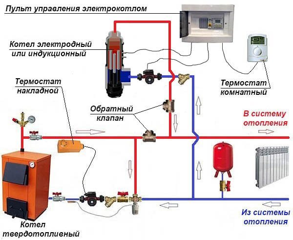
Connection of an electric and TT-boiler with two pumping devices
In a circuit with a buffer tank, it is necessary to install an additional pump, because at least 2 circulation circuits are involved in it - a boiler and a heating one.
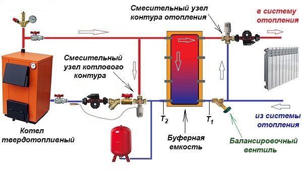
The buffer tank divides the system into 2 circuits, although in practice there are more of them.
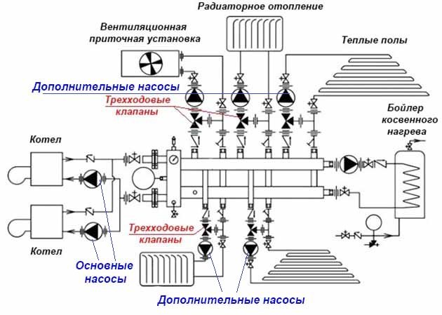
A separate story is a complex heating scheme with several branches, implemented in large cottages on 2-4 floors. Here, from 3 to 8 pumping devices (sometimes more) can be used, supplying the heat carrier floor by floor and to different heating devices. An example of such a scheme is shown below.
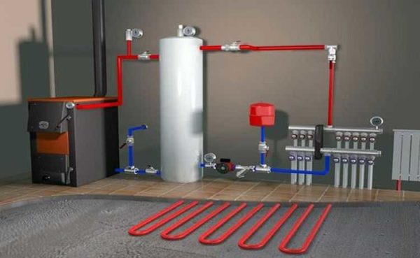
Finally, the second circulation pump is installed when the house is heated with underfloor heating. Together with the mixing unit, it performs the task of preparing a heat carrier with a temperature of 35-45 ° C. The principle of operation of the circuit presented below is described in this material.
This pumping unit makes the heating medium circulate through the heating circuits of the underfloor heating.
Reminder. Sometimes pumping devices do not need to be installed for heating at all. The fact is that most of the wall-mounted electric and gas heat generators are equipped with their own pumping units built into the body.
Name of drawings
The drawings are named as follows. When the scheme is executed at a certain height of the building, it is called "Plan at the 3 thousand mark." Carrying out a drawing for heating a storey gap, he is given the name "PLAN 2-5 floors". A completed drawing of one floor of a house, but on different planes, will be called "PLAN 2-2" or "PLAN 6-6", etc.
Plan of the 2nd floor of a one-pipe system
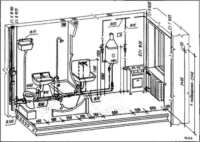
Heating systems and other communication messages (ventilation, air ducts, water supply) are reproduced in one of the types of axonometric projection. This is an isometric frontal view. The components of the systems are indicated by conventional graphic values.
If the length of the OS, air duct, water supply system is large and complexly designed, then they will be shown in the drawing with breaks.
The graphic symbols represent all the components of the heating system. When depicting a heating system, all diameters of pipes of any supply, their degree of inclination (slope), the number of risers and their sizes, and much more are taken into account.
If a heating drawing of an apartment building is drawn up, then the main heating system is displayed only the one that is underground. For the above-ground part of the building, a wiring diagram for heating risers, a wiring of heat-carrying pipes and batteries is drawn up.
Planning in the heating of the ventilation system includes the following indicators: the diameter of the ducts, the volume of air capacity, the number of pipes, and more.
Manholes and openings in the duct or ventilation required for repair work or taking measurements and air samples are also displayed on the general diagram of the heating system. Their brand is also indicated. Heating system drawings should include all sorts of details and features of the pipeline, building, partitions, etc. all this is necessary for the correct subsequent operation of the OS, its repair and other necessary work. It happens that in one building several operating systems are located and function at once. In this case, its number is indicated on the diagram.
The executive scheme for heating is performed not only in general form, but also in section. They indicate the rules for installing the heating system. The use of burdening details in the scheme complicates its perception and reading. That is why sections of parts and their complete drawings are performed in a simplified way, without unnecessary things.
It became quite clear that the presence of drawings showing the structure of the OS in the house is extremely necessary. To carry out such a scheme, you will need to know the generally accepted conventions and letter markings, and have drawing skills. You will need to know this in order to read plans already made by someone, for independent repairs.
Dependent open heating system
The main feature of the dependent system is that the coolant flowing through the main networks directly enters the house. It is called open because the coolant is taken from the supply pipeline to provide the house with hot water. Most often, such a scheme is used when connecting multi-apartment residential buildings, administrative and other public buildings to heating networks. The operation of the dependent heating system circuit is shown in the figure:
At a temperature of the coolant in the supply pipeline up to 95 ºС, it can be directed directly to the heating devices. If the temperature is higher and reaches 105 ºС, then a mixing elevator unit is installed at the entrance to the house, whose task is to mix the water coming from the radiators into the hot coolant in order to lower its temperature.
The scheme was very popular in the days of the USSR, when few people were concerned about energy consumption. The fact is that the dependent connection with the elevator mixing units works quite reliably and practically does not require supervision, and installation work and material costs are quite cheap. Again, there is no need to lay additional pipes to supply hot water to houses when it can be successfully taken from the heating main.
But this is where the positive aspects of the dependent scheme end. And there are much more negative ones:
- dirt, scale and rust from the main pipelines safely gets into all consumer batteries. Old cast-iron radiators and steel convectors did not care about such trifles, but modern aluminum and other heating devices were definitely not good enough;
- due to a decrease in water intake, repair work and other reasons, there is often a pressure drop in the dependent heating system, and even water hammer. This threatens with consequences for modern batteries and polymer pipelines;
- the quality of the coolant leaves much to be desired, but it goes directly to the water supply.And, although in the boiler house water goes through all stages of purification and desalination, kilometers of old rusty highways make themselves felt;
- it is not easy to regulate the temperature in rooms. Even full bore thermostatic valves quickly fail due to poor quality of the coolant.
I-Sketch
The I-Sketch software package is designed for drawing isometric drawings in one line and is the most effective tool for obtaining assembly isometries. It was developed by the English company Alias Ltd, which has been developing software tools for over 25 years that automate the formation of working documentation for the installation of pipelines.
The most famous product of Alias is IsoGen, an isometric drawing generator that is used as a separate module in almost all 3D pipeline design programs. In the case of I-Sketch, the purchase of a generator does not imply any additional investment: IsoGen is included in the software package.
I-Sketch is an application for the Windows operating system and does not require the installation of any additional CAD platform. Other important features of the system include a simple interface and convenient tools for editing the pipeline, which allows you to master the basic techniques in one or two hours, and spend a few days studying the entire software package.
I-Sketch works in Russian, although during installation nothing prevents you from choosing any other: English, French, German, Spanish, Chinese, Czech, Italian ...
I-Sketch databases are open for user editing - special tools are provided for this. A Russian database of products and materials is available, including a wide range of domestic manufacturers. The database of Russian elements is common for I-Sketch and PLANT-4D; a component selection tool is supplied to this database: a specMan Plus generator.
I-Sketch generates documents in AutoCAD DWG and DXF format or in the less common DGN format, which allows using the program in conjunction with any other graphic CAD systems, including Russian developments MechaniCS, SPDS GraphiCS, KOMPAS and T-Flex.
The task in the "native" for I-Sketch PCF format is formed by many design systems, including PLANT-4D, Autodesk Inventor 9 and others.
How I-Sketch works
Working with I-Sketch is generally the same as working with other Windows applications.
The general algorithm is as follows:
- Selecting a database (spec) for the project.
- Drawing a sketch of the pipeline.
- Arrangement of the required dimensions.
- Generation of isometric drawings.
Fig. 5. The diameter of the pipeline can be specified in nominal diameters or in real dimensions (outer diameter)
The most time-consuming stages are sketching and dimensioning: an I-Sketch user usually spends 90% of the time on these stages, that is, on average, about 15-20 minutes (instead of 4-5 hours when working manually). Let's see how this happens.
First, let's load the Russian database.
Having chosen the base, we proceed to drawing the sketch.
First of all, we select the pipe (Fig. 5).
We draw a sketch (Fig. 6): the general view of the pipeline is drawn by points, without observing the dimensions and proportions - only the configuration is important.
← Drawing a line ← Drawing a branch ← Drawing an abutment ← Inserting reinforcement and other details
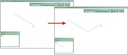
Fig. 6. Drawing a sketch (sketch)
For the convenience of editing, a variety of methods have been developed for displaying service information. For example, different cursor shapes suggest what kind of action will be performed. The color signaling is very clear: green - everything is defined, blue - dimensions are not defined, red - component is not specified.
Convenient I-Sketch tools allow you to quickly identify non-orthogonal areas (Fig. 7, 8).
| Fig. 7. Pipeline sections at an angle | Fig. 8. The pipeline can have any three-dimensional configuration. |
After drawing the general configuration (Fig. 9), one or more coordinate bindings are fixed.Any point of the pipeline can be taken as (0,0,0) or you can specify the real coordinates of the connection - for example, the coordinates of one or more nozzles to which the pipeline is connected (Fig. 10).
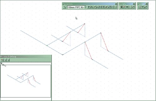
Fig. 9. General pipeline configuration
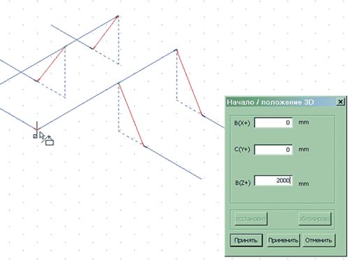
Fig. 10. Set the coordinates we know
Fig. 11. Choosing the nomenclature of the part
The next step is to define the nomenclature of parts (if they were not determined automatically): we set the brands of elbows and tees (Fig. 11). Thus, the lengths of the nozzles of the piping parts will be automatically calculated.
At this stage, you can place reinforcement, as well as other parts, or place dimensions on the sketch. Of course, you can place both on the sketch as needed. In our example, we will first place the dimensions we know - this will simplify further work.
After the dimensions of the sloped sections have been set (Fig. 14), all other dimensions are placed.
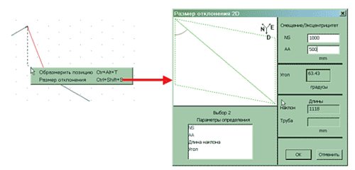
Fig. 12. You can set the values of deviations in general
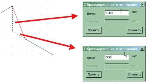
Fig. 13. You can set the values of deviations separately (by projections)
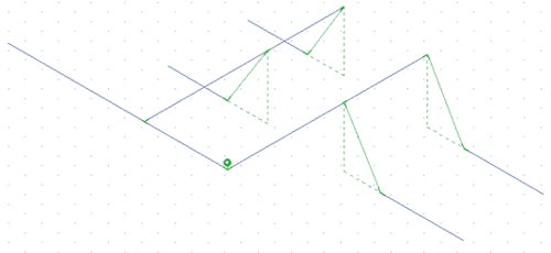
Fig. 14. All slopes measured
Fig. 15. Set the size
A convenient dialog box allows you to quickly set the required dimensions (Fig. 15) - in this case, you can specify both the actual dimensions of the pipe or parts, and the dimensions in the axes. When placing dimensions in the axes, the lengths of the pipes are recalculated automatically.
We have placed all the main dimensions - the pipe has turned green (fig. 16). For a preliminary acquaintance with the results, let's form an isometry (Fig. 17). It will take one to two seconds to generate two sheets.
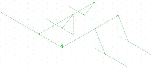
Fig. 16. Dimensioning completed
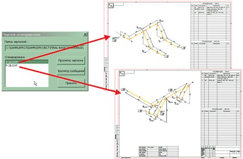
Fig. 17. Drawing an isometric drawing will take less than one second
Next, we place the reinforcement. The ergonomic, user-friendly interface always asks for the necessary information - for example, the location of a valve in a pipeline section. Distances can be set both relative to the axes and relative to the place of abutment to the parts (from the weld). After placement, the reinforcement is selected (however, this operation can be performed at any stage, which is very convenient, since it allows you to easily make changes).
| Fig. 18. Entering distances | Fig. 19. Selecting the brand of reinforcement |
In the same way, we place the supports and other designations of the isometric drawing.
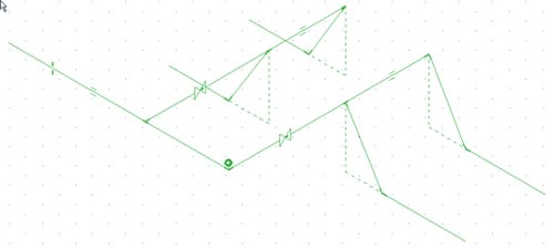
Fig. 20. Completed Piping Sketch
Additional I-Sketch features required
Horizontal sections of pipelines are often made with a slight slope for gravity flow of liquid. Small slopes are inconvenient because they are not very clearly displayed in the drawings, so it is customary to simply mark them (a symbol and the slope are placed) and recalculate the elevations.
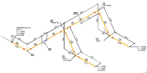
Fig. 21. Isometric drawing, automatically executed from the sketch
In I-Sketch, slopes are set as easily as in manual drawing, but all (!) Coordinates and pipe lengths are recalculated automatically. Thus, according to the drawings received from design institutes, you can quickly sketch out a sketch, arrange positions, and then adjust the state of the slopes.
When placing slopes, I-Sketch takes into account fixed points: if the coordinates of the nozzles to which the pipeline is connected are specified, then when specifying slopes, changes will be made so that these and other stationary points do not change.
You can automatically insert template fragments on a sheet of an isometric drawing: nodes displaying fasteners, welds and other design information from a library of templates (blocks).
In addition, you can automatically place in the drawing the symbols of intersections with walls, floors, flow directions, text labels, distances to structures not shown in the drawing, labels in the drawing stamp, insulation symbols, numbering of welds and much more.
Types of isometric drawings generated by I-Sketch
The user of I-Sketch has the opportunity to customize their formats of assembly isometries: their own designations, completeness of information, availability and composition of specifications.
The content and form of the specification, automatically generated by I-Sketch, is also customizable to the user's requirements. For example, the specification shown in Fig. 22, is identical to GOST, but instead of the usually filled designation of technical specifications, an identifying component is included in the "Designation" column - a user code. Such codes are used at will and, as a rule, are used to identify products in the warehouse.
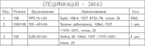
Fig. 22. Sample specification
By default, the I-Sketch software package comes with several pre-configured views of isometric drawings, each of which has its own functional purpose. They can be conventionally divided into three groups: control (survey), alignment (with the designation of pipeline nodes) and assembly isometry. The most interesting isometries of the third group:
- "Editing room. General "
(
FINAL-BASIC
) - this isometric view displays all the details of the pipeline, all dimensions and the necessary designations. - "Editing room. Welding table "
(
FINAL-WELD-BOX
) Is an extended version of FINAL-BASIC. In addition to the standard content of the general installation isometry, the numbering of welds is put down on the drawing and a table with information on the seams is formed. If necessary, a detailed drawing of the assembly is automatically added to the welds (Fig. 23). - "Editing room. Pipe table "
(
FINAL-CUT-LIST
) - an extended version of FINAL-BASIC isometric. The drawing is additionally marked with reference designations in accordance with the pipe table. The latter includes a list of all pipe sections with an indication of diameters, lengths, methods of processing ends and other information (Fig. 24).
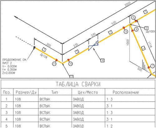
Fig. 23. Fragment of assembly isometry with seam numbering and welding table
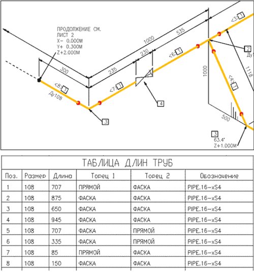
Fig. 24. Fragment of installation isometry with specification and table of pipe lengths
Using I-Sketch as a Basis for Strength Calculations
From the point of view of installation organizations, it is interesting to transfer the design model to the START program, designed to calculate the strength and stiffness of pipelines.
By means of the program, you can assess the strength according to various regulatory documents:
- RD 10−249−98 (Gosgortekhnadzor of the Russian Federation). Steel pipelines of power plants with a pressure of over 0.7 kg / cm2 and a temperature of over 115 degrees.
- RD 10-400-01 (Gosgortekhnadzor of the Russian Federation). Steel pipelines for water heating networks and steam pipelines outside power plants.
- RTM 38.001−94 (Ministry of Fuel and Energy of the Russian Federation). Steel process pipelines with pressures up to 100 kg / cm2 and temperatures from -70 to 700 degrees.
- SNiP 2.05.06−85 (Gosstroy RF). Steel main gas and oil pipelines with pressures up to 100 kg / cm2 and no creep in pipe metal.
The combined use of I-Sketch and the START program allows you to perform strength calculations and justify possible replacement of materials.
Pros of independent systems
Already on the way to the main consumers of the home water supply network, a whole set of preparatory measures is provided to ensure the distribution, filtration and adjustment of the coolant pressure. All loads fall not on the end equipment, but on a heat exchanger with a hydraulic tank, which directly take resources from the main source. Such resource preparation is practically impossible in private when operating dependent heating systems. The connection of an independent circuit also makes it possible to rationally use water for drinking needs of optimal purification. The streams are divided according to their intended purpose and on each line they can provide for a separate level of preparation corresponding to the technological requirements.
Cons of dependent heating systems
Of the negative aspects of the operation of such systems, the following are noted:
- Intensive contamination of working circuits with scale, dirt, rust and all kinds of impurities that may well get into consumer equipment.
- Higher requirements for carrying out repairs. The fact is that dependent and independent heating systems in such cases require the connection of specialists of different levels. It is one thing to make repairs on the main line once a year, and it is another thing to carry out a comprehensive inspection of the elevator unit piping at home on a monthly basis.
- Water hammer is possible. Improper connection of communications or excessively high pressure in the circuit can lead to rupture of pipes.
- Low basic quality of the coolant in terms of composition.
- Complexity of control and management. At technological stations of communal water heating, the process of updating the same shut-off valves is rather slow, hence violations in pressure balances may occur.
Useful Tips
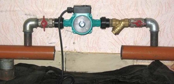
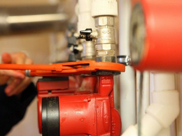
To exclude an arbitrary change in the water flow, shut-off valves are attached in the area of the inlet-outlet of the circulation pump. The connecting nodes must be treated with a "sealant", which will increase the performance of the entire heating system.
To quickly and correctly install the pumping pump, you need selected connections and threads. To reduce the search time for all the necessary parts, look in the plumbing stores for a special device with already selected fasteners. After the completion of the installation process of the pumping unit, the system is filled with water or other coolant.
Before starting the system, open the central valve to remove air locks - water will notify about complete removal of air from the system.
About quantity and breakdowns
The number of circulation pumps required to heat a private house can be determined based on the entire length of the pipeline. If its length is about 80 m, then one is enough. If this length is exceeded, you need to think about increasing the number of pumps in the system.
The reasons for the failure of circulation pumps can be incorrect installation, arbitrary location of the cable and terminal module, as well as non-observance of the rules for operating the heating boiler
To avoid malfunctions, it is important not to ignore the regular air release procedures and take care of good cleaning of the system from mechanical particles.
But it should be remembered that all breakdowns of the circulation pump must be corrected by specialists. Therefore, if faults have already appeared and found, then it is best to contact the repair service.


Where to put
It is recommended to install a circulation pump after the boiler, before the first branch, but on the supply or return pipeline - it doesn't matter. Modern units are made of materials that can tolerate temperatures up to 100-115 ° C. There are few heating systems that work with a hotter coolant, therefore considerations of a more "comfortable" temperature are untenable, but if you feel calmer, put it in the return line.
Can be installed in the return or direct pipe after / before the boiler before the first branch
There is no difference in hydraulics - the boiler, and the rest of the system, it does not matter at all whether there is a pump in the supply or return line. What matters is the correct installation, in terms of strapping, and the correct orientation of the rotor in space
Nothing else matters
There is one important point at the installation site. If the heating system has two separate branches - on the right and left wings of the house or on the first and second floors - it makes sense to put a separate unit on each, and not one common one - directly after the boiler. Moreover, the same rule remains on these branches: immediately after the boiler, before the first branch in this heating circuit.This will make it possible to set the required thermal regime in each part of the house independently of the other, as well as to save on heating in two-story houses. How? Due to the fact that the second floor is usually much warmer than the first, and much less heat is required there. In the presence of two pumps in the branch that goes up, the speed of movement of the coolant is set much less, and this allows you to burn less fuel, and without compromising the comfort of living.
There are two types of heating systems - forced and natural circulation. Systems with forced circulation cannot work without a pump, with natural circulation they work, but in this mode they have a lower heat transfer. Nevertheless, less heat is still much better than its complete absence, because in areas where electricity is often cut off, the system is designed as a hydraulic system (with natural circulation), and then a pump is cut into it. This gives high efficiency and reliability of heating. It is clear that the installation of a circulation pump in these systems is different.
All heating systems with underfloor heating are compulsory - without a pump, the coolant will not pass through such large circuits
Forced circulation
Since the forced circulation heating system is inoperative without a pump, it is installed directly in the break in the supply or return pipe (of your choice).
Most problems with the circulation pump arise due to the presence of mechanical impurities (sand, other abrasive particles) in the coolant. They are able to jam the impeller and stop the motor. Therefore, a strainer-sump must be installed in front of the unit.
Installation of a circulation pump in a forced circulation system
It is also desirable to install ball valves on both sides. They will make it possible to replace or repair the device without draining the coolant from the system. Turn off the taps, remove the unit. Only that part of the water that was directly in this piece of the system is drained.
Natural circulation
The piping of the circulation pump in gravity systems has one significant difference - a bypass is required. This is a jumper that makes the system operational when the pump is not running. One ball shut-off valve is placed on the bypass, which is closed, all the time while the pumping is running. In this mode, the system works as a forced one.
Installation diagram of a circulation pump in a system with natural circulation
When electricity fails or the unit fails, the crane on the lintel is opened, the crane leading to the pump is closed, the system works like a gravity system.
Installation features
There is one important point without which the installation of a circulation pump will require alteration: it is required to turn the rotor so that it is directed horizontally. The second point is the direction of the flow. There is an arrow on the body indicating which direction the coolant should flow. This is how you turn the unit so that the direction of movement of the coolant is “in the direction of the arrow”.
The pump itself can be installed both horizontally and vertically, only when choosing a model, see that it can work in both positions. And one more thing: with a vertical arrangement, the power (created pressure) drops by about 30%. This must be taken into account when choosing a model.
Circulation pump insert
If the pump was not previously included in the heating system. its "tie-in" into the pipeline is required. Since this operation requires some skills and special equipment from the contractor, it can be entrusted to professionals, or you can do the work yourself, having previously familiarized yourself with the technology of installing pipelines.The order of work and the list of equipment used will depend on the chosen tie-in method and pipeline material.
There are 2 ways to insert a circulation pump:
- on the main section of the pipeline;
- on the bypass section (bypass).
Installation of the unit on the main site requires less time and money, but has one significant drawback. The pump operates from the power supply, therefore, with this method of installation, when the light is turned off in an apartment or house, the heating will not be able to function.
The second method is more complicated, but provides the heating system with an increased level of autonomy. In this case, when the system is operating in normal mode, the coolant moves along the bypass channel, and the corresponding section of the main line is blocked using a specially installed ball valve. During a power outage, the valve opens and fluid flows naturally through the pipeline.
Installation diagram of the pump on the bypass channel (bypass).
This option, although common, has one big drawback - a crane on the main highway. It is better if a ball valve is installed instead of a tap.
Installation of a pump on the delivery of a gas floor boiler in a natural circulation heating system. An article on the topic "How to choose a gas boiler" may be useful to you.
In normal operation, the valve is closed by the overpressure created by the pump above the ball. If the pump is de-energized, the ball rises under the pressure of water moving naturally along the line. This option is relevant if the installation of the pump, for one reason or another, is carried out at "supply".
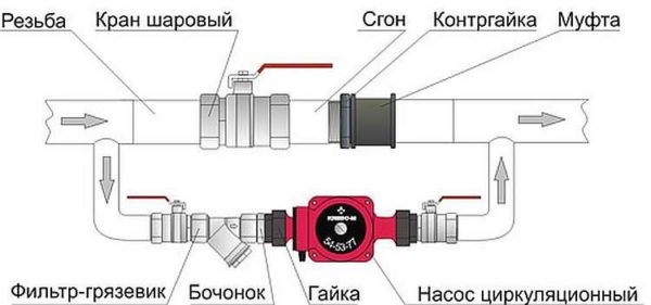
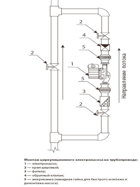
The pump tapping mounting kit includes:
- pipes of the required diameter;
- elements of pipeline fittings;
- union nuts (for polypropylene pipelines) or squeegees (for steel pipes);
- mud filter;
- shut-off valves;
- check valve.
The diameter of the pipes for tapping must correspond to the diameter of the already installed pipeline, and their total length is determined based on the results of measurements at the site of the proposed installation of the pump. The set of pipeline fittings is selected in the same way. Union nuts (or sleeves) are used for quick installation and removal of the pump.
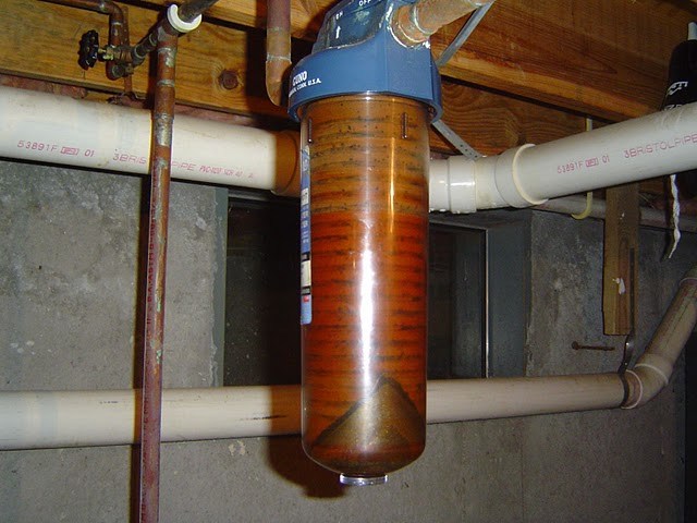
A dirt filter is installed directly in front of the unit inlet. It is necessary to protect the pump from the ingress of contaminants, the source of which can be deposits on the inner surface of the pipelines. The filter drain must point downwards to allow periodic cleaning.
Stop valves are installed at the pump inlet in front of the filter and at the outlet of it, so that, if necessary, the unit can be dismantled without stopping the entire system. When installing the blower on the bypass section, an additional valve is installed on the main line parallel to the pump. The check valve is designed to protect the system from water hammer. It is mounted at the pump outlet in front of the shut-off valve.
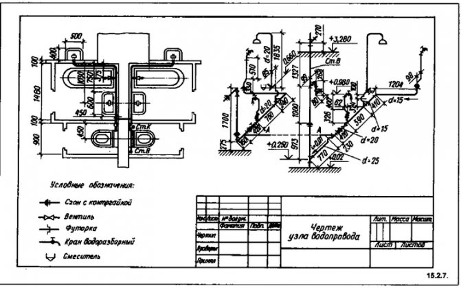
PIPE INSTALLATION DIAGRAM
⇐ Previous Page 6 of 10Next ⇒
The following equipment is shown on the installation diagram of pipelines: shut-off and sectional valves (with piping), transitions of pipe diameters, compensating devices (in large cities it is recommended for use with dу <200 mm U-shaped expansion joints, with dу³200 mm - stuffing box), route turns ( in the absence of connection of subscribers to them, they can be used as L-shaped compensators.The angle must be at least 900 and not more than 1300. Angle of rotation over 1300 must be fixed with a fixed support), water and air drains, fixed supports (movable supports are not shown on the wiring diagram, but the calculation of their number should be in the table), heating units.The completed wiring diagram must include the marking of pipes T1, T2; the size of the diameters on the leader shelves; cross section numbers; binding the track along fixed supports, and when turning the track along its axis and the nearest fixed supports; numbers of intermediate fixed supports; heating unit numbers; numbers of U-shaped compensators (binding of U-shaped compensators from its axis to the nearest fixed supports).
When placing shut-off valves, sectional valves, water and air drains, fixed supports, compensators, one should be guided by the recommendations [1].
The maximum distances between the fixed supports should not exceed the values specified in table 10 [13,14,16,18].
Table 10 - Distances between fixed supports (maximum)
| Dу, mm | Distance between fixed supports, m, with coolant parameters: Prab. In MPa, t in 0С |
| For U - shaped compensators Prab. = 0.8 t = 100 Prab. = 1.6 t = 150 | For stuffing box expansion joints Prab. = 0.8 t = 100 Rrab. = 1.6 t = 150 |
| — | |
| — | |
| — | |
| — |
The distance between the fixed supports of pipelines in self-compensation sections is recommended to be taken no more than 60% of those indicated in the table for U-shaped expansion joints.
| Fig. 9. General view of the wiring diagram of the pipeline |
An example of the arrangement of stuffing box expansion joints: dy> 200
This option requires the installation of many intermediate heat chambers, therefore stuffing box expansion joints are installed 2-sided, thus.
| Figure 6 - General view of the wiring diagram of the pipeline |
Figure 6 - General view of the wiring diagram of the pipeline HYDRAULIC CALCULATION
The task of the hydraulic calculation is to determine the diameters of the heat pipes, the pressure at various points of the network and the pressure (head) losses in the sections. In the course project, when the available pressure on the collectors of the heating plant is not specified, the specific friction losses are taken when determining the diameters in the range of 30-80 Pa / m (3-8 Kgf / m2), and for branches - according to the available pressure, but not more than 300 Pa / m (30 Kgf / m2). The speed of the water should not exceed 3.5 m / s [12,13,14,16].
Head losses in the pipeline section are the sum of linear losses (friction) and head losses in local resistances:
, m (36)
Linear friction losses are proportional to the length of the pipeline and are:
, m, (37)
where lp is the length of the pipeline as planned, m;
R (or DН) - specific frictional pressure loss, daPa / m.
When determining head losses in local resistances, you can use the table of coefficients of local resistances in pipelines of heating networks (see table 11) [14, 20].
Further, according to the nomogram in Figure 14, determine the head loss in local resistances depending on the sum of the local resistance coefficients of the calculated section [12].
Calculation data are summarized in hydraulic calculation table 12.
Table 11 - Coefficients of local resistances in pipelines of heating networks
| Local resistance | Local resistance coefficient |
| The valve is normal | 0,5 |
| Oblique spindle valve | 0,5 |
| Valve with vertical spindle | 6,0 |
| Check valve normal | 7,0 |
| Compensator, stuffing box | 0,3 |
| U-shaped compensator | 2,8 |
| Local resistance | Local resistance coefficient |
| Bends bent at an angle of 900 | |
| R = 3d | 0,8 |
| R = 4d | 0,5 |
| Welded single-seam elbows at an angle of 600 | 0,7 |
| 450 | 0,3 |
| 300 | 0,2 |
| Bends welded double-necked at an angle of 900 | 0,6 |
| The same, three-necked at an angle of 900 | 0,5 |
| Bends bent smooth at an angle of 900 | |
| R = d | 1,0 |
| R = 3d | 0,5 |
| R = 4d | 0,3 |
| Tees at flow confluence: | |
| passage | 1,2 |
| branch | 1,8 |
| Split tee: | |
| passage | 1,0 |
| branch | 1,5 |
| Counter flow tee | |
| Sudden expansion | 1,0 |
| Sudden narrowing | 0,5 |
| Sump | 10,0 |
Table 12 - Hydraulic calculation table
| Uch-ka number | Plot characteristics | Estimated data | |||||
| Water consumption, t / h G | Length according to plan, m l | The sum of the odds places. res. åKm | Diameter, mm dн × s | Water speed, m / s V | Specific head loss, R (DH), daPa / m | Head loss in the area | Sum. on the highway åDH |
| Linear, m.w.c. | Places. m water column | General m.w.c. | S = ΔHuch / G2uch | ||||
| Main highway | |||||||
| Branches |
If the resulting discrepancies are within the normal range, i.e., less than 5%, then the pipelines of the heating networks are linked.
Figure 7 - Nomogram for calculating hydraulic losses in water pipelines with a diameter of 40, 50, 70 and 80 mm (K = 0.0005 m, ρw = 958 kg / m3) [12]
Figure 8 - Nomogram for calculating hydraulic losses in water pipelines with a diameter of 100, 125, 150 and 175 mm (K = 0.0005 m, ρw = 958 kg / m3)
Figure 9 - Nomogram for calculating hydraulic losses in water pipelines with a diameter of 200, 250, 300 and 350 mm (K = 0.0005 m, ρw = 958 kg / m3)
Figure 10 - Nomogram for calculating hydraulic losses in water pipelines with a diameter of 400 and 450 mm (K = 0.0005 m, ρw = 958 kg / m3)
Figure 11 - Nomogram for calculating hydraulic losses in water pipelines with a diameter of 500 and 600 mm (K = 0.0005 m, ρw = 958 kg / m3)
Figure 12 - Nomogram for calculating hydraulic losses in water pipelines with a diameter of 600, 700 and 800 mm (K = 0.0005 m, ρw = 958 kg / m3)
Figure 13 - Nomogram for calculating hydraulic losses in water pipelines with a diameter of 900, 1000 and 1200 mm (K = 0.0005 m, ρw = 958 kg / m3)
Figure 14 -. Nomogram for determining the head loss in local resistances
⇐ Previous6Next ⇒
Recommended pages:

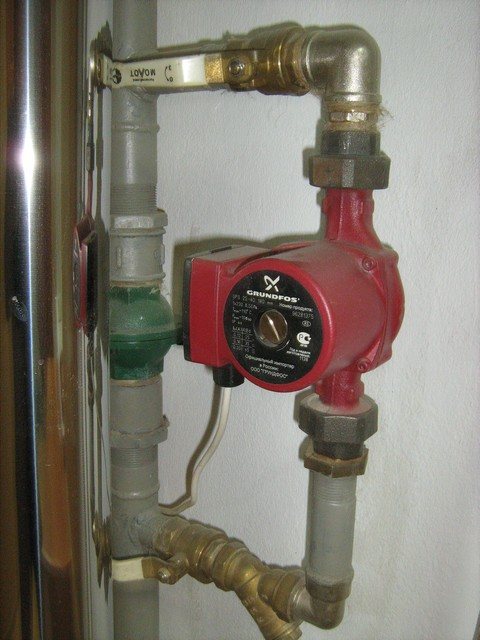
Installing the pump
After the pipeline section is fully prepared, you can proceed directly to the installation of the unit itself. The rotor supports of the pumps used in heating systems are not designed for operation in the vertical position of the unit, therefore only its horizontal arrangement is allowed.
Installing the pump with an incorrect rotor axis.
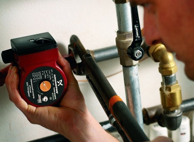
The scope of delivery of the circulation pump includes the unit itself with a built-in or external power supply, gaskets, a passport for the product and instructions for installation and operation. Before starting the installation, you must read the contents of the instructions in order to take into account all the features of the installation process and connection of a specific model. Some pumps are shipped without seals and must be purchased separately.
Installation of a sealing gasket.
If the pump is mounted on a vertical section of the pipeline, then its lower flange is placed on the counter flange of the pipeline, on which the sealing gasket is placed, after which the connection is screwed using the union nut. Then the seal is placed on the top flange of the pump and the connection is screwed on with a second nut. Then the nuts are tightened with a wrench. In some cases, the threaded connections of the pump with the pipeline are additionally sealed with a sealing tape. When installing on a horizontal section, any sequence of flange connections is allowed.
Installation of a circulation pump.
Then it is necessary to open the taps on both sides of the unit so that the internal cavities of the pump are filled with liquid. If the design of the blower does not include an automatic air release valve, it is vented using a special screw that opens the bypass hole.
Tightening the union nut.
After installing the pump in the pipeline, it must be connected to the power supply. The power socket for the unit must be grounded. If the pump provides for the possibility of multi-mode operation, you should switch the lever to the desired mode. The heating circulating pump connected to the power supply begins to perform forced circulation of the coolant, providing more intensive heat exchange and fuel economy of the boiler by reducing the temperature difference of the coolant in the supply and return lines.
Interior solution: decorative grilles for heating radiators
Optimum thermal insulation for heating pipes
Self-insulation of heating pipes on the street
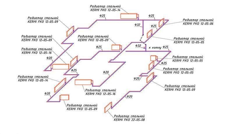
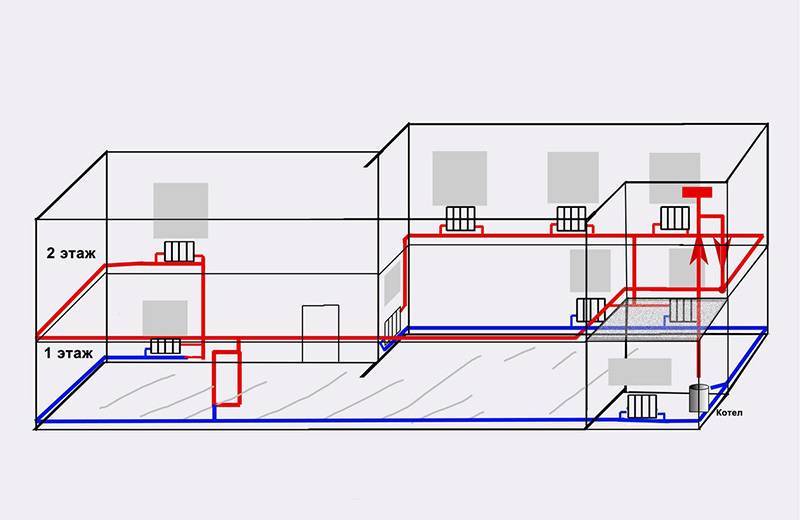
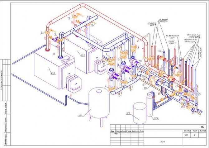
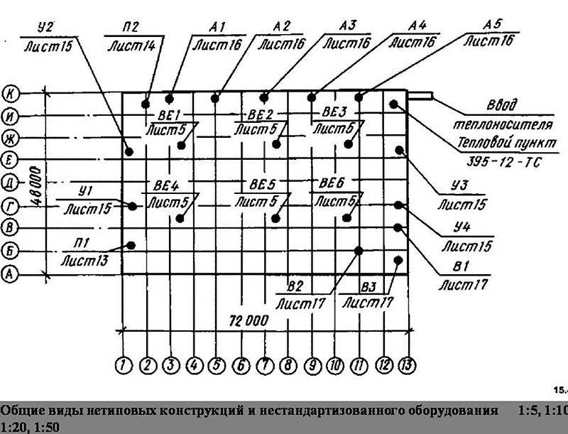
Table 1
| Name | Axonometric diagram | Isometric drawing |
| Drawing display | ||
| Axis arrangement | ||
| Displaying Piping in a Drawing | ||
| Pipes | A symbolic pipe is displayed (pipe sections are not displayed in a pipe assembly) | All pipes are displayed as separate items |
| Armature | Yes | Yes |
| Connections (welds, threads, flanges, sockets, etc.) | Only basic connections are displayed | All connections are displayed, including welds between pipes |
| Flanges | Yes (no specification) | Yes |
| Gaskets (flange connection) | Not | Taken into account in the specification, the designation is placed on the drawing |
| Flanges | Yes (no specification) | Yes |
| Bolted connection | Not | Taken into account in the specification, the designation is placed on the drawing |
| Position marking in the drawing | ||
| Marking of main products and parts according to specification | Yes | Yes |
| Support marking | Not | Yes |
| Weld marking | Not | Yes |
| Flange Gaskets and Fasteners Marking | Not | Yes |
| Pipe marking (by length) | Not | Yes |
| Displaying a BOM in a drawing | ||
| Specification in form 1 GOST 21.104-79 | Yes | Yes |
| Detailed specification taking into account fasteners, supports, welded joints | Not | Yes |
| Splitting the specification by the place of installation (workshop, site) | Not | Yes (if necessary) |
| Welding table | Not | Yes |
| Pipe cutting table | Not | Yes |
The isometric drawing is more difficult to execute and requires more qualifications of the designer. To solve this problem, workstations based on the I-Sketch program are used, which allows you to significantly increase work efficiency and get excellent quality drawings.
Is it possible to convert one system to another
Theoretically, this is quite possible - both in one direction and in the other. Basically, they are just upgrading dependent systems, but there may well be a need to reconstruct an independent infrastructure. At the same time, the most rational option, when it will be possible to preserve the advantages of both systems with varying degrees, will be the implementation of an independent heating system with closed input circuits. This means that the functions that were performed by a separate manifold block with a complete set of control units in the standard independent scheme, in this case, will be taken over by point-installed devices. At different levels of the already home network, before approaching consumers, it is possible to insert filters, compressor units, distributors, circulation pumps and a hydraulic tank.
Liquid properties
Liquids are those substances that are in a liquid state of aggregation. It, in turn, is intermediate between the state of aggregation, solid and gaseous. The liquid also has such a property that is not found in any other state of aggregation: it is capable of changing its shape within practically unlimited limits under the influence of tangential mechanical stresses. In this case, the mechanical stresses can be very small, and the volume of the liquid remains unchanged.
Another important property inherent in all fluids is surface tension. Neither gases nor solids have it, but it is explained by the following reasons: due to the fact that the balance of forces acting on the surface molecules is disturbed, a certain new resulting force directed into the substance appears. This explains the fact that the surface of the liquid is always "stretched". If we consider this situation from the point of view of physics, then it can be argued that surface tension is nothing more than the force due to which the liquid molecules do not move from its surface into the deep layers. It is the force of surface tension that explains the shape of falling drops of any liquid.
Classification
Aggregates are of two types. The first type is dry pumps. In this type of equipment, the coolant and the rotor do not interact with each other.The working part of the rotor is isolated and separated from the motor by stainless steel O-rings. When the rings are started up, a thin water film seals the joints due to the different pressures in the system and in the environment.
The efficiency of a "dry" unit is about 80%. This equipment is very sensitive to water contamination in the system, and if small particles enter, it quickly breaks down. The dry type pump works quite noisy, therefore, when installing it, you should take care of the soundproofing of the room.
"Wet" pumps differ in their design from "dry" ones. Its impeller is located directly in the coolant. The stator and the moving part of the mechanism are separated by a special glass that provides waterproofing of the engine. "Wet" units are cheaper both in operation and in repair, they work quieter than "dry" ones.

The disadvantages of "wet" type equipment include their low efficiency ⎯ only about 50%. This is due to the low sealing of the sleeve separating the stator and the coolant. Although even this performance is quite enough for heating any private house.
Return flow line
The supply and return pipelines must be tested separately according to the strength condition of the fixed supports. [one]
Supply and return pipelines for heating, ventilation, hot water supply systems should be designed separately. [2]
Supply and return pipelines must be laid separately for heating, ventilation, hot water supply and industrial needs. The fulfillment of this condition makes it possible to make the correct calculation of these pipelines and, which is especially important, to organize easy control over the distribution of the circulating labor in individual systems. [3]
The main supply and return pipelines of the heat supply system, to which hot water boilers, water heating installations and network pumps are connected, should be provided as single sectioned or double for boiler rooms of the first category, regardless of the amount of heat consumption and for boiler rooms of the second category - with a heat consumption of 300 Gcal / h and more. In other cases, these pipelines must be single unsectioned. [four]
The main supply and return pipelines of the heat supply system, to which hot water boilers, water heating installations and network pumps are connected, should be provided as single sectioned or double for boiler rooms of the first category, regardless of the heat consumption, and for boiler rooms of the second category - with a heat consumption of 300 Gcal / h (1 26 TJ) and more. [five]
However, the supply and return pipelines of the network are usually laid with the same diameter, although there are cases when it is advisable to lay pipes of different diameters according to hydraulic calculations. [6]
The laying of supply and return pipelines with a diameter of up to 40 mm is allowed (if necessary) in the thickness of the concrete preparation of the floor. [7]
The laying of supply and return pipelines in residential, public and auxiliary buildings, as a rule, should be provided in basements, technical undergrounds or under the floor of the first floor (in the absence of basements and undergrounds), as well as above the floor of the lower floor - with a technical justification. Distribution and collection lines with a diameter of up to 40 mm can be laid in the thickness of the concrete preparation of the floor. [eight]
The laying of supply and return pipelines in residential, public and auxiliary buildings, as a rule, should be provided in basements, technical undergrounds or under the floor of the first floor (in the absence of basements and undergrounds), as well as above the floor of the lower floor with technical justification. Distribution and collection lines with a diameter of up to 40 mm can be laid in the thickness of the concrete preparation of the floor. [nine]
The laying of supply and return pipelines in residential, public and auxiliary buildings, as a rule, should be provided in basements, technical undergrounds or under the floor of the first floor (in the absence of basements and undergrounds), as well as above the floor of the lower floor - with a technical justification. Distribution and collection lines with a diameter of up to 40 mm can be laid in the thickness of the concrete preparation of the floor. [10]
The laying of the supply and return pipelines of heating systems in residential and public buildings and auxiliary buildings of enterprises should be provided (jointly or separately) in basements, technical the justification is also above the ground floor floor. [eleven]
A differential pressure gauge with an induction sensor type DMM-K-YuO is connected to the supply and return pipelines of the local heating system. The pressure drop and water flow rate in the system are related to each other by a quadratic relationship. A change in the water flow rate in the system is sensed by a sensor. The signal received from this sensor is proportional to the differential pressure in the system, if the sensor is linear, the signal is obtained directly proportional to the differential and proportional to the square root of the water flow in the system. A signal proportional to the flow can be obtained using a function sensor. [12]