Private construction is gaining momentum, and with it the demand for modern heating equipment, uninterruptedly providing consumers with thermal energy for heating the house and heating water for household needs.
A gas boiler - central link of the gas heating systemcreated for such purposes. As one of the most economical devices, it nevertheless needs to be adjusted correctly to ensure proper fuel consumption and reliable operation.
Selection and configuration of equipment
The operation of the heat supply system of a private house, in contrast to centralized systems, falls entirely on its owners... And one of the tasks that have to be solved is the issue of the correct selection of gas equipment.
Experience in operating systems shows that a properly selected boiler should work not less than 30% heating period.
The average value of the power consumption of the boiler per square meter of the heated room (with a ceiling height of up to 3 meters) is about 100 watts.
Also, practice shows that the installation of a boiler or burner is too high can create many problemsassociated with excessive consumption of gas, difficulty in selecting the temperature in heated rooms and the reliability of the system.
After the selection and installation of the heating system, as well as at each start-up the following adjustments are made:
- Full heating the boiler.
- Complete gate opening chimney.
- Setting the burner flame at maximum power (the flame should consist of blue and yellow segments).
- Closing the downstream gas valve to remove yellow flame segment.
- Check safety automation and operating modes boiler.
Important! Setting the correct color of the gas burner flame has key for complete gas combustion without the formation of soot settling on the walls of the furnace and chimney, which reduces the efficiency of the system and increases the consumption of gas fuel.
How to adjust the burner power
If the burner significantly exceeds the output of the boiler, it may not enough volume of the furnace, air flow through the dampers and from pressurization. In this case, the combustion of the flame becomes uncontrollable, and the burner flame turns yellow.
Incomplete combustion of gas fuel causes burning of the furnace and chimney combustion products, and part of the energy is dissipated into the surrounding space, increasing fuel consumption.
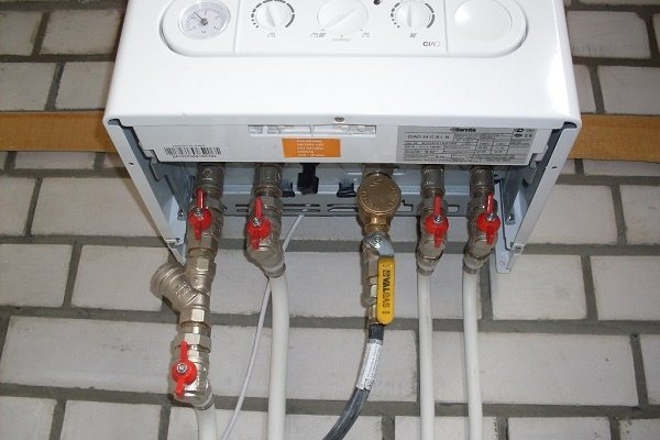
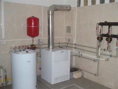
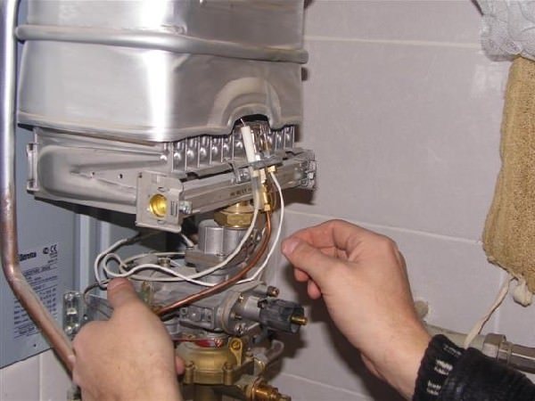
Photo 1. The shut-off valve helps to regulate the gas supply in the event of a malfunction with the boiler.
In this case, the burner power can be reduced. by covering the gas supply valve on the descent.
However, if the power is permanently set to minimum value, this will reduce the efficiency and range of the system.
Reference! When choosing a gas burner, in addition to combustion chamber dimensions and flame geometry, it is important to consider the compliance of the passport values minimum and maximum power and methods of its regulation, as well as the gas consumption of the burner.
High gas consumption
High gas consumption is often caused by inefficient heat exchanger operation boiler. The coolant passing through the heat exchanger carries with it scale and salt particles, which can be deposited on the inner walls of the heat exchanger, reducing its thermal conductivity and increasing the amount of fuel required for heating.
Usually the problem with the heat exchanger manifests itself characteristic noiseemanating from a working boiler, resembling a whistle or gurgle, similar to the boiling of a kettle.
In this case, you will need manual cleaning heat exchanger or its flushing with a special composition.
The reason for the high gas consumption can also be its reduced calorie contentcaused by insufficient drying by the gas distribution company. The norm of the net calorific value of domestic gas should be not less than 7600 kcal per one cubic meter, in practice, the calorific value of the gas can decrease up to 4000 kcal.
Important! When purchasing gas equipment, it is important to take into account composition and minimum gas pressure in a specific gas supply system so that the equipment works stably.
Lack of combustion air
Lack of air for gas combustion can be caused by malfunction of the pressurization system... In this case, you need to check electronic temperature controller settings and boost as well throttle valve.
If the burner ignites with a pop, it may mean that the primary air inlet holes covered or clogged with dust.
In this case, it is necessary to adjust the flame air regulators or clean the holes from dust.
If the flame has a significant yellow segment, it could be caused by defective burner. In this case, the burner power can be reduced by closing the downstream gas valve.
Distinctive features
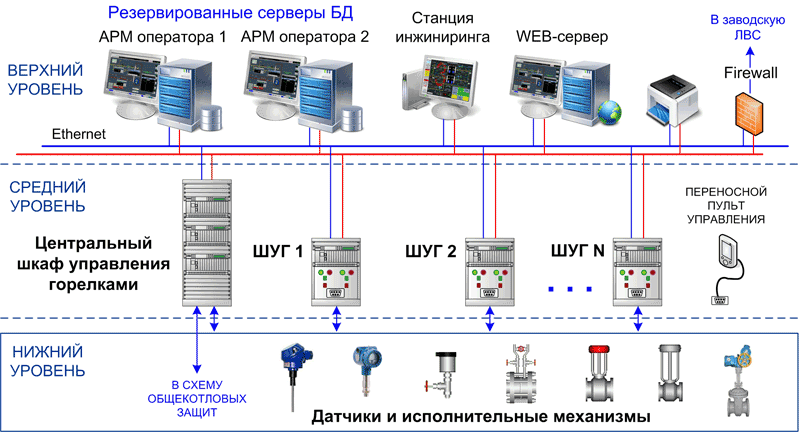
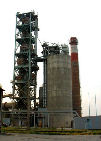
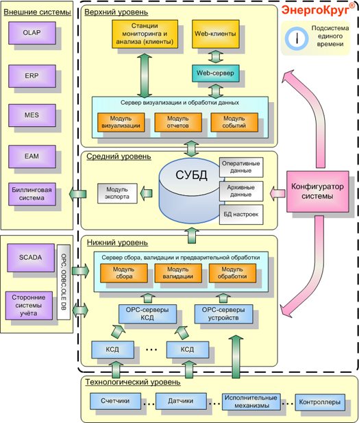
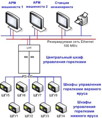
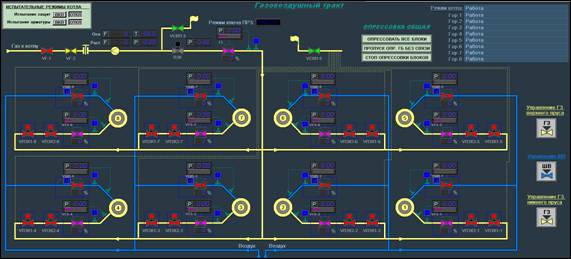
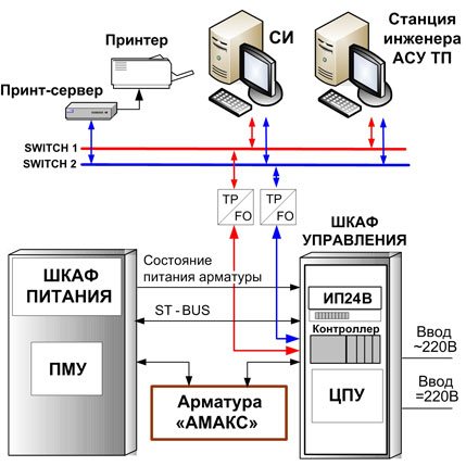
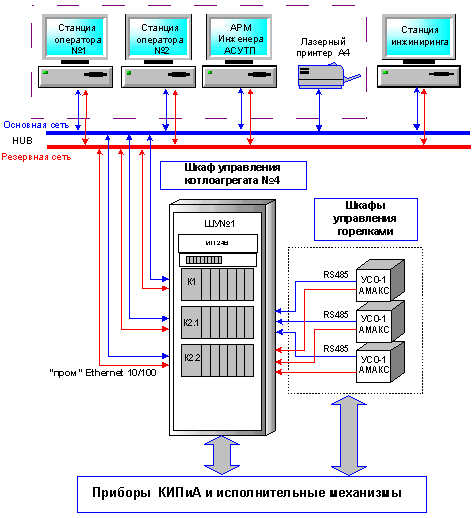
Technical implementation. Burner control cabinets are located near the boiler at the service area. These devices include the whole complex of protection and blocking algorithms necessary for burner control. Depending on the requirements for the subsystem, information capacity, the type of gas equipment used and technological features, the following options for the implementation of the subsystem are possible:
1. SHUG include a microprocessor controller with increased requirements for operating conditions (redundancy functions are possible), which implements algorithms for automatic and remote control of burner valves using the SCADA software "KRUG-2000". Coordination of the operation of all algorithms in the SHUG cabinets is performed by a separate device - the central burner control cabinet (TsSHUG). Information from the SHUG and TsSHUG is transmitted to the database servers. It is possible to implement SAUG as part of the control system of the boiler unit.
2. Algorithms for automatic and remote control of the burner valves are implemented using intelligent input / output modules located in the SHUG. Coordination of the operation of all burners is provided by a microprocessor controller located in the boiler control cabinet (it is possible to implement subsystems of automatic regulation, protection and interlocks of the boiler in this control cabinet). The controller communicates with the SHUG using a duplicated RS485 bus. Information from the controller is transmitted to the database servers.
3. SAUG is located directly in the boiler control cabinet (SHUK). In this case, the ShUK (the entire controller or its input / output modules) is placed in close proximity to the boiler.
Automatic check of gas equipment for leaks and ignition of burners. These tasks, launched by the operator's command, make it possible to bring the processes of pressure testing and ignition of burners in accordance with the current regulatory documents, prevent erroneous actions of personnel, and reduce the time required for these technological operations. The operation of checking the density of the gas fittings of the burners is carried out from the operator's station or on site with the SHUG in automatic mode. The operations of ignition of gas burners and oil injectors are carried out from the operator's station or on site in automatic and manual modes.
Automatic regulation. The automatic controllers provide modern system engineering solutions that ensure the stable operation of burners in various modes of operation. These are various types of balancing, signaling of faults, processing of unreliable parameters, tracking modes, regulation of the gas / air ratio on the burner, etc. In some cases, the SAUG can also perform the functions of regulating the boiler load.
Technological protection. The system of automatic input and output of protections ensures the possibility of normal operation of technological equipment in all operating modes, including starting modes, without personnel intervention in the operation of the protections. Technological protections provide for automatic and authorized manual switching on / off, authorized adjustment of protection settings, control of action and registration of the root cause of operation. The interface part of the subsystem of technological protections and interlocks is made in a form that is convenient for understanding the algorithm and allows you to quickly and efficiently understand the reasons for the action of protection or blocking.
news
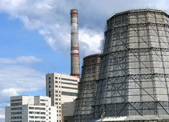
The project of the SAUG boiler TP-47 of the Penza CHPP-1 was developed
An uninterruptible power supply cabinet will increase the reliability of the PTVM-100 boiler at Saransk CHPP-2

The automatic control system of the burners of the boiler unit of the Penza CHPP-1 was modernized
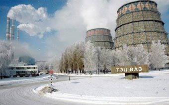
At the TPP of the Volzhsky Automobile Plant, the SAUG of the TGM-84 boiler was successfully introduced
PTK KRUG-2000 controls the PTVM-50 boiler of the Samara SDPP Introduced an uninterruptible power supply system for the burners of the PK-19 and TP-47 boilers of the Saranskaya CHPP-2
At the Ulyanovsk CHPP-1, the technical re-equipment of the SARG of the PK-12 boiler was carried out. CHP-2 The project of the automatic control system of burners (SAUG) of the boiler TP-47 of the Penza CHP-1 was developed At the Saransk CHP-2 the system of automated control of gas burners of the boiler PTVM-100 was put into operation the system of the automatic control of gas burners (SAUG) of the boiler PK-19 Saransk CHPP-2 on the basis of PTK KRUG-2000 At the Penza CHPP-1, the SAUG of the TGME-464 boiler was installed on the basis of the PTK KRUG-2000
The system of automated control of gas burners of the furnace unit of JSC "Uglegorsk-Cement" on the basis of the PTC KRUG-2000 was introduced. The supply of SAUG (automated control system for gas burners) of the boiler unit PK-19 st. No. 3 of Saransk CHPP-2 At Ulyanovsk CHPP-1, 3 automated process control systems for PTVM 100 boilers were successfully put into operation. At the Saransk CHPP-2, an automated control system for gas burners (SAUG) of the PK-19 boiler unit st. No. 2 At Saransk CHPP-2, an automated control system for gas burners (SAUG) of the TP-47 boiler unit based on the PTK KRUG-2000 was put into operation. At the Novokuibyshevskaya CHPP-1, an automated control system for gas burners based on the PTK KRUG-2000 was put into operation. At the Saransk CHPP -2 the automated control system for gas burners of the PK-19 boiler based on the PTC KRUG-2000 was put into operation. The automated control system for the burners of the NZL-60 boiler unit st. No. 2 of the Samara SDPP based on the PTK KRUG-2000
At the Saransk CHPP-2, an automated control system for gas burners (SAUG) of the boiler st. No. 5 on the basis of PTK KRUG-2000
The automatic ignition system for gas burners (SARG) of the TGME-464 boiler, station No. 13 was put into operation at the Ulyanovskaya CHPP-1 Burner control system for the NZL-60 boiler unit of the Samara SDPP was put into operation The automatic control system for the burners of the TGMP-204KhL boiler of the Surgutskaya SDPP-2 branch "JSC" OGK-4 "Automated control systems for gas burners of power boilers at Ulyanovsk CHPP-1 Reconstruction of the gas supply system for power boiler at Ulyanovsk CHPP-1
Information Sheets
Automatic control system for gas burners of the TGME-464 boiler of the Penza CHPP-1 SAUG boiler TGM-84A st.No. 8 TPP Volzhsky auto class = "aligncenter" width = "340 ″ height =" 226 ″ [/ img] SAUG boiler PTVM-50 Samara GRES Automated control system for gas burners of boiler PTVM-100 Saranskaya CHP-2 Automated control system of gas burners of steam boiler PK-19 at Saransk CHPP-2 Full-scale automated process control systems for hot water boilers at Ulyanovsk CHPP-1 Automated control system for gas burners of boiler No. 2 Saransk CHPP-2 Automated control system for gas burners of boiler No. 6 Saransk CHPP-2 Automated control system for gas burners of boiler No. 2 Novokuibyshevskaya CHP-1 Automated control system for gas burners of boiler No. 1 of Saransk CHP-2
Process control system for boilers TGME-464 and KVGM-100 at Severodvinskaya CHPP-2 Automated burner control system for boiler NZL-60 at Samara GRES Automated control system for gas burners at boiler No. 5 at Saransk CHPP-2 Second stage of automation of boilers and gas distribution units at Arkhangelsk CHPP Severodvinskaya CHPP-2
Automatic ignition system for the burners of the TGME-464 boiler st. No. 13 of the Ulyanovsk CHPP-1 Control system for the burners of the NZL-60 boiler st. No. 1 of Samara State District Power Plant Automated control system for boiler burners TGMP-204HL Surgutskaya State District Power Plant-2 Automated control system for gas burners for power boilers at Ulyanovskaya CHPP-1 Automated control system for boiler NZL-110 Samara State District Power Plant
Publications
Experience in the implementation of industrial automation systems at the facilities of the Bashkir Generation)
The system of automated monitoring and control of burners of the boiler unit NZL-60 st. No. 1 of the Samara State District Power Plant (magazine "Automation and IT in Energy")
Automated control system for the NZL-110 boiler of the Samara SDPP based on the PTK KRUG-2000 (ENERGETIK magazine)
Maintenance of gas equipment
Correctly selected and regulated gas equipment may fail from time to time. In order for this to happen as rarely as possible, it is necessary to adjust the system settings in time and carry out the preventive work provided for in the equipment passports.
In order to exclude accidents associated with gas leaks and damage to property and human health, the installation of gas equipment must be carried out authorized organizations (oblgas, raygas, gorgaz) through enterprises licensed to carry out such work.
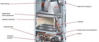
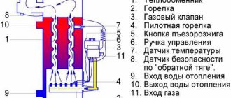
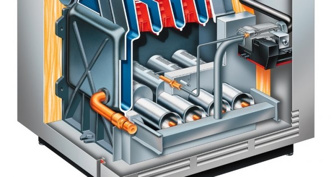
The principle of operation of a gas boiler is based on heating a circulating liquid passing through a heat exchanger. Heat is generated in the combustion chamber as a result of the operation of the gas burner of the heating device. It is from the high-quality setting, and then the operation of the burner, that the productive power of the boiler and its efficiency depend. Let's consider the main aspects of the selection and adjustment of a gas boiler burner in more detail.
Types of gas welding
There are right and left gas welding methods.
Left way
Using the left method, the work is done from right to left. First comes the filler wire, followed by the gas burner. Because of this, the flame is aimed at the edges of the workpieces that have not yet been joined.
This method provides good visibility of the weld, and will ultimately look better than the right method.
This type of work is most often used for low-melting and thin parts.
Right way
This method involves working from left to right. The flame of the gas burner is directed to the already connected area of the parts. In front is the torch that melts the base metal, followed by the filler wire. Due to the fact that the flame is directed at the formed weld seam, it is possible to achieve a lot of positive factors:
- improved protection of the weld pool against oxygen ingress;
- the depth to which the base metal is melted increases;
- the welded seam cools down longer.
With this method of operation, it is possible to reduce heat dissipation. This is due to the limitation of the gas flame: on the sides - by the edges, and in the front - by the welding seam. With the right method, the weld groove angle is 60-70 degrees instead of 90. As a result, the volume of the weld metal is reduced.
With the right method, it is possible to reduce gas costs by 15-20%, and the productivity increases by 20-25% compared to the left.
Carrying out the work in the above way is recommended if the thickness of the jointed workpieces exceeds 5 mm.
How to choose?
What you need to pay attention to when choosing a burner for a boiler:
- productive power - noise level during operation (applies to pressurized models) - type of heating equipment for which the burner is purchased - type of fuel - pros and cons of this device - foresee possible failures in the operation of the local gas supply line.
Taking these factors into account, it is possible to select the most suitable burner device for the boiler so that it works as efficiently as possible without the burden of frequent preventive maintenance.
Combustion chamber of heating equipment
Gas boilers differ primarily in the design of the combustion chamber. It is of two types:
An open chamber is a fairly simple combustion device. It looks like this: a heat exchanger in the form of a coil of thin copper tubes is located above the burner. Thanks to the open design, the air necessary for the combustion reaction is supplied to the ignition site of the gas from the environment.
As a rule, there is enough air from the room (provided there is good ventilation). But there are wall models with air intake from the outside, for which a special hole is mounted in the wall. Open combustion chambers require a chimney.
It is most often installed for models of floor-standing gas boilers, and was also used to complete an old-style boiler (while the ignition was made by an ignition burner).
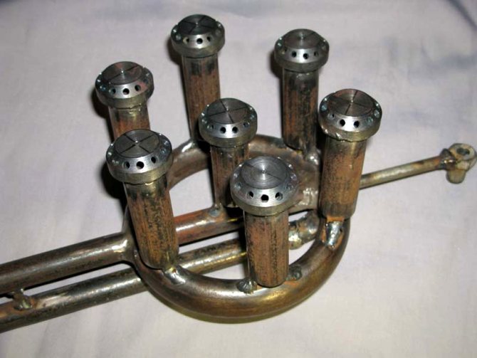
Burner types
According to their constructive, functional differences, burners are divided into:
By appointment:
- for industrial equipment of high power
- for household equipment.
By the type of fuel used:
- devices for natural gas;
- devices for liquefied gas;
- universal devices.
Flame control:
- one-stage - capable of working on / off;
- two-stage (as a variety - models with smooth modulation) - work at full power, when the desired temperature is reached, the flame is halved;
- modulating - boilers with a modulating burner are distinguished by smooth regulation of the flame strength.
By the principle of work:
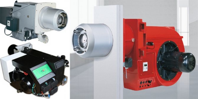
- injection / atmospheric. They work when air is supplied from the room. Fitted accordingly in open combustion chambers. They were also used for boiler models of the old model.

- fan / inflated. They work in insulated type combustion chambers. Combustion air is supplied by a fan. According to their design features, they are divided into: - vortex (round nozzle openings) - direct-flow (shape of a narrow slot of round / rectangular cross-section).
- diffuse-kinetic. Air is supplied in two at the same time: one is mixed with gas fuel, the second is added directly to the chamber during combustion.
Boiler gas burner device
Atmospheric and fan burners differ in their structure. This is due to a different way of supplying oxygen to the chamber during fuel combustion.
Atmospheric burner device.
Air enters the combustion chamber directly from the room. Nozzles are located inside the channel of the burner. Gas is fed into the nozzles, mixing with air, which also has access here. At a short distance from the nozzles, there are outlet slots through which the ready-made fuel mixture is supplied.An area of reduced pressure is created between the nozzles and the outlets, which contributes to the constant injection of mixing air.
The ignition burner is constantly running in the combustion chamber to ignite the main unit.
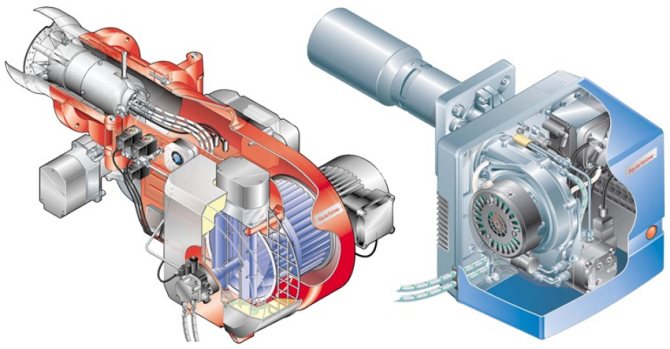
Fan burner device.
The device block consists of:
- engine;
- fan;
- automatic control unit;
- reducer;
- air pressure switch;
- fuel mass mixer.
Air is blown from the outside by a fan and fed into the combustion chamber to form a fuel substance. The air / gas ratio can be adjusted using a damper and a fan.
Burner flame
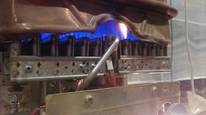
One of the indicators of correct burner operation is the color of the flame. Gas equipment is characterized by an even bluish flame without admixtures of other colors. The presence of blotches of yellow, red indicates that the burner does not work well, this reduces the efficiency of the heating equipment.
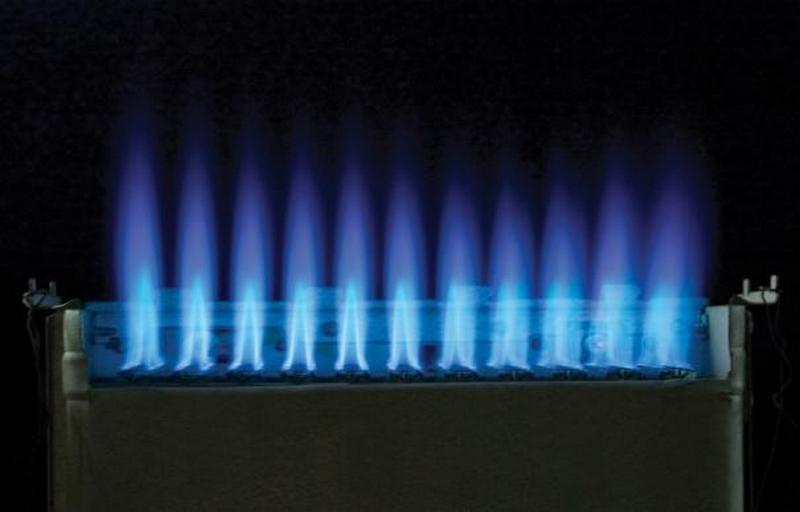
First of all, this concerns injection burners, but sometimes it is also typical for fan burners. The flame may simply not have enough oxygen. Also, dust and other small debris can get along with the air, which will clog the device, reducing the efficiency of the boiler. All this directly affects the flame. If it hums, the burner is working loudly, the fire has changed color - it is necessary to adjust the correct operation of the device.
Goals and objectives of SAUG
- Providing operational personnel with timely, reliable and sufficient information about the progress of the technological process and the condition of the main equipment
- Bringing the technological process of controlling the burners of the boiler unit in accordance with the current regulatory documents
- Implementation of algorithms for automatic testing of gas equipment tightness and ignition of burners
- Coordination of burner operation algorithms
When do you need to adjust the burner flame?
Atmospheric gas burners for heating equipment fail more often. It is equipped with both wall-mounted and floor-standing boiler models. An injection burner of floor-standing equipment reduces its efficiency for various reasons:
- Burner output is too high. It happens when a high power burner is purchased for small heating equipment. At the same time, there is not enough space for combustion, the flow of air for such a power is weak, which leads to the transition of the flame from blue to yellow, the burning of the combustion chamber, chimney.
- If the chimney is poorly cleaned, the draft of the boiler deteriorates. In this case, the waste products of combustion are poorly removed, the flow of air is small. This worsens combustion, the flame turns yellow.
- A defect in the burner itself does not make it possible to correctly adjust the complete combustion of the fuel.
- Due to pressure drops in the gas supply system, well-regulated equipment can discharge large quantities of unused gas into the chimney. In part, it settles in soot, soot. A large layer of soot reduces traction, increases fuel consumption.
- Start-up of heating equipment after repair.
- The presence of extraneous noise during the operation of the boiler, gas burner.
- Change of fuel type.
Equipment setup
Floor standing gas boilers with atmospheric burners can be adjusted independently. The pressurized systems are regulated by an automatic control unit and do not require additional adjustment.
Scheme of actions when setting up single-stage equipment:
- Install the device on the boiler.
- Connect to gas connection.
- Check for absolute tightness.
- Remove the burner housing.
- Using a pressure gauge, measure the gas pressure at the inlet.
- Connect to electricity. Make sure that the jumpers, phases are connected correctly.
- Place a gas analyzer in the chimney.
- Start the device.
- Use a pressure gauge to read the pressure at the outlet of the burner block.The pressure readings must correspond to the parameters indicated in the data sheet.
- Adjust the air supply with an air damper.
- The readings of the gas analyzer must also comply with all standards for the installation of gas equipment.
Functions
- Remote control of the electrified burner fittings and the spark discharge device in compliance with all interlocks and local protections in accordance with current standards and regulations
- Automatic leak test of the burner fittings
- Automatic execution of burner ignition operations
- Semi-automatic ignition with step-by-step execution of operations using intermediate commands from remote controls (from the operating panel, from the controls in the burner control cabinet (SHUG) or from the operator's workstation)
- Gas pressure regulation in front of the burner
- Burner gas-air ratio control
- Diagnostics and indication of the reason for the shutdown of the gas supply to the burner
- Control of the electric shut-off valves of the oil burner path (for gas-oil burners)
- Coordination of SHUG operation during automatic ignition of burners
- Integration into the control system of the boiler
- Collection, registration, visualization and archiving of information (when implementing a subsystem without creating an automated process control system for a boiler unit)
Types of gas burners
Gas boilers differ in the type of combustion chamber. There is an open firebox - which must be equipped with a chimney to remove combustion products. Air for the combustion process in an open firebox comes from the environment. Therefore, units with such a combustion chamber are installed in a dedicated combustion chamber.
Gas boilers with a closed firebox differ from the open version. The burner is located inside a closed housing. The air intake to the burner and the fume extraction to the outside is ensured by a small coaxial chimney.
Gas burners are distinguished by the type of fuel on which they operate:
- for natural gas;
- for liquefied fuels;
- universal.
Most gas boilers are equipped with a universal burner that can operate on both natural and liquid fuels.
By the number of power levels, burners are divided into:
- single-stage - capable of operating in only one mode;
- two-stage - have two power levels;
- modulation - capable of smoothly adjusting the flame strength in several modes.
Reception of fuel gas and ignition of burners
Remove the plug on the fuel gas line according to the issued permit for carrying out gas hazardous work of group I and accept fuel gas for the installation in agreement with the senior operator of the hydraulic fracturing of the motor fuel production (tel. 36-64), the PMT dispatcher (tel. 43-36) and dispatcher PSM. Through the pressure regulator valve pos. 97 at the outlet of the T-11 heater: give steam to the T-11 coil and heat the fuel gas to a temperature of 100-120 ° C, turn on pos. 310 for level measurement in T-11.
When taking gas, make sure that pipelines and fittings are tight.
Prepare an igniter to ignite the burners.
Include in operation all control devices, alarms, interlocks, provided for by the technological regulations.
The stove must be ignited by two people in overalls, safety shoes, a helmet, protective
glasses, having gas masks with you. Fire up the pilot burner in the following sequence:
- close the steam for steaming the oven chambers;
- remove the plugs from the burner;
- open the register at the burner and insert the burning igniter to the burner mouth;
- slowly open the valve on the gas supply to the burner and light it;
- follow the pressure of the fuel gas in front of the burner on the pressure gauge;
- make sure that the gas burns steadily, remove the torch from the burner, extinguish it in a box with sand;
- adjust the air flow by turning the burner air register;
After stable combustion of the pilot burner has been established, light the main burner from it:
- Slowly open the valve in front of the burner to supply gas and making sure that it ignites, immediately start air supply with the manual air supply regulator, then increase the supply of gas and air, adjust the combustion flame.
- The next burner should be ignited only after the previous burner has been burned. Ignition of one burner from another, located nearby.
The burners are ignited symmetrically on the bottom and top rows of the furnace.
During the period of ignition of the furnace burners, interlocks must be turned on to close the automatic shut-off devices on the gas supply lines to the burners when its pressure drops, as well as when the product is stopped in the furnace coil.
Removal of plugs and ignition on gas should be carried out alternately. When firing up the burners, stand to the side of the nozzle window, being careful not to eject the flame.
If the igniter flame has gone out before the burner is ignited, it is necessary to immediately stop the gas supply to the burner, remove the igniter from the furnace, eliminate the malfunction and ventilate the furnace and gas ducts for 20-30 minutes.
After that, you can proceed to re-ignite the burner.
Use a sparking tool when removing the plugs. When firing up the burners, have a steam hose ready in case gas condensate gets out under the burners.
Control over the drying mode by thermocouples showing the temperature at the passes of positions TRASH-451, 461, 452, 462, 453, 463.
During the drying period, it is necessary to ensure an even distribution of temperature throughout the entire volume of the oven.
The rise in temperature on flows through the coil P-1, P-2, P-3 is carried out at a rate of 100C per hour (pos. 13, 12, 11)
- Maintain the system at a temperature of 1500C for 24 hours to evaporate the water;
- Perform hot-tightening of flange joints at a temperature of 150 ° C.
- Raise the temperature to 250 ° C. Keep at this temperature for 24 hours.
- Rise of temperature at the outlet of P-1, P-2, P-3 to 450 0C at a rate of 15-25 0C / hour.
- Maintain a temperature of 450 ° C for heating the reactors for 4 hours to remove adsorbent moisture.
- Reduce the temperature to 150 ° C at a rate of 15-25 ° C / hour (pos. 13, 12, 11)
Before starting work on drying the furnaces, the installation manager instructs the maintenance personnel on the maintenance of the drying regime and safety rules for the operation of the furnaces, a schedule is drawn up for round-the-clock duty of the personnel who carry out the drying process and employees of the instrumentation and automation service, locksmiths, electricians.
After the end of drying, the furnaces are brought back to normal technological mode. Control of the drying process of the system is carried out by the flow of water in the separators E-1/1, 2, 3 and from the drain E-16 into the sewerage system.
Stand to the side of the burners during ignition.
If the burner does not light up or goes out, it is necessary to close the fuel gas supply, ventilate the furnace and gas ducts for 20-30 minutes, find out and eliminate the cause of the flame extinguishing. Repeat ignition. If the burner does not ignite after three attempts, it is necessary to purge the combustion chamber of the furnace with steam again and re-ignite the burner in the above order. Extinction is possible due to the presence of an inert gas in the composition of the fuel gas at the initial moment of shuraing the furnace, therefore, constant monitoring of the combustion of gas burners after their ignition is mandatory.
If condensate enters with the gas, it is necessary to close the valves to the burners, drain the condensate into the flare line from the installation. It is possible to burn out gas condensate through a burner distant along the gas path, with constant control and constant maximum possible increase in the temperature of the fuel gas in the T-11 due to an increase in the coolant supply.
After firing up the burners, adjust the vacuum in the combustion chamber with a slide gate.
Drying schedule.
During the drying period, it is necessary to ensure an even distribution of temperature throughout the entire volume of the furnace and the removal of water vapor from the working space of the furnace by means of natural ventilation open (hatches).
The control of the drying mode is carried out according to the readings of the thermocouples of the temperature of the flue gases at the pass of the furnace.
The rate of temperature rise is carried out in accordance with the following regulations, and is the maximum allowable:
- heating up to 100-105 ° С at a rate of 10 ° С per hour;
- exposure at 100-105 ° С for 24 hours;
- heating up to 150 ° С within 24 hours;
- exposure at 250 ° C for 32 hours;
- heating up to 250 ° C at a rate of 10 ° C per hour by sequential symmetrical ignition of additional burners (if necessary, ignite the main burners).
Constantly monitor the stability of the flows through the coil. Exposure at 250 ° C - 50 hours.
- heating up to 250 ° С at a rate of 10 ° С per hour
- exposure at 450 ° C for 2 hours, then lowering to the temperature required for those. mode at a speed of 10 ° C per hour.
Loading catalyst and elemental sulfur.
Preparing the catalyst for work.
All operations for loading the catalyst and sulfur into the reactor should be carried out in dry weather or measures should be taken to prevent moisture from entering the catalyst.
The loading of ceramic balls, catalysts and elemental sulfur is carried out according to the loading diagram in the following order (from bottom to top):
- down the reactor are loaded ceramic balls with a diameter of 20 mm 100 mm above the level of the plane of the working table or the catalyst of the protective layer;
- ceramic balls with a diameter of 10 mm with a layer of 150-200 mm or a protective layer catalyst;
- on top of the ceramic balls or the catalyst of the protective layer, the catalyst of the main layer is loaded;
- elemental sulfur for sulphiding is loaded into the reactor mixed with a catalyst in an amount of 10% of the total weight of the catalyst
- mixing of the catalyst with sulfur is carried out as it is loaded in the loading hopper;
- over the catalyst of the main layer load ceramic balls with a diameter of 10 mm with a layer of 150 mm or a catalyst of the protective layer;
- ceramic balls with a diameter of 20 mm with a layer of 150 mm or a protective layer catalyst;
Loading of ceramic balls, catalysts of the main and protective layer, elemental sulfur is carried out by the sleeve method.
After the completion of the work on loading the catalyst, closing the hatches and removing the plugs, work is carried out to prepare the catalyst for operation, which includes the following operations:
- purging the system of the reactor block with nitrogen at a pressure of 1.5 kgf / cm2 to the oxygen content in the in. gas no more than 0.5% vol. at the exit from E-2/1 (2,3) with pressure relief on the spark plug within 1 hour;
- pressure testing of the reactor block with nitrogen at a pressure of 37 kgf / cm2 with subsequent release of nitrogen pressure on the spark plug to 1.5-2.0 kgf / cm2 to eliminate gaps;
- intake of WASH into the system with a hydrogen concentration of at least 78% vol. to release the system from the residual nitrogen content of not more than 0.5% vol. at the outlet of the reactor and setting up the circulation of the WAG at an operating pressure (30-31 kgf / cm2) on the flow;
Catalyst passivation.
To ensure safety when opening the reactor in order to unload the catalyst, passivation is preliminarily performed to remove pyrophoric deposits in the catalyst. Passivation consists in the oxidation under mild conditions of the compounds that are flammable in air and contained in the catalyst. After that, the catalyst practically loses its pyrophoric properties.
The passivation process is carried out in the following order:
- at the operating parameters of the hydrotreating process, stop accepting raw materials for the flow;
- circulate the HSG with a flow rate of 3000 m3 / h until the complete cessation of liquid separation in separators E-1/1, (E-1/2, E-1/3), E-2/1, (E-2/2, E-2/3) through the drains (desorption of raw materials);
- raise the temperature of the WASH at the outlet of the furnace to 4900C at a rate of 20-250C / hour;
- to calcine the catalyst within 48 hours at an HSG temperature at the outlet of the furnace 4900C, at a pressure in the reactor block of at least 30 kgf / cm2 and a HSG flow rate of 5000 m3 / h;
- to reduce the temperature of the top of the reactor to 1500C at a rate of no more than 20-250C an hour;
- shut off the supply of WASH to the corresponding flow, release the pressure from the system, drain the residual oil product;
- take nitrogen into the system, raise the nitrogen pressure to 1.5-3.0 kgf / cm2;
- purge the process flow with nitrogen until the residual hydrocarbon content in the outlet gas is no more than 0.5% by volume. within 2 hours for a torch and within 22 hours for a candle;
- to purge the reactor block with live steam onto the candle for 14 hours;
- supply nitrogen to the reactor and, due to the nitrogen flow, reduce the temperature in the reactor to 31-400C;
- Installation of plugs, opening of reactor hatches should be performed at a minimum nitrogen consumption and a reactor temperature of 30-400C;
Regeneration of the catalyst.
During the hydrotreating of residual fractions, the activity of the catalyst can drop sharply due to the deposition of metals and organometallic compounds contained in the feedstock in its pores. The regeneration of catalysts is carried out in the case when the decrease in the activity of the catalysts cannot be compensated for by changing the parameters of the technological regime within the limits stipulated by the norms of the technological regime.
It is recommended to carry out the regeneration process outside the reactor of the technological unit on a specialized regeneration unit. Oxidative regeneration of the catalyst consists in burning out the formed coke deposits. In this case, each of the streams is turned off, the catalyst is passivated and discharged from the reactor into a container to be sent from the unit for regeneration.
Only gas-air regeneration is allowed.
Previous4Next
How to set up a gas burner?
It is recommended to adjust the gas boiler of the burner flame using a gas analyzer. It records the indicators of air that is involved in the combustion process: CO concentration, oxygen level, excess air ratio. The CO concentration should not exceed 50 ppm, oxygen is normally in the range of 3.6-5.3%. A lower oxygen content will lead to the fact that the fuel does not burn completely, a higher one - to a high concentration of CO2. Excess air can lead to an explosive situation, and its lack of air can lead to incomplete combustion of fuel, the formation of soot, soot and low efficiency.
The strength of the fire can be observed through the viewing hole. The orange flame is too large, you can turn it down until it becomes almost invisible and has a bluish tint. Such a fire ensures the optimal operation of the gas boiler. If you reduce the flame even more, then it will become completely invisible, and then it will go out.
The regulation of the starting fuel supply works only at the moment of ignition and does not affect the efficiency of work. But if desired, it can also be adjusted: it is necessary to gradually reduce the starting feed, turning on the burner until it stops lighting up; then you need to increase the starting feed by turning the regulator in the opposite direction. The adjustment ends by checking the burner start-up.
If the flame burns with noise, reduce it with the regulator.
Why does a gas boiler smoke - reasons and methods of solution
Gas welding modes
The selection of the gas welding mode depends on many factors.
First you need to choose the right gas burner. It mixes oxygen and acetylene in the required proportions. With its help, the flame level is adjusted by adjusting the supply of combustible gases.
There are burners without injection and with the presence of an injector. In practice, injection is most often used. In such burners, the combustible gas is supplied at low pressure to the mixing chamber, where it is injected with an oxygen jet.
Welding flame power
The burners differ depending on the flame power:
- D1 - micro-low power;
- G2 - low power with acetylene consumption parameters 25-700 l / h and oxygen consumption 35-900 l / h;
- G3 - average power, assuming the supply of acetylene 50-2500 l / h, and oxygen 65-3000 l / h;
- G4 - increased power.
The power of the welding flame is determined by the level of acetylene consumption. It is necessary to select the power based on the melting temperature of the metal being welded, its thickness, as well as thermal conductivity.
To calculate the power, the formula is used: Q = A * h:
- acetylene consumption is denoted - Q and is measured in m3 / h;
- metal thickness is measured in millimeters and denoted by h;
- letter A denotes a coefficient describing the consumption of acetylene per 1 mm of welded material... For steel, the coefficient is 0.10 - 0.12, for cast iron - 0.15, for aluminum - 0.10.
Based on the ratio of oxygen and acetylene directed into the burner, three types of flame are distinguished: neutral, oxidizing and carburizing. Depending on the required properties of the deposited metal, the appropriate type of flame is selected. Most often, a neutral flame is used, which provides the highest mechanical properties of the weld metal. Other types of flame are rarely used. For example, for easily oxidizing metals, a carburizing flame is used.
Welding speed
When gas welding, the speed of the work must be observed.
To calculate the speed, the formula is used: V = A / S, where:
- V - speed of work, measured in meters per hour;
- S - metal thickness in millimeters;
- BUT - a special coefficient that takes on different values depending on the type of metal and its thickness.
Filler wire diameter
Welding wire, various rods or metal granules can be used as filler material. The filler material diameter is calculated using the following formulas:
- d = S / 2 + 1 - with the left welding method;
- d = S / 2 - with the right welding method.
If the diameter of the welded metal exceeds 15 mm, then the diameter of the filler material must be at least 6 mm.
There are some guidelines for welding different metals. For example, in gas welding of steels, high quality work can be achieved by using manganese and silicon-manganese wires of the following grades: Sv-08GS, Sv-08GA, Sv-10G2.
For welding of cast iron, rods of grades A and B are used. Grade A is used in hot welding when heating the entire product. Grade B is used in welding with local heating.
Converting the burner to another type of gas
Only universal burners can be easily adapted to another type of fuel and do not require replacement of component parts. The rest of the burners need to replace the ramp, diaphragm, nozzles or manifold in order to switch to a different type of gas. With the help of a ramp, you can regulate the gas supply in fairly wide ranges. In some cases, it is possible to adjust a burner operating on one type of fuel to burn on a different type of gas. For example, switch from propane to methane and vice versa. When replacing propane with methane, the starting feed is first increased to ignite the gas and then gradually reduced as detailed in the previous section.
The methane burner, when switching to propane at the start-up with maximum fuel supply, will smoke. It is regulated by gradually decreasing the fuel supply.
When converting a burner from one type of fuel to another, it should be borne in mind that the specific heat of combustion of propane is 1.5 times higher than that of natural gas - methane. So the capacity of a propane gas burner without replacement of elements will increase. For example, a gas boiler with a power of 10-30 kW, when converted to propane, is capable of delivering a capacity of 15-45 kW. However, the burner will not be able to generate more than 30 kW for a long time, as it will quickly overheat and fail. Therefore, the operating power range of the unit will be 15-30 kW.
When converting a similar boiler from propane to methane, the capacity will decrease and amount to 6-18 kW.
7.56.Before starting the boiler (repair, reserve more than 3 days), the serviceability of blowing machines, auxiliary equipment, measuring instruments and remote control, regulators, as well as the serviceability of protections, interlocks, alarms, warning devices and operational communication are checked, the operation of the shut-off valve of the boiler and burners with construction on actuators.
If the boiler is idle for less than 3 days, only measuring instruments, equipment, mechanisms, protection devices, interlocks and alarms, on which the repair was carried out, are subject to verification.
The identified faults must be eliminated before the boiler is fired up. If a malfunction of the protective equipment and interlocks acting on the shutdown of the boiler is detected, the boiler is not allowed to ignite.
7.57. The start-up of gas into the gas pipeline of the boiler after conservation or repair should be carried out with the smoke exhausters, blowing fans, recirculation exhausters switched on in operation in the sequence specified in the boiler operation manual.
7.58. It is not allowed to blow through the boiler gas lines through safety lines or through the boiler gas burners.
7.59. Before firing up the boiler from a cold state, a pre-start check of the tightness of closing the shut-off devices in front of the boiler burners, including the shut-off valve of the boiler and burners, should be carried out with the draft mechanisms turned on.
If a leak is detected in the shut-off devices, the boiler is not allowed to light up.
7.60. Immediately before firing up the boiler and after stopping it, the furnace, the flue gas ducts of the boiler combustion products, the recirculation systems, as well as the closed volumes in which the collectors ("warm box") are located, must be ventilated with the inclusion of all smoke exhausters, blow fans and recirculation fans during not less than 10 minutes with open dampers (valves) of the gas-air duct and an air flow rate of not less than 25% of the nominal.
7.61. Ventilation of boilers operating under pressure, as well as hot water boilers in the absence of a smoke exhauster must be carried out with the blowing fans and recirculation exhausters turned on.
7.62. The boilers must be fired up with the blowing fans and smoke exhausters running (where provided).
7.63. Before firing up the boiler, if the gas pipelines were not under excessive pressure, the oxygen content in the boiler gas pipelines should be determined. If the oxygen content is more than 1% by volume, the ignition of the burners is not allowed.
7.64. The ignition of boilers, all burners of which are equipped with a safety shut-off valve and a safety shut-off device, can be started by lighting up any burner in the sequence specified in the boiler operating instructions.
If the first melted burner does not ignite (extinguish), the gas supply to the boiler and the burner must be stopped, its ZZU is turned off and the burner, furnace and gas ducts must be ventilated in accordance with the requirements of these Rules, after which the boiler can be fired up on another burner.
Re-ignition of the first burner to be fired must be carried out after elimination of the causes of its non-ignition (extinguishing).
In case of non-ignition (extinguishing) of the torch of the second or subsequent melted burners (with stable combustion of the first one), the gas supply to this burner must be stopped only, its ZZZ is turned off and its ventilation carried out with a fully open shut-off device on the air duct to this burner.
Its re-ignition is possible after elimination of the causes of its non-ignition (extinction).
7.65. If all burners are turned on during ignition, the gas supply to the boiler must be immediately cut off, their ZZU disconnected, and the burners, furnace, and gas ducts must be ventilated in accordance with the requirements of these Rules.
The boiler should be re-fired after finding out and eliminating the reasons for the extinguishing of the torches of the burners.
7.66.The procedure for converting the boiler from pulverized coal or liquid fuel to natural gas should be determined by the operating instructions for the boiler, approved by the chief engineer (technical director) of the organization.
In case of a multi-tier arrangement of the burners, the burners of the lower tiers should be switched to gas first.
Before the scheduled transfer of the boiler to gas combustion, a check should be carried out of the shut-off valve actuation and the operability of technological protections, interlocks and alarms of the boiler gas supply systems with an impact on the actuators or on a signal in an amount that does not interfere with the operation of the boiler.
7.67. The gas supply to the boiler gas pipelines must be immediately stopped by the operating personnel in the following cases:
failure of technological protection;
explosion in the furnace, gas ducts, heating (visually) of the supporting beams of the frame or columns of the boiler, collapse of the lining;
fire threatening personnel, equipment or remote control circuits included in the boiler protection scheme;
loss of voltage on remote and automatic control devices or on all control and measuring devices;
destruction of the boiler gas pipeline.
7.68. In the event of an emergency shutdown of the boiler, it is necessary to stop the gas supply to the boiler and all burners of the boiler, their ZZU, open the disconnecting devices on the safety pipelines.
If necessary, open the shut-off devices on the purge gas pipelines and ventilate the furnace and gas ducts in accordance with the requirements of the Rules.
7.69. In case of a planned shutdown of the boiler to transfer to the standby mode, the gas supply to the boiler, burners, ZZZU must be stopped, followed by their shutdown; disconnecting devices were opened on safety pipelines, and, if necessary, on blowdown gas pipelines; ventilation of the furnace and gas ducts was carried out.
At the end of the ventilation, the blowing machines must be turned off, the manholes, hatches, the gate (valve) of the gas-air duct and the guide vanes of the blowing machines must be closed.
7.70. If the boiler is in reserve or runs on another type of fuel, plugs after the shut-off valves on the boiler gas pipelines may not be installed.
Excessive gas pressure in the gas pipelines of the boiler is allowed when operating on other fuel, provided that the tightness of the closing of the disconnecting devices in front of the boiler burners is ensured.
7.71. Monitoring of hydraulic fracturing equipment, readings of measuring instruments, as well as automatic signaling devices for monitoring gas contamination should be carried out using instruments from the control panels of the boiler and turbine shop (KTC) and the hot water boiler room, from the local control panel of the hydraulic fracturing station and visually at the site, during rounds.
7.72. The disconnecting device in front of the PSK in the hydraulic fracturing must be in the open position and be sealed.
7.73. The reserve reducing line in the hydraulic fracturing must be in constant readiness for operation.
It is prohibited to supply gas to boilers via a bypass gas pipeline (bypass) of a hydraulic fracturing station that does not have an automatic control valve.
87. The main causes of accidents on internal gas pipelines.
- violation of the rules, non-compliance with safety requirements when performing gas hazardous work (start-up, pressure testing, etc.),
- violation of work technology,
- lack of preparation, lack of training in safe techniques and methods of work,
- violation of the rules for the use of gas by subscribers,
- violation of the rules when igniting burners of heating boilers and furnaces,
-low production and labor discipline, negligence in the performance of their duties by workers,
- malfunction of equipment, tools,
- violation of the requirements of rules, norms, instructions during the design, construction, installation, operation and repair of equipment and gas pipelines,
- gas leaks through damaged or uncovered fittings of gas pipelines and gas appliances.