Selection of a circulation pump for the heating system. Part 2
The circulation pump is selected for two main characteristics:
- G * - consumption, expressed in m3 / h;
- H is the head, expressed in m.
- the amount of heat that is needed to compensate for heat losses (in this article, we took a house with an area of 120 m2 with a heat loss of 12,000 W as a basis)
- specific heat capacity of water equal to 4200 J / kg * оС;
- the difference between the initial temperature t1 (return temperature) and the final temperature t2 (flow temperature) to which the coolant is heated (this difference is denoted as ΔT and in heat engineering for calculating radiator heating systems is determined at 15 - 20 ° C).
* Manufacturers of pumping equipment use the letter Q to record the flow rate of the heating medium. Manufacturers of valves, for example, Danfoss uses the letter G to calculate the flow rate.
In domestic practice, this letter is also used.
Therefore, within the framework of the explanations of this article, we will also use the letter G, But in other articles, going directly to the analysis of the pump operation schedule, we will still use the letter Q for the flow rate.
Determination of the flow rate (G, m3 / h) of the heat carrier when choosing a pump
The starting point for selecting a pump is the amount of heat that the house loses. How to find out? To do this, you need to calculate the heat loss.
This is a complex engineering calculation that requires knowledge of many components. Therefore, within the framework of this article, we will omit this explanation, and we will take one of the common (but far from accurate) techniques used by many installation firms as the basis for the amount of heat loss.
Its essence lies in a certain average loss rate per 1 m2.
This value is arbitrary and amounts to 100 W / m2 (if the house or room has non-insulated brick walls, and even insufficient thickness, the amount of heat lost by the room will be much greater.
note
Conversely, if the building envelope is made using modern materials and has good thermal insulation, heat loss will be reduced and can be 90 or 80 W / m2).
So, let's say you have a house of 120 or 200 m2. Then the amount of heat loss agreed by us for the whole house will be:
120 * 100 = 12000 W or 12 kW.
What does this have to do with the pump? The most direct.
The process of heat loss in the house occurs constantly, which means that the process of heating the premises (compensation for heat loss) must go on constantly.
Imagine that you have no pump, no piping. How would you solve this problem?
To compensate for the heat loss, you would have to burn some kind of fuel in a heated room, for example, firewood, which, in principle, people have been doing for thousands of years.
But you decided to give up firewood and use water to heat the house. What would you have to do? You would have to take a bucket (s), pour water in there and heat it over a fire or gas stove to boiling point.
After that, take the buckets and carry them to the room, where the water would give its warmth to the room. Then take other buckets of water and put them back on the fire or gas stove to heat the water, and then carry them to the room instead of the first.
And so on ad infinitum.
Today the pump does the job for you. It forces the water to move to the device, where it heats up (boiler), and then, to transfer the heat stored in the water through pipelines, directs it to heating devices to compensate for heat losses in the room.
The question arises: how much water is needed per unit of time, heated to a given temperature, to compensate for the heat loss at home?
How to calculate it?
To do this, you need to know several values:
These values need to be substituted into the formula:
G = Q / (c * (t2 - t1)), where
G - required water consumption in the heating system, kg / sec. (This parameter should be provided by the pump. If you buy a pump with a lower flow rate, then it will not be able to provide the amount of water required to compensate for heat losses; if you take a pump with an overestimated flow rate, this will lead to a decrease in its efficiency, excessive consumption of electricity and high initial costs);
Q is the amount of heat W required to compensate for heat loss;
t2 is the final temperature to which you need to heat the water (usually 75, 80 or 90 ° C);
t1 - initial temperature (temperature of the coolant cooled by 15 - 20 ° C);
c - specific heat capacity of water, equal to 4200 J / kg * оС.
Substitute the known values into the formula and get:
G = 12000/4200 * (80 - 60) = 0.143 kg / s
Such a flow rate of the coolant within a second is necessary to compensate for the heat losses of your 120 m2 home.
Important
In practice, use is made of a flow rate of water displaced within 1 hour. In this case, the formula, after going through some transformations, takes the following form:
G = 0.86 * Q / t2 - t1;
or
G = 0.86 * Q / ΔT, where
ΔT is the temperature difference between supply and return (as we have already seen above, ΔT is a known value that was initially included in the calculation).
So, no matter how complicated, at first glance, the explanations for the selection of a pump may seem, given such an important quantity as flow, the calculation itself and, therefore, the selection by this parameter is quite simple.
It all comes down to substituting known values into a simple formula. This formula can be “hammered in” in Excel and use this file as a quick calculator.
Let's practice!
A task: you need to calculate the flow rate of the coolant for a house with an area of 490 m2.
Decision:
Q (amount of heat loss) = 490 * 100 = 49000 W = 49 kW.
The design temperature regime between supply and return is set as follows: supply temperature - 80 ° C, return temperature - 60 ° C (otherwise, the record is made as 80/60 ° C).
Therefore, ΔT = 80 - 60 = 20 ° C.
Now we substitute all the values into the formula:
G = 0.86 * Q / ΔT = 0.86 * 49/20 = 2.11 m3 / h.
How to use all this directly when choosing a pump, you will learn in the final part of this series of articles. Now let's talk about the second important characteristic - pressure. Read more
Part 1; Part 2; Part 3; Part 4.
Choice of calculation method
Sanitary and Epidemiological Requirements for Residential Buildings
Before calculating the heating load according to enlarged indicators or with a higher accuracy, it is necessary to find out the recommended temperature conditions for a residential building.
When calculating the heating characteristics, one must be guided by the norms of SanPiN 2.1.2.2645-10. Based on the data in the table, in each room of the house it is necessary to ensure the optimal temperature mode of heating.
The methods by which the calculation of the hourly heating load is carried out can have varying degrees of accuracy. In some cases, it is recommended to use rather complex calculations, as a result of which the error will be minimal. If the optimization of energy costs is not a priority in the design of heating, less accurate schemes can be used.
When calculating the hourly heating load, the daily change in outdoor temperature must be taken into account. To improve the accuracy of the calculation, you need to know the technical characteristics of the building.
Determination of the estimated flow rates of the coolant
The estimated consumption of heating water for the heating system (t / h) connected according to a dependent scheme can be determined by the formula:
Figure 346. Estimated consumption of heating water for CO
- where Qо.р. is the estimated load on the heating system, Gcal / h;
- τ1.p. is the temperature of the water in the supply pipeline of the heating network at the design temperature of the outside air for the design of heating, ° С;
- τ2.r.- the temperature of the water in the return pipe of the heating system at the design temperature of the outside air for the design of heating, ° С;
The estimated water consumption in the heating system is determined from the expression:
Figure 347. Estimated water consumption in the heating system
- τ3.r.- the temperature of the water in the supply pipeline of the heating system at the design temperature of the outside air for the design of heating, ° С;
Relative flow rate of heating water Grel. for the heating system:
Figure 348. Relative flow rate of heating water for CO
- where Gc. is the current value of the network consumption for the heating system, t / h.
Relative heat consumption Qrel. for the heating system:
Figure 349. Relative heat consumption for CO
- where Qо.- current value of heat consumption for the heating system, Gcal / h
- where Qо.р. is the calculated value of the heat consumption for the heating system, Gcal / h
Estimated flow rate of the heating agent in the heating system connected according to an independent scheme:
Figure 350. Estimated CO consumption according to an independent scheme
- where: t1.р, t2.р. - the calculated temperature of the heated heat carrier (second circuit), respectively, at the outlet and inlet to the heat exchanger, ºС;
The estimated flow rate of the coolant in the ventilation system is determined by the formula:
Figure 351. Estimated flow rate for SV
- where: Qv.r.- the estimated load on the ventilation system, Gcal / h;
- τ2.w.r. is the calculated temperature of the supply water after the air heater of the ventilation system, ºС.
The estimated flow rate of the coolant for the hot water supply (DHW) system for open heat supply systems is determined by the formula:
Figure 352. Estimated flow rate for open DHW systems
Water consumption for hot water supply from the supply pipeline of the heating network:
Figure 353. DHW flow from the supply
- where: β is the fraction of water withdrawn from the supply pipeline, determined by the formula:Figure 354. The share of water withdrawal from the supply
Water consumption for hot water supply from the return pipe of the heating network:
Figure 355. DHW flow from return
Estimated flow rate of the heating agent (heating water) for the DHW system for closed heat supply systems with a parallel circuit for connecting heaters to the hot water supply system:
Figure 356. Flow rate for DHW 1 circuit in a parallel circuit
- where: τ1.i. is the temperature of the supply water in the supply pipeline at the break point of the temperature graph, ºС;
- τ2.t.i. is the temperature of the supply water after the heater at the break point of the temperature graph (taken = 30 ºС);
Estimated DHW load
With battery tanks
Figure 357.
In the absence of battery tanks
Figure 358.
2.3. Heat supply
2.3.1... General issues
Heat supply to the main building of the MOPO RF is carried out from the central heating point (Central Heating Station No. 520/18). Heat energy coming from the central heating station in the form of hot water is used for heating, ventilation and hot water supply for household needs. The connection of the heat load of the main building at the heat input to the heat network is carried out according to a dependent scheme.
There are no commercial metering devices for heat energy consumption (heating, ventilation, hot water supply).
Financial settlement with the heat supply organization for the consumption of heat energy is carried out according to the total contractual heat load of 1.34 Gcal / hour, of which 0.6 Gcal / hour falls on heating (44.7%), ventilation - 0.65 Gcal / hour ( 48.5%), for hot water supply - 0.09 Gcal / hour (6.8%).
The annual approximate consumption of heat energy under the contract with the heating network - 3942.75 Gcal / year is determined by the heating load (1555 Gcal / year), the operation of supply systems (732 Gcal / year), heat consumption through the DHW system (713 Gcal / year) and heat losses energy during transportation and preparation of hot and heating water in the district central heating station (942 Gcal / year or about 24%).
Data on heat energy consumption and financial costs for 1998 and 1999.are presented in Table 2.3.1.
Table 2.3.1
Consolidated data on heat consumption and financial costs in 1998 and 1999
| P / p No. | Heat consumption, Gcal | Tariff for 1 Gcal | Costs including VAT, thousand rubles |
| 1998 year | |||
| January | 479,7 | 119,43 | 68,75 |
| February | 455,4 | 119,43 | 65,26 |
| March | 469,2 | 119,43 | 67,24 |
| April | 356,3 | 119,43 | 51,06 |
| May | 41,9 | 119,43 | 6,0 |
| June | 112,7 | 119,43 | 16,15 |
| July | 113,8 | 119,43 | 16,81 |
| August | 102,1 | 119,43 | 14,63 |
| September | 117,3 | 119,43 | 16,81 |
| October | 386,3 | 119,43 | 55,4 |
| November | 553,8 | 119,43 | 79,37 |
| December | 555,4 | 119,43 | 79,6 |
| Total: | 3743,9 | 536,58 | |
| 1999 year | |||
| January | 443,8 | 156,0 | 83,08 |
| February | 406,1 | 156,0 | 76.01 |
| Total: | 849,9 | 159,09 | |
- data in 1999 are presented at the time of the survey
Data analysis (Table 2.3.1) shows that of the total heat consumption for 1998 (SQ = 3743.9 Gcal / year), Ql = 487.8 Gcal / year (13% ) (only the hot water supply system works), for the heating period (October-April), when the heating, ventilation and hot water supply systems are in operation, there are Qs = 3256.1 Gcal / year (87%).
Thus, the heat load for heating and ventilation is defined as the difference between the total load and the DHW load:
Qow = Qz - Ql = 3256.1 - 487.8 = 2768.3 Gcal / year
and is 73.9% of the total annual heat consumption in 1998 S Q = 3743.9 Gcal / year.
The total financial costs for the payment of heat energy in 1998 amounted to 536.58 thousand rubles including VAT, of which 70.4 thousand rubles were accounted for in the summer period (May-September). and, accordingly, for the heating period (October-April) - 466.18 thousand rubles.
In 1998, the tariff for the consumption of heat energy (excluding VAT) was equal to 119.43 rubles per 1 Gcal. In 1999, there was a sharp increase in the tariff, up to 156 rubles per 1 Gcal, which will lead to a significant increase in the cost of services of a heat supply organization.
A comparative analysis of heat consumption for heating, ventilation and hot water supply according to reporting data for 1998 under design and normative conditions (in accordance with current standards) is presented in section. 2.3.2, 2.3.3, 2.3.4 and 2.3.5 of this report.
2.3.2. Heating
Heating of the main building of the MOPO is carried out with hot water coming from the central heating point (No. 520/18). At the entrance to the building, the heat flow is distributed to three internal heating systems, operating according to a one-pipe scheme with an upper wiring.
Heating devices: radiators M-140, convectors.
In 1992, the volume of heated premises in the MOPO building, built according to the standard design of a secondary school, was increased due to the partial use of the technical floor area. At the same time, the organization does not have information indicating a change in the contractual thermal loads of the building, as well as information indicating that adjustment work is being carried out to optimize the operating parameters of heating systems.
The above circumstances were the reason for performing, in the course of the survey, variant calculations of heat consumption for heating the building and carrying out the corresponding instrumental examination of the state of heating systems.
The calculated and normative indicators of thermal energy consumption for heating the building were assessed according to the enlarged characteristics, in accordance with the recommendations of SNiP 2-04-05-91, separately for the design values of the heated areas (V = 43400 m3) and taking into account the partial useful use of the technical floor (V = 47,900 m3), as well as on the basis of the standard (reference) value of the specific heating characteristic (0.32 Gcal / (hour m3)), corresponding to the functional use of the building.
The maximum hourly heat consumption for heating Qhoursmak is determined by the formula:
Qomak = goV (tvn - tnarr) * 10-6 Gcal / hour,
where go is the specific heating characteristic, kcal / m3hourC; V is the volume of the building, m3; tвн, tнрр - respectively, the estimated air temperature inside and outside the building: +18; -26 ° C.
When assessing the specific heating characteristics by aggregated indicators, the empirical formula was used
go = аj / V1 / 6 kcal / m3hourС,
and the following designations:
a - coefficient taking into account the type of construction (For precast concrete a = 1.85); j is a coefficient that takes into account the influence of the outside temperature (For Moscow - 1.1).
The annual heat consumption for heating the building is determined by the formula:
Qog = b Qomak (tvn - tcro) / (tvn - tnarr) * t * 10-6 Gcal / year,
where b is a correction factor (For buildings built before 1985.b = 1.13); t is the duration of the heating period per year (For Moscow - 213 days or 5112 hours); tсро - the average design temperature of the outside air during the heating season (for Moscow -3.6 ° C, according to SNiP 2.04.05.91).
The calculation of heat consumption for heating, in view of the need to compare its result with the reported values of the heat load in 1998, is carried out for two options:
- at values of tсro = - 3.6оС and t = 213 days / year according to SNiP 2-04-05-91; - at values of tсro = - 1.89оС and t = 211 days / year (5067 hours / year) according to the data of the Mosenergo heating network for the heating period of 1998.
The calculation results are presented in Table 2.3.2.
For comparison, Table 2.3.2 contains the values of the approximate average annual load of the heating system under an agreement with a heat supply organization.
Based on the results of calculations (Table 2.3.2), the following statements can be formulated:
- the contractual relationship between the MOPO and the heat supply organization reflects the design heating characteristics of the building and has not been adjusted since the start of operation; - an increase in the estimated load of the heating system due to the use of part of the technical floor area is compensated by a decrease in the specific heat consumption as a result of a change in the functional purpose of the building, compared with the design one.
To verify compliance with the requirements of SNiP 2.04.05.91 and assess the efficiency of the heating system, a series of control measurements was carried out. The results of the instrumental examination are presented in Section 2.3.5.
Measures to save heat energy in the heating system are given in Section 3.2.
Table 2.3.2
Estimated and standard characteristics of the heating system of the building
| Calculation method | Indicators | |||
| Specific heating characteristic, Gcal / hour * m3 | Maximum hourly heat consumption, Gcal / hour | Annual heat consumption for heating, Gcal / year | ||
| 1. According to the calculated specific heating characteristic: | ||||
| 1.1. | on 4 floors (V = 43400 m3) | 0,422 | 0,62 | 1557/1414 |
| 1.2. | on 5 floors (V = 47900 m3) | 0,409 | 0,72 | 1818/1651 |
| 2. According to the reference value of the specific heating characteristic for office buildings (V = 47900 m3) | 0,320 | 0,55 | 1379/1252 | |
| 3. Under a contract with an energy supplying organization | — | 0,60 | 1555/1412 | |
- The value of heat consumption in the numerator of the fraction corresponds to the normative (-3.6 ° C), in the denominator - the actual (-1.89 ° C) average air temperature for the heating period in 1998
2.3.3. Ventilation
To ensure the required sanitary and hygienic standards, the MOPO RF building is equipped with supply and exhaust general exchange ventilation.
According to the design data, the air circulation rate is 1-1.5. Separate rooms are connected to the air conditioning system, with an exchange rate of over 8.
Doorways are equipped with thermal air curtains.
The design characteristics of supply ventilation, air conditioning and air curtain systems are presented in Table 2.3.3.
The last commissioning tests of the supply systems were carried out in 1985.
Supply ventilation systems are not currently in use. The total number of exhaust systems is 41, of which no more than 30% are functioning.
Exhaust systems are located on the technical floor. Visual inspections have shown that a number of systems are inoperative. The main reason is defects in starting devices. The rooms where the exhaust fans are located are littered with foreign objects, debris, etc., which can lead to a fire hazard.
It is necessary: to clean the premises from foreign objects and debris; bring all ventilation systems into working condition; to carry out by specialists the adjustment of the operation of the exhaust systems in accordance with the optimal operation of the supply ventilation. The implementation of these measures will ensure effective air exchange in the building.
Table 2.3.3
Design characteristics of supply systems
| Supply system | Characteristics | ||
| Maximum air consumption, m3 / hour | Heating capacity of heaters, Gcal / hour | ||
| Ventilation: | 55660 | 0,484 | |
| incl.number of | PS1 | 5660 | 0,049 |
| PS2 | 25000 | 0,218 | |
| PS3 | 25000 | 0,218 | |
| PS5 | 7000 | 0,079 | |
| Conditioning: | 23700 | 0,347 | |
| including | K1 | 18200 | 0,267 |
| K2 | 5500 | 0,080 | |
| Air curtains (VT3): | 7000 | 0,063 | |
Air conditioners (2 pcs) work as supply ventilation, without heat supply, approximately 5 hours a month (capacity 18200 m3 / hour).
In the course of the survey, a comparison was made between the design heat loads of supply ventilation and air conditioning, calculated for an outside air temperature of -15 ° C in accordance with the current SNiP in 1997-1998, and the heat loads on the supply ventilation in accordance with the SNiP "Heating, ventilation and air conditioning air "SNiP 2.04.05.91), valid at the time of the survey, at tnr = - 2.6оС.
The results of calculating the heat consumption for supply ventilation and their comparison with the design and contractual values are presented in Table 2.3.4.
The calculation of heat consumption for supply ventilation was carried out through the specific ventilation characteristic of the building, for two cases: according to reference data for office buildings and according to the calculation through the frequency of air exchange.
Maximum hourly heat consumption for supply ventilation
Qvmak = gvV (tvn - tnarr) * 10-6 Gcal / hour,
where go is the specific ventilation characteristic, kcal / m3hourC; tвн, tнрр - respectively, the internal and design temperature of the outside air according to SNiPu: +18; -26 ° C.
The calculation of the specific ventilation characteristics through the exchange rate was carried out according to the formula
gv = mcVv / V kcal / m3hourC.
Table 2.3.4
Estimated and normative indicators of heat consumption of supply systems
| Calculation method | Indicators | Note | ||
| Specific ventilation characteristic, Gcal / hour * m3 | Maximum hourly heat consumption, Gcal / hour | Annual heat consumption for ventilation, Gcal / year | ||
| According to the design value of specific ventilation characteristics, including: | 0,894 | 892/822 | ||
| forced ventilation | 0.484 (-15 ° C) | 545 | ||
| conditioning | 0.347 (-15 ° C) | 297 | ||
| air curtains | 0,063 | 50 | ||
| According to the reference value of the specific ventilation characteristic: | 0,453 | 377/350 | Air curtains according to the project | |
| forced ventilation | 0,17 | 0.390 (-26 ° C) 0.240 (-15 ° C) | 327/300 272/250 | |
| air curtains | — | 0,063 | 50 | |
| According to the calculation of the specific ventilation characteristic: | 0,483 | 401/373 | Air curtains according to the project | |
| forced ventilation | 0,312 | 0.42 (-26 ° C) 0.310 (-15 ° C) | 351/323 349/321 | |
| air curtains | — | 0,063 | 50 | |
| Under a contract with an energy supplying organization | — | 0.65 (-15 ° C) | 732/674 | |
| Actual use of supply systems | — | 0,063 | 50 | Air curtains according to the project |
- The numerator and denominator of the fraction show the heat consumption, respectively, at the standard (-3.6 ° C) and actual average ambient temperature for the heating period (-1.89 ° C) in 1998
The last expression uses the following notation:
m - air exchange rate 1-1.5; c - volumetric heat capacity of air, 0.31 kcal / m3hour C; Vw / V - the ratio of the ventilated volume of the building to the total volume.
According to the reference data, the value of the specific ventilation characteristic is equal to gw = 0.17 kcal / m3hourC.
The annual heat consumption for supply ventilation is determined by the formula
Qwg = Qvmak (tvn - tcro) / (tvn - tnarr) * t * 10-6 Gcal / year,
where t is the duration of the supply ventilation during the heating period with 8 hours of supply ventilation per day; tсро - the average design temperature of the outside air during the heating season (for Moscow -3.6 ° C (SNiP 2.04.05.91), according to the data of the Mosenergo heating network in 1998 - -1.89 ° C).
According to SNiP, the duration of the heating period is 213 days. t hour = 213 * 8 = 1704 hours / year. In fact, according to the Mosenergo heating network, the heating period in 1998 was 211 days,
t hour = 211 * 8 = 1688 hours / year.
The calculation of heat consumption by air curtains was not carried out and was taken from the design data equal to 0.063 Gcal / hour.
The data in Table 2.3.4 show that the contractual load of 674 Gcal / year (0.65 Gcal / hour) is overestimated in comparison with the calculated one by approximately 44-48%. At the same time, it must be borne in mind that the actual consumption of heat energy is determined only by the functioning of the heat curtains.
Concluding the discussion of the results of the inspection of supply systems, we formulate the following conclusions:
- the supply systems of the MOPO building are designed with a significant excess of capacity (excluding the dismantled substation-4), which are not provided with the heat consumption planned in the contract for the supply systems; - normative indicators of heat consumption of supply systems, taking into account the actual functional use of the building, are lower than both the design and estimated values laid down in the contract; - heat consumption for supply systems in 1998 (50 Gcal) amounted to approximately 7.4% of the volumes provided for by the current contract with the power supply organization.
Measures to save heat energy in the supply ventilation system are presented in Section 3.2.
2.3.4. Hot water supply
The calculation of hot water consumption for household needs is carried out in accordance with SNiP 2.04.01.85 "Internal water supply and sewerage of buildings".
Hot water consumers are:
- dining room and buffets for cooking and washing dishes for 900 people; - water taps for mixers in bathrooms - 33 pcs; - shower net - 1 pc.
Hot water is also consumed for cleaning the floors of administrative (work) premises and halls (1 time / day); meeting rooms (~ 1 time / month); canteens, buffets and cookery (1-2 times / day).
The rate of hot water consumption per person in administrative buildings is 7 l / day.
Based on the number of employees in the building, taking into account visitors (900 people / day), we will determine the consumption of hot water for household purposes (the number of working days per year is 250)
Grg = 900 * 250 = 1575000 l / year = 1575 m3 / year
The annual heat consumption for preparing the estimated amount of hot water will be
Qrg = Grg cD t = 70.85 Gcal / year,
where Dt is the difference between the temperatures of heated water 55 ° C and the average annual temperature of tap water 10 ° C.
Average hourly heat consumption is determined by the operating conditions of the hot water supply system (11 months or 8020 hours)
Qrh = 0.0088 Gcal / hour.
The annual consumption of hot water for cooking and washing dishes (based on 900 conventional dishes per day) is equal to
Gppg = 900 * 12.7 * 250 = 2857500 l / year = 2857.5 m3 / year,
where 12.7 l / day is the rate of hot water consumption for 1 service dish.
Accordingly, the annual heat consumption for the preparation of hot water will be
Qppg = 128.58 Gcal / year,
at average hourly consumption
Qpph = 0.016 Gcal / hour.
The annual water consumption for the shower net is determined from the consumption rate of 230 l / day of hot water per one shower net:
G shower = 230 * 1 * 250 = 57500 l / year = 57.5 m3 / year
In this case, the annual and average hourly heat consumption has the following values:
Qdush = 2.58 Gcal / year Qdush = 0.0003 Gcal / hour.
Annual water consumption for cleaning floors from the rate of water consumption for cleaning 1m2 - 3 l / day. is 110 m3 / month. When preparing hot water for cleaning floors, heat energy is consumed in the amount of
Qwashed half = 0.063 Gcal / hour.
The total annual calculated and standard heat consumption for hot water supply for household needs is determined by the ratio
S Gorg = Qrg + Qppg + Qdush + Qwashed half = = 70.85 + 128.58 + 2.58 + 506.99 = 709 Gcal / year
Accordingly, the total average hourly heat consumption for hot water supply is 0.088 Gcal / hour.
The results of calculating heat for hot water supply are summarized in Table 2.3.5.
Table 2.3.5
Heat consumption for hot water supply for household needs
| Hot water consumers | Average hourly heat consumption, Gcal / hour | Annual heat consumption, Gcal / year |
| By calculation, including: | 0,0880 | 709 |
| Water-folding devices | 0,0088 | 70,8 |
| Shower nets | 0,0003 | 2,6 |
| Cooking food | 0,0160 | 128,6 |
| Cleaning floors | 0,0630 | 507,0 |
| Under an agreement with a heat supply organization | 0,09 | 713 |
Comparison of the results of the calculated and normative heat consumption for hot water supply for domestic needs with the consumption according to the contractual load shows their practical coincidence: 709 Gcal / year - according to the calculation and 713 Gcal / year - according to the contract. The average hourly loads naturally coincide, respectively, 0.088 Gcal / hour and 0.090 Gcal / hour.
Thus, it can be argued that heat losses in the hot water supply system, due to its satisfactory condition, are in the standard range.
Reducing the consumption of hot water by reducing the rate of its use for cleaning floors is unacceptable.
2.3.5.Results and analysis of control measurements in the heating system
In the course of the survey in the period from March 1 to March 4, 1999, control measurements of the temperatures of the direct and return water of the heating system, network water, temperatures on the surface of heating devices were carried out. The measurements were carried out using a KM826 Kane May non-contact infrared thermometer (England).
The measurements were carried out in order to:
- evaluating the uniformity of the heat load and the efficiency of heat use in different sections of the building's heating system; - analysis of the uniformity of heat removal from heating devices along the floors of the building and the risers of the system; - verification of compliance with sanitary and hygienic standards.
The conditions and results of the experiment are shown in Table 2.3.6.
The plan of horizontal distributing sections of internal heating systems is shown in Figure 2.3.1.
Table 2.3.6
Conditions for conducting control measurements (experiment)
| Characteristic | Temperature value, оС |
| Outside air temperature | -2оС |
| Heating system standard indicators: | |
| Supply water temperature | (84-86) оС |
| Heating water temperature | |
| straight | (58-59) оС |
| reverse | 46oC |
| Actual characteristics of the functioning of heating systems | |
| Direct heating water temperature | 58.5 ° C |
| Heating water return temperature | |
| № 1 | 51oC |
| № 2 | 49oC |
| № 3 | 49oC |
Heating systems No. 2 and No. 3 are practically identical in terms of the layout geometry and functional purpose of the heated premises. System No. 1 differs significantly from the others, since its scope includes through stairways, an assembly hall, a foyer, a locker room, and unheated technical floor rooms. As a result, less efficient heat use is expressed in a higher return water temperature (see table 2.3.6).
In addition, there is an overestimated value of the temperature of the heating water return as a whole in the building (49оС against 46оС, provided for by the regime card).
Underutilization of the supplied thermal energy (about 24%) represents an undoubted potential for energy saving.
Incomplete operation of the supplied heat indicates a malfunction of the heating systems. As an additional, probable reason, one can point to insufficient heat removal from heating devices, due to their shielding with decorative panels.
Fig. 2.3.2 and table 2.3.7 illustrate the qualitative nature of the change in the temperature of heating water at the inlet to the heaters by systems, risers and floors of the main building of the MOPO RF.
In system No. 3, as a result of measurements, a group of “cold” risers was found. In addition, the analysis of the presented results shows that in system No. 1 an intensive change in the temperature of direct heating water is observed only on the 3rd, 2nd floors.
Table 2.3.8. the distribution of relative energy flows by floors and heating systems is presented.
Table 2.3.7
The results of measuring the temperatures of heating water on the floors of the building along the risers
| Floor | Heating system | |||||||||||
| 1 | 2 | 3 | ||||||||||
| 1 | 2 | 3 | 4 | 1 | 2 | 3 | 4 | 1 | 2 | 3 | 4 | |
| 5 | 58 | 58 | 58 | 58 | 58 | 58 | 58 | 58 | 58 | 58 | 58 | 53 |
| 4 | 56 | 57,5 | 56 | 57,5 | 56 | 57 | 57 | 57,5 | 56,5 | 57 | 57 | 52,5 |
| 3 | 54 | 57,5 | 54 | 57,5 | 54 | 55 | 55 | 55,5 | 54,5 | 54,5 | 54,5 | 52 |
| 2 | 52,5 | 56 | 52,5 | 56 | 52 | 53 | 53 | 53,5 | 53 | 52,5 | 52,5 | 51 |
| 1 | 51 | 54,5 | 51 | 54,5 | 50,5 | 51 | 51 | 51,5 | 51,5 | 51 | 51 | 50 |
| 51oC | 49 оС | 49 оС | ||||||||||
- Stand No. 4 in the third heating system is marked in the design documentation with numbers 60-62 (see sheet OV-11 of the design documentation)
Table 2.3.8
Distribution of heat flows by floors and systems
| Heating system number | Heating heat output of the system | Distribution of heat fluxes of heating systems on the floors of the building,% | ||||
| 5 | 4 | 3 | 2 | 1 | ||
| 1 | 0,270 | 5,9 | 15,2 | 22,8 | 27,3 | 28,8 |
| 2 | 0,363 | 12,1 | 23,2 | 21,5 | 21,6 | 21,6 |
| 3 | 0,367 | 13,3 | 23,9 | 21,3 | 21,3 | 20,2 |
| 1,000 | 10,9 | 21,3 | 21,8 | 23,0 | 23,0 | |
For heating systems No. 2 and No. 3, the relative heat release from the heaters of the 4th floor is noticeably higher than that for the lower floors of the building. This fact is fully consistent with the original design and the functional purpose of the building. However, after the expansion of the heating system at the expense of the technical floor (in order to avoid overheating of the 4th floor), it would be necessary to carry out the appropriate readjustment of the operation of the heating system, which unfortunately was not done.
The relatively low heat dissipation on the technical floor is explained by the reduced height and the number of heated rooms.
The control measurements carried out and the analysis of the data obtained indicate insufficient thermal insulation of the roof (the temperature of the technical floor ceilings is 14 ° C). Thus, the expansion of the heating system to the technical floor led to the emergence of excess thermal energy losses through the ceiling fences.
Along with the "overheating" of the premises of the 4th floor and the general underutilization of a quarter of the behavioral energy, there is insufficient heat removal from heating devices at the level of the 3rd - 1st floors of system No. 3 (to a lesser extent, system No. 2). There are additional electric heaters in the rooms, which are operated at low outdoor temperatures.
Table 2.3.9 shows generalized indicators of the functioning of the building's heating system, reflecting the ranges of temperature values in rooms and heating devices.
Table 2.3.10 presents data on the temperature regime in rooms of various functional purposes, and the distribution of temperatures across the floors of the building.
Table 2.3.9
Generalized indicators of the functioning of the heating system
| Indicator | Temperature measurement range, оС | |
| min | max | |
| Working room temperatures | 20 | 26 |
| Temperatures in corridors and stairwells | 16 | 23 |
| Direct water temperatures on heaters | 49 | 58 |
| Return water temperatures to heaters | 41 | 51 |
| Temperature drops on heating devices | 3 | 10 |
Table 2.3.10
Ranges for measuring air temperatures in a building
| Heating system | Floor | |||||
| 5 | 4 | 3 | 2 | 1 | ||
| № 1 | Workrooms and lobby toC | 21-25 | 22 | |||
| Stairways tоС | 22 | 22 | 22 | 21 | ||
| № 2 | Working rooms tоС | 20-23 | 23-24 | 22-23 | 22-23 | |
| Library toC | 24-26 | |||||
| Corridors tоС | 16-20 | 23-24 | 21-22 | 20-22 | ||
| № 3 | Working rooms tоС | 21-25 | 23-24 | 22-23 | 20-22 | 20-22 |
| Corridors tоС | 16-22 | 23-24 | 21-22 | 21-22 | 20-21 | |
The given numerical characteristics of the temperature distribution are illustrated in Fig. 2.3.3.
The last experimental material related to the observance of sanitary and hygienic standards, in our opinion, does not need comments and is an additional basis for the following statements:
- Building heating systems require performance testing and optimization. - The efficiency of heat transfer from heating devices is significantly reduced by decorative grilles. - The thermal insulation of the ceilings of the technical floor is not sufficient. - Direct losses from underutilization of the supplied heat energy due to "distortions" in heating systems and shielding of air heaters account for at least a quarter of the heat consumption for heating the building.
2.3.6. Heat demand balance
The calculated and normative estimates of heat consumption for heating, ventilation and hot water supply, the results of visual and instrumental verification of compliance with the required sanitary and hygienic working conditions (control temperature measurements), made it possible to compile a balance of heat consumption and compare the results with heat consumption in 1998 according to reported data ...
The results of the heat energy balance are presented in Table 2.3.11.
The structure of the heat energy balance under the calculated and normative conditions is shown in Figure 2.3.4.
Table 2.3.11
Thermal energy balance
| Balance item | Heat consumption | |
| Gcal / year | % | |
| Paid heat energy (under the contract) | 3744 | 100 |
| Estimated and standard heat consumption, including: | 2011 | 53,7 |
| - heating | 1252 | 33,4 |
| - supply systems | 50 | 1,3 |
| - hot water supply | 709 | 19,1 |
| Losses in building networks (standard) | 150 | 4,0 |
| Estimated estimated losses of the power supply organization (under the contract) | 745 | 19,9 |
| Unused, paid energy resources | 838 | 22,4 |
The lack of metering of heat energy consumption for heating, ventilation and hot water supply does not allow payment for actual heat consumption. Payment was made according to the contractual load with the heat supply organization.
It should be noted that in the total contractual heat load of 1.34 Gcal / hour, the heat load on the supply ventilation is 0.65 Gcal / hour, however, the air heaters of the supply systems are currently not working. The heat supply organization includes payment for supply ventilation in the payment for heat energy.
The expediency of organizing the metering unit is beyond doubt.
Installing a meter will allow you to pay for the actual consumption of heat. Instrument metering systems, as a rule, lead to a reduction in financial costs by about 20%.
The results of a survey of the energy sector of the main building indicate the need for performance testing of the heating system by specialists in order to adjust the uniformity of the supply of direct water through the risers of the systems, to create optimal temperatures in heated rooms, excluding "overheating" (overheating of the indoor temperature above + 18-20 ° C) ...
In a number of rooms, decorative grilles of heating devices do not have a sufficient number of slots for the convective flow of heated air, which leads to irrational losses of thermal energy (~ 5-8% of the total heat consumption for heating).
It is necessary to carry out the following activities.
- Bring up the automation of supply systems and air conditioning systems. - Assess the performance of the exhaust systems and determine their actual performance. - Eliminate the identified deficiencies in order to optimize the ratio of the amount of supply and extract air in the building. - Make additional cuts in the decorative grilles or refuse to use them, if the indicated event does not lead to a noticeable deterioration in the appearance of the premises. - When carrying out the current and major repairs of the building, carry out work on the insulation of the ceiling covering of the technical floor, which will reduce the total heating load of the building by up to 10%.
Water consumption in the heating system - count the numbers
In the article, we will give an answer to the question: how to correctly calculate the amount of water in the heating system. This is a very important parameter.
It is needed for two reasons:
So, first things first.
Features of the selection of a circulation pump
The pump is selected according to two criteria:
With pressure, everything is more or less clear - this is the height to which the liquid should be raised and is measured from the lowest to the highest point or to the next pump, in the event that there is more than one in the project.
Expansion tank volume
Everyone knows that a liquid tends to increase in volume when heated. So that the heating system does not look like a bomb and does not flow along all the seams, there is an expansion tank in which the displaced water from the system is collected.
What volume should a tank be purchased or manufactured?
It's simple, knowing the physical characteristics of water.
The calculated volume of the coolant in the system is multiplied by 0.08. For example, for a 100 liter coolant, the expansion tank will have a volume of 8 liters.
Let's talk about the amount of pumped liquid in more detail
The water consumption in the heating system is calculated using the formula:
G = Q / (c * (t2 - t1)), where:
- G - water consumption in the heating system, kg / sec;
- Q is the amount of heat that compensates for heat loss, W;
- c is the specific heat capacity of water, this value is known and is equal to 4200 J / kg * ᵒС (note that any other heat carriers have worse performance in comparison with water);
- t2 is the temperature of the coolant entering the system, ᵒС;
- t1 is the temperature of the coolant at the outlet from the system, ᵒС;
Recommendation! For comfortable living, the delta temperature of the heat carrier at the inlet should be 7-15 degrees. The floor temperature in the "warm floor" system should not exceed 29
ᵒ
FROM.Therefore, you will have to figure out for yourself what type of heating will be installed in the house: whether there will be batteries, "warm floor" or a combination of several types.
The result of this formula will give the flow rate of the coolant per second of time to replenish the heat loss, then this indicator is converted into hours.
Advice! Most likely, the temperature during operation will differ depending on the circumstances and the season, so it is better to add 30% of the stock to this indicator right away.
Consider the indicator of the estimated amount of heat required to compensate for heat losses.
Perhaps this is the most difficult and important criterion that requires engineering knowledge, which must be approached responsibly.
If this is a private house, then the indicator can vary from 10-15 W / m² (such indicators are typical for "passive houses") to 200 W / m² or more (if it is a thin wall with no or insufficient insulation).
In practice, construction and trade organizations take as a basis the heat loss indicator - 100 W / m².
Recommendation: calculate this indicator for a specific house in which the heating system will be installed or reconstructed.
For this, heat loss calculators are used, while losses for walls, roofs, windows, and floors are considered separately.
These data will make it possible to find out how much heat is physically given away by the house to the environment in a particular region with its own climatic regimes.
Advice
The calculated figure of losses is multiplied by the area of the house and then substituted into the formula for water consumption.
Now it is necessary to deal with such a question as the water consumption in the heating system of an apartment building.
Features of calculations for an apartment building
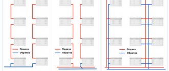
There are two options for arranging the heating of an apartment building:
A feature of the first option is that the project is done without taking into account the personal wishes of the residents of individual apartments.
For example, if in one separate apartment they decide to install a "warm floor" system, and the inlet temperature of the coolant is 70-90 degrees at an allowable temperature for pipes up to 60 ᵒС.
Or, conversely, when deciding to have warm floors for the whole house, one individual subject may end up in a cold apartment if he installs ordinary batteries.
The calculation of the water consumption in the heating system follows the same principle as for a private house.
By the way: arrangement, operation and maintenance of a common boiler room is 15-20% cheaper than an individual counterpart.
Among the advantages of individual heating in your apartment, you need to highlight the moment when you can mount the type of heating system that you consider priority for yourself.
When calculating the water consumption, add 10% for thermal energy, which will be directed to heating staircases and other engineering structures.
The preliminary preparation of water for the future heating system is of great importance. It depends on it how efficiently the heat exchange will take place. Of course, distillation would be ideal, but we do not live in an ideal world.
Although, many today use distilled water for heating. Read about this in the article.
note
In fact, the indicator of water hardness should be 7-10 mg-eq / 1l. If this indicator is higher, it means that water softening in the heating system is required. Otherwise, the process of precipitation of magnesium and calcium salts in the form of scale occurs, which will lead to rapid wear of the system components.
The most affordable way to soften water is boiling, but, of course, this is not a panacea and does not completely solve the problem.
You can use magnetic softeners. This is a fairly affordable and democratic approach, but it works when heated to no higher than 70 degrees.
There is a principle of water softening, so-called inhibitor filters, based on several reagents.Their task is to purify water from lime, soda ash, sodium hydroxide.
I would like to believe that this information was useful to you. We would be grateful if you click the social media buttons.
Correct calculations and have a nice day!
Option 3
We are left with the last option, during which we will consider the situation when there is no thermal energy meter on the house. The calculation, as in the previous cases, will be carried out in two categories (heat energy consumption for an apartment and ODN).
Derivation of the amount for heating, we will carry out using formulas No. 1 and No. 2 (rules on the procedure for calculating heat energy, taking into account the readings of individual metering devices or in accordance with the established standards for residential premises in gcal).
Calculation 1
- 1.3 gcal - individual meter readings;
- 1 400 RUB - the approved tariff.
- 0.025 gcal - standard indicator of heat consumption per 1 m? living space;
- 70 m? - the total area of the apartment;
- 1 400 RUB - the approved tariff.
As in the second option, the payment will depend on whether your home is equipped with an individual heat meter. Now it is necessary to find out the amount of heat energy that was consumed for general house needs, and this must be done according to the formula No. 15 (the volume of services for the ONE) and No. 10 (the amount for heating).
Calculation 2
Formula No. 15: 0.025 x 150 x 70/7000 = 0.0375 gcal, where:
- 0.025 gcal - standard indicator of heat consumption per 1 m? living space;
- 100 m? - the sum of the area of the premises intended for general house needs;
- 70 m? - the total area of the apartment;
- 7,000 m? - total area (all residential and non-residential premises).
- 0.0375 - heat volume (ODN);
- 1400 RUB - the approved tariff.

As a result of the calculations, we found out that the full payment for heating will be:
- 1820 + 52.5 = 1872.5 rubles. - with an individual counter.
- 2450 + 52.5 = 2 502.5 rubles. - without an individual counter.
In the above calculations of payments for heating, data were used on the footage of an apartment, house, as well as on meter readings, which may differ significantly from those that you have. All you need to do is plug your values into the formula and make the final calculation.
Calculation of water consumption for heating - Heating system
»Heating calculations
The heating design includes a boiler, a connection system, air supply, thermostats, manifolds, fasteners, an expansion tank, batteries, pressure-increasing pumps, pipes.
Any factor is definitely important. Therefore, the choice of installation parts must be done correctly. On the open tab, we will try to help you choose the necessary installation parts for your apartment.
The heating installation of the mansion includes important devices.
Page 1
The estimated flow rate of network water, kg / h, to determine the diameters of pipes in water heating networks with high-quality regulation of heat supply should be determined separately for heating, ventilation and hot water supply according to the formulas:
for heating
(40)
maximum
(41)
in closed heating systems
average hourly, with a parallel circuit for connecting water heaters
(42)
maximum, with a parallel circuit for connecting water heaters
(43)
average hourly, with two-stage connection schemes for water heaters
(44)
maximum, with two-stage connection schemes for water heaters
(45)
Important
In formulas (38 - 45), the calculated heat fluxes are given in W, the heat capacity c is taken equal. These formulas are calculated in stages for temperatures.
The total estimated consumption of network water, kg / h, in two-pipe heating networks in open and closed heat supply systems with high-quality regulation of heat supply should be determined by the formula:
(46)
Coefficient k3, taking into account the share of the average hourly water consumption for hot water supply when regulating the heating load, should be taken according to table No. 2.
Table 2. Coefficient values
r-Radius of a circle equal to half the diameter, m
Q-flow rate of water m 3 / s
D-Internal pipe diameter, m
V-speed of the coolant flow, m / s
Resistance to the movement of the coolant.
Any coolant moving inside the pipe strives to stop its movement. The force that is applied to stop the movement of the coolant is the resistance force.
This resistance is called pressure loss. That is, the moving heat carrier through a pipe of a certain length loses pressure.
The head is measured in meters or in pressures (Pa). For convenience, it is necessary to use meters in the calculations.
Sorry, but I'm used to specifying head loss in meters. 10 meters of water column create 0.1 MPa.
In order to better understand the meaning of this material, I recommend following the solution of the problem.
Objective 1.
In a pipe with an inner diameter of 12 mm, water flows at a speed of 1 m / s. Find the expense.
Decision:
You must use the above formulas:
Calculating the volume of water in the heating system with an online calculator
Each heating system has a number of significant characteristics - nominal thermal power, fuel consumption and the volume of the coolant. Calculation of the volume of water in the heating system requires an integrated and scrupulous approach. So, you can find out which boiler, what power to choose, determine the volume of the expansion tank and the required amount of liquid to fill the system.
A significant part of the liquid is located in pipelines, which occupy the largest part in the heat supply scheme.
Therefore, to calculate the volume of water, you need to know the characteristics of the pipes, and the most important of them is the diameter, which determines the capacity of the liquid in the line.
If the calculations are made incorrectly, then the system will not work efficiently, the room will not warm up at the proper level. An online calculator will help to make the correct calculation of volumes for the heating system.
Heating system liquid volume calculator
Pipes of various diameters can be used in the heating system, especially in collector circuits. Therefore, the volume of liquid is calculated using the following formula:
The volume of water in the heating system can also be calculated as the sum of its components:
Taken together, these data allow you to calculate most of the volume of the heating system. However, in addition to pipes, there are other components in the heating system. To calculate the volume of the heating system, including all important components of the heating supply, use our online calculator for the volume of the heating system.
Advice
Calculating with a calculator is very easy. It is necessary to enter in the table some parameters regarding the type of radiators, the diameter and length of the pipes, the volume of water in the collector, etc. Then you need to click on the "Calculate" button and the program will give you the exact volume of your heating system.
You can check the calculator using the above formulas.
An example of calculating the volume of water in the heating system:
The values of the volumes of various components
Radiator water volume:
- aluminum radiator - 1 section - 0.450 liters
- bimetallic radiator - 1 section - 0.250 liters
- new cast iron battery 1 section - 1,000 liters
- old cast iron battery 1 section - 1,700 liters.
The volume of water in 1 running meter of the pipe:
- ø15 (G ½ ") - 0.177 liters
- ø20 (G ¾ ") - 0.310 liters
- ø25 (G 1.0 ″) - 0.490 liters
- ø32 (G 1¼ ") - 0.800 liters
- ø15 (G 1½ ") - 1.250 liters
- ø15 (G 2.0 ″) - 1.960 liters.
To calculate the entire volume of liquid in the heating system, you also need to add the volume of the coolant in the boiler. These data are indicated in the accompanying passport of the device, or take approximate parameters:
- floor boiler - 40 liters of water;
- wall-mounted boiler - 3 liters of water.
The choice of a boiler directly depends on the volume of liquid in the heat supply system of the room.
The main types of coolants
There are four main types of fluid used to fill heating systems:
In conclusion, it should be said that if the heating system is being modernized, pipes or batteries are installed, then it is necessary to recalculate its total volume, according to the new characteristics of all elements of the system.
Heat carrier in the heating system: calculation of volume, flow rate, injection and more
In order to have an idea of the correct heating of an individual house, you should delve into the basic concepts. Consider the processes of circulation of the coolant in heating systems. You will learn how to properly organize the circulation of the coolant in the system. It is recommended to watch the explanatory video below for a deeper and more thoughtful presentation of the subject of study.
Calculation of the coolant in the heating system ↑
The volume of the coolant in heating systems requires an accurate calculation.
The calculation of the required volume of coolant in the heating system is most often done at the time of replacement or reconstruction of the entire system. The simplest method would be to banal use of the appropriate calculation tables. They are easy to find in thematic reference books. According to the basic information, it contains:
- in the section of the aluminum radiator (battery) 0.45 l of the coolant;
- in the section of the cast-iron radiator 1 / 1.75 liters;
- running meter of 15 mm / 32 mm pipe 0.177 / 0.8 liters.
Calculations are also required when installing the so-called make-up pumps and an expansion tank. In this case, in order to determine the total volume of the entire system, it is necessary to add up the total volume of heating devices (batteries, radiators), as well as the boiler and pipelines. The calculation formula is as follows:
V = (VS x E) / d, where d is an indicator of the efficiency of the installed expansion tank; E represents the coefficient of expansion of the liquid (expressed as a percentage), VS is equal to the volume of the system, which includes all the elements: heat exchangers, boiler, pipes, also radiators; V is the volume of the expansion tank.
Regarding the coefficient of expansion of the liquid. This indicator can be in two values, depending on the type of system. If the heat carrier is water, for the calculation its value is 4%. In the case of ethylene glycol, for example, the expansion coefficient is taken as 4.4%.
There is another, rather common, albeit less accurate, option for assessing the volume of the coolant in the system. This is the way in which power indicators are used - for an approximate calculation, you only need to know the power of the heating system. It is assumed that 1 kW = 15 liters of liquid.
An in-depth assessment of the volume of heating devices, including the boiler and pipelines, is not required. Let's consider this with a specific example. For example, the heating capacity of a particular house was 75 kW.
In this case, the total volume of the system is deduced by the formula: VS = 75 x 15 and will be equal to 1125 liters.
It should also be borne in mind that the use of various kinds of additional elements of the heating system (be it pipes or radiators) somehow reduces the total volume of the system.Comprehensive information on this issue is found in the corresponding technical documentation of the manufacturer of certain elements.
Useful video: circulation of coolant in heating systems ↑
Heating agent injection into the heating system ↑
Having decided on the indicators of the volume of the system, the main thing should be understood: how the coolant is pumped into the closed-type heating system.
There are two options:
In the process of pumping, you should follow the readings of the pressure gauge, not forgetting that the air vents on the heating radiators (batteries) must be open without fail.
Heating agent flow rate in the heating system ↑
The flow rate in the heat carrier system means the mass quantity of the heat carrier (kg / s) intended to supply the required amount of heat to the heated room.
Calculation of the heat carrier in the heating system is determined as the quotient of dividing the calculated heat demand (W) of the room (s) by the heat transfer of 1 kg of heat carrier for heating (J / kg).
The flow rate of the heating medium in the system during the heating season in vertical central heating systems changes, since they are regulated (this is especially true for the gravitational circulation of the heating medium. In practice, in calculations, the flow rate of the heating medium is usually measured in kg / h.
Calculation of the heat output of radiators
Heating batteries are used as devices that heat the air space in the rooms. They are made up of several sections. Their number depends on the selected material and is determined based on the power of one element, measured in watts.
Here are the values for the most popular radiator models:
- cast iron - 110 watts,
- steel - 85 watts,
- aluminum - 175 watts,
- bimetallic - 199 watts.
This value should be divided by 100, as a result of which there will be an area heated by one section of the battery.
Then the required number of sections is determined. Everything is simple here. It is necessary to divide the area of the room where the battery will be installed by the power of one radiator element.
In addition, it is necessary to take into account the amendments:
- for a corner room, it is advisable to expand the required number of sections by 2 or 3,
- if you plan to cover the radiator with a decorative panel, besides this, take care of slightly increasing the size of the battery,
- in the case when the window is equipped with a wide window sill, you need to insert an overflow ventilation grill into it.
Note! A similar calculation method can be used only when the ceiling height in the room is standard - 2.7 meters. In any other situation, additional correction factors must be used.