Characteristics of closed expansion tanks
Sealed metal containers are used, in which there is a supply of coolant in case of temperature compression of the liquid. This is how the problem of airing the pipeline is solved. If the coolant, expanding during heating, creates too much pressure, the hydraulic tank compensates for the difference.
Despite the apparent simplicity of the design, the expansion tanks are different from each other, and different models have different operating parameters. Structurally, the following types of hydraulic tanks are distinguished:
- Reservoirs for pear replacement.
- Tanks with a permanently installed membrane.
- Tanks that do not have a membrane in the design.
In the first case, the pear acts as a membrane. It is into it that air is pumped, which changes the volume of the working chamber with a thermal increase in the volume of liquid in the system. The air pressure in the expansion tank must be such as to squeeze water into the pipes when the temperature in the radiators drops.

Setting the tank pressure in the water supply system
Initially at the time of sale, plumbing tanks have a standard pressure of 1.5 bar in the tank chamber. The instructions for use indicate the permissible range, which is not recommended to go beyond, especially in the direction of increase.
To correctly set the optimal mode for the hydraulic tank, the following recommendations are taken as a basis:
- The air pressure in the expansion vessel is adjusted after the power supply is cut off.
- The valves must be closed. The water is drained, leaving the container empty.
- The air pressure in the expansion tank is recorded using a pressure gauge.
- In case of non-conformity, the air is pumped up or vented until the values set by the manufacturer are reached.
In the production of hydraulic tanks, inert gases are used instead of air in order to exclude the appearance of foci of corrosion. When manually adjusted, the pressure is made 10% lower than the manufacturer requires.
It should be remembered that after turning on the pump, the working chamber of the hydraulic tank will be filled with water, and only then will it reach the consumer. If the air pressure drops, the head is unstable. And when the equipment is operating normally, it is constant and does not change while using the system.
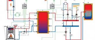
Adjustment of the hydraulic tank in the piping of the water heater
There is one peculiarity here. Such hydraulic tanks should have a slightly higher operating air pressure, namely 0.2 bar higher than what is written in the instructions.
So, if the pump delivers 3.5 bar, the hydraulic tank is set to 3.7 bar. The first functional check and adjustment is performed before starting the system, until the tank is filled with coolant.
No liquid in the chamber is normal operation. And it fills up only when the water in the pipes heats up. Lack of air pressure in the expansion tank leads to the fact that the coolant fills the tank, which is a violation of operational requirements. In this case, it is necessary to turn off and release the system, and then configure the hydraulic tank again.
How to connect an expansion tank
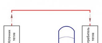
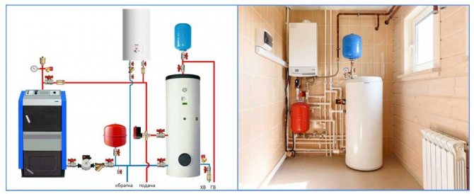
After the tank is securely fixed to the wall or fixed to the floor, it is necessary to correctly connect the expansion tank to the heating pipes. To do this, you need to outline the route for the pipe, passing the shortest path to the point of connection. It is believed that the best connection for closed diaphragm tanks is in the return pipe.Only not just before the entrance to the boiler, but before the circulation pump (if it is not installed in the supply) and the accompanying shut-off valves. Below is a diagram of the expansion tank installation:
There are several justifications for such an inset:
- in the return, the coolant temperature is much lower, which will extend the life of the membrane;
- if the place of installation and tapping is on the return pipeline, then the circulation pump operates in a comfortable mode;
in the supply pipe of a solid fuel boiler, critical pressure and a steam-water mixture can occur due to overheating for various reasons. If this mixture gets into the rubber "bulb" of the container, it will stop performing its functions.
In fact, practice shows that there is no big difference for connection between supply and return. It is simply accepted to connect the expansion tank to the heating system through the return pipe, so it is more reliable. But what definitely does not hurt is a shut-off ball valve on the liner, or even better - a drainage fitting and a second valve. Then at any time the tank can be cut off from the system, drained from it and removed for repair or replacement.
Advice. For those whose gas boiler is not equipped with a pressure gauge or a safety group, it will be useful to build it into the expansion tank circuit using the following installation scheme:
Open type hydraulic tank
Such designs are considered obsolete, since they do not provide absolute autonomy, and can only increase the period between services. The heated liquid evaporates, and its shortage must be eliminated by periodically adding the coolant, replenishing its volume. No diaphragms or pears are used. The pressure in the system appears due to the fact that the open hydraulic tank is mounted on a hill (in the attic, under the ceiling, etc.).
Naturally, there is no air pressure in the open-type expansion tank. When calculating, it is taken into account that one meter of water column creates a pressure of 0.1 atmospheres. However, there is a way to automate the extraction of water. For this, a float is installed, which, when lowered, opens the tap, and after filling the tank it rises and blocks the access of water to the tank. But in this case, you still need to control the operation of the system.
Design features
The purpose of the diaphragm expansion tank is that at all operating stages the device must maintain an equilibrium between the pressure of both parts and, if necessary, neutralize excessive pressure or regulate its differences in the heating structure. Thus, the installation of a diaphragm expansion vessel prevents the occurrence of increased loads in the heating circuit and in emergency situations in the event of malfunctions.
The device comes with a replaceable or non-replaceable membrane. In the first case, the coolant is completely in the flexible membrane tank and cannot interact with the steel inner surface. All work related to the dismantling and subsequent installation of a new product is performed through a bolted flange.
If you purchased a fixed-diaphragm device, it has a two-piece internal cavity. In this case, a non-replaceable diaphragm membrane is used, which is rigidly fixed.
A membrane tank is selected for the heating system directly under a specific heating structure, taking into account the amount of heat carrier. If the volume of the device turns out to be insufficient, then the consequences can be the most negative - cracks often appear and water leakage through the thread is possible. In addition, the pressure in the system often drops below the permissible norm, as a result of which air enters the tank.Therefore, the choice of the device must correspond to the required design parameters (in more detail: "Making the selection of an expansion tank for heating").
An expansion membrane tank for heating systems is used to create a closed-type coolant circulation in order to compensate for its thermal expansion as a result of an increase or decrease in the temperature of the liquid, thereby preventing hydraulic shocks. In continuous mode, both chambers of the device - water and gas - have the same pressure, which makes it possible to maintain the tightness of the system. Such a device for the expansion tank of the heating system has been proven by time and is recognized as the most practical.
The water circulating along the circuit does not contain aggressive gases and therefore corrosion will not render the tank unusable, which allows it to be operated for a long time. The pressure expansion device is placed in the boiler room, and for this reason there is no need to protect it from freezing.
Despite the fact that the selection of a tank for a heating structure is individual, one should not forget that:
- the initial pressure in the membrane heating tank connected to the cold water supply must exceed the static pressure in the system by 30-50 kPa;
- the device needs a spare amount of coolant to compensate for possible leaks.
To protect the closed-loop system with an expansion vessel from too high pressure, safety valves are installed.
Hydraulic tank maintenance rules
The essence of the audit is to check the pressure in the air chamber. The pressure gauge must be in good working order and have a measurement accuracy of 0.1 bar. You can use a car tire pressure tester. Convenient when the scale contains gradation and in atmospheres. Then you do not have to recalculate if the instructions indicate the pressure in other units.
If, as a result of inflation, the air pressure in the expansion tank does not rise, this may indicate that the bulb or membrane has failed and requires replacement. During the inspection, the nipple and valves are checked. They must be sealed.
It is important that this equipment adheres to the parameters set by the manufacturer. It is not worth checking the strength, but after pumping the air should remain in the gas chamber for a long time.
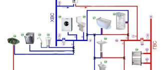
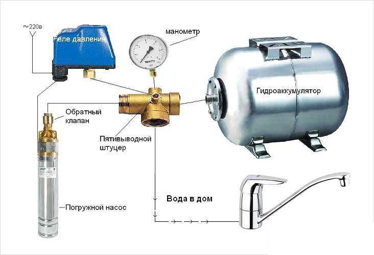
An autonomous water supply system that independently supplies water to parsing points like in a city apartment has long ceased to be a wonder. This is the norm of suburban life, which just needs to be correctly designed, assembled and equipped with equipment that can start and stop the system as you use the cranes.
The principle of operation of the expansion tank ↑
If we analyze the principle of operation of a membrane-type expansion tank, then it is as follows: the coolant heated in a closed loop expands when the increase in volume reaches the tank capacity, the membrane expands, thereby reducing the proportion of air space similar to a piston (that is, air is compressed). During this period, the pressure in the expansion tank capacity, and, accordingly, in the entire system increases. When the water temperature decreases, its volume in the heating system decreases. In addition, the pressure also decreases, so the previously received water is pushed back into the system by means of compressed air.
It's important to know! Before installing an expansion tank in your own home, even at the selection stage, you need to make sure that you have a quality certificate, and in some cases a safety certificate. It is in this case that you can be sure that the selected element of the heating system will be reliable and functional.
If there is a slight leakage of liquid, then the pressure in the system and in the expansion tank drops, and the compressed air squeezes out the reserve volume of water, thus replenishing the heating system. The initial stage of operation of a heating system assumes circumstances in which the pressure of the coolant will be to a certain extent greater than the hydrostatic pressure of the system. For this reason, the liquid chamber of the expansion tank receives the coolant in an amount that corresponds to the operating losses. With an increase in the volume of the liquid chamber of the container, the volume decreases and the pressure in the air chamber of the tank increases. Thus, the steady-state pressure is the initial operating pressure of the heating system.
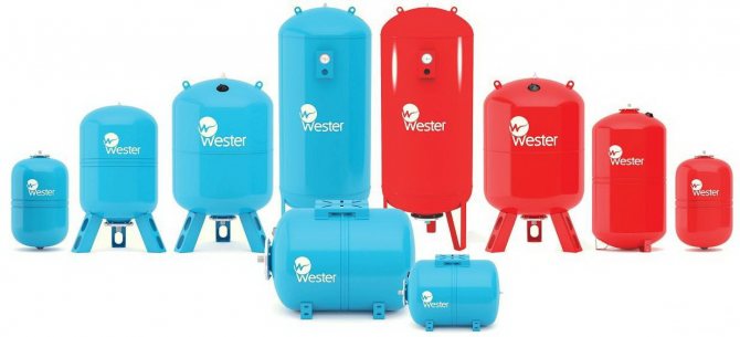
Now you can easily pick up an expansion tank with the required volume
Video: how the hydraulic tank works ↑
Characteristics of closed expansion tanks
A hydraulic tank (or a hydraulic accumulator, an expansion tank) is a metal sealed container that serves to maintain a stable pressure in the water supply system and create water reserves of different volumes.
At first glance, the choice and installation of this device should not cause difficulties - in any online store you can see many models that only slightly differ in shape and volume, but do not differ significantly in their functionality.
It's not like that at all. There are many nuances in the design of the expansion tank and the principle of its operation.
Features of the device and design
Different models of expansion tanks may have restrictions on the way of use - some are designed only to work with industrial water, others can be used for drinking water.
By design, accumulators are distinguished:
- reservoirs with a removable bulb;
- containers with a fixed membrane;
- hydraulic tanks without a membrane.
On one side of the tank with a removable membrane (for a tank with a bottom connection - at the bottom) there is a special threaded flange, to which the pear is attached. On the reverse side there is a nipple for pumping or bleeding air, gas. It is designed to be connected to a regular car pump.
In a tank with a removable bulb, water is pumped into the membrane without touching the metal surface. The diaphragm is replaced by unscrewing the flange held by the bolts. In large containers, to stabilize the filling, the back wall of the membrane is additionally attached to the nipple.
The inner space of the tank with a fixed membrane is divided by it into two compartments. One contains gas (air), the other receives water. The inner surface of such a tank is covered with moisture resistant paint.
There are also hydraulic tanks without a membrane. In them, the compartments for water and air are not separated by anything. Their principle of operation is also based on the mutual pressure of water and air, but with such an open interaction, the two substances are mixed.
The advantage of such devices is the absence of a membrane or a pear, which is the weak link in conventional accumulators.
Diffusion of water and air forces the tanks to be serviced quite often. About once a season you have to pump up air, which gradually mixes with water. A significant decrease in the volume of air, even at normal pressure in the tank, causes the pump to turn on frequently.
The principle of operation of the accumulator
Closed hydraulic tanks for water supply work according to the following scheme: the pump supplies water to the pear, gradually filling it, the membrane increases and the air that is between the pear and the metal body is compressed.
The more water enters the pear, the more it presses on the air, which, in turn, seeks to push it out of the container.As a result, the pressure in the tank rises, this leads to the shutdown of the pump.
For some time, when water is consumed in the system, the compressed air maintains the pressure. It pushes the water into the plumbing. When its amount in the membrane decreases so much that the pressure drops to the lower limit, the relay is activated, again turning on the pump.
Application classification
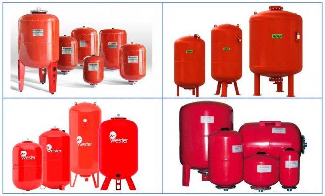
Tanks for water supply and for the heating system should not be confused, therefore, when choosing, you need to find out their purpose. For clear identification, manufacturers paint accumulators for heating in red, for water supply - in blue.
However, some do not adhere to such marking, so the following data can serve as a distinctive feature of devices:
- for water supply, the maximum operating temperature of the accumulator will be up to 70 ° C, the permissible pressure can reach 10 bar;
- devices intended for the heating system can withstand temperatures up to +120 ° C, the working pressure of the expansion vessel is often not higher than 1.5 bar.
All the most important parameters are indicated on the decorative cap (nameplate) that covers the nipple.
The list of functions that the hydraulic tank performs in the cold water system (cold water supply) is much wider:
- Maintaining an even and constant pressure in the water supply. Due to the air pressure, the pressure is maintained for some time even when the pump is off, until it drops to the set minimum and the pump turns on again. Thus, the pressure in the system is maintained even with the simultaneous use of several plumbing fixtures.
- Wear protection of pumping equipment. The supply of water contained in the tank allows for some time to use the water supply without turning on the pump. This reduces the number of pump activations per unit of time and prolongs its operation.
- Water hammer protection. A sharp jump in pressure in the water supply system when the pump is turned on can reach 10 or more atmospheres, which negatively affects all elements of the system. The diaphragm tank takes the impact, equalizing the pressure.
- Creation of water reserves. If the electricity is cut off, the water supply system will give water at least for a short time, but still for some time.
For piping the water heater, expansion tanks are used that can withstand high temperatures.
Materials for hydropneumatic equipment
The expansion tank diaphragm is made of different materials that withstand different temperature ranges during operation.
In accumulators used:
- Natural rubber rubber - NATURAL. The material can come into contact with drinking water and is used for storing cold water. Over time, it may begin to leak water. Withstands temperatures from -10 to 50 ° C above zero.
- Synthetic butyl rubber - BUTYL. The most versatile, waterproof, used for water supply stations, suitable for drinking water. The operating temperature can range from -10 to 100 ° C.
- EPDM synthetic rubber. More permeable than the previous one, it can come into contact with drinking water. The range of permissible temperatures is from -10 to 100 ° C.
- SBR rubber is used only for industrial water. The usage temperature is the same as for the previous brands.
Description, construction types
An expansion tank for water supply is used to maintain the required pressure level with an autonomous water supply. Most often, membrane (expansion tanks) are used for these purposes. These are containers, inside of which there are rubber membranes that divide the volume into chambers. One chamber is water, the other is air.
The tank is connected to the water supply system of the autonomous water supply system of a country house so that the input branch supplies water, filling it, and only after filling a certain volume, water is supplied to consumers.

The principle of operation of the diaphragm expansion tank
The principle of operation is as follows: when the system is turned on (started), the pump pumps water into the water chamber until it is filled. In this case, the volume of the second chamber is significantly reduced.
When the air chamber contracts, the amount of air inside it does not change, so the pressure on the diaphragm increases.
Expansion tanks use a membrane that divides it into 2 tanks, one with air and the other with liquid.
In this case, it is necessary to have pressure control equipment (pressure switch) in the device. This is necessary for automatic shutdown of the pump, the same sensor automatically starts the pump when the pressure in the tank drops below the programmed value. This will allow for the automatic operation of the entire water supply system.
Diaphragm tank installation diagram
For control, it is necessary to install a separate pressure gauge, which will duplicate the relay in case of its breakdown. In this case, it is important to very carefully and accurately adjust the sensor, since the pressure in the water supply depends on its operation. Installation of expansion membrane tanks in an autonomous water supply network solves several issues at once:
- Maintaining pressure when the pump is turned off and in the event of a shutdown for maintenance or repair. In addition, such reservoirs can significantly reduce the power of the water supply pump from the well.
- Protection of the water supply system from water hammer, which can occur due to voltage drops in electrical networks, which significantly increases survivability.
- Protects against pressure drops and other unpleasant nuances associated with the ingress of air into the system (for example, when the level in the well drops).
- In the event of an unexpected shutdown, the pump will maintain some pressure.
- Reduces wear and tear of pumping equipment, thereby extending its service life. This is due to the fact that the pump pumps water only after a decrease in the water pressure, and not after a decrease in the water pressure in the system.
- In the case of low water consumption, it allows not to turn on the pumping equipment at all, but to use only the water that is in the tank.
Characteristics of closed expansion tanks
Expansion tanks are cylindrical or spherical tanks with a horizontal or vertical arrangement of the working chamber. They can be floor-standing or suspended.
The equipment is designed to ensure the uninterrupted operation of the water supply systems of a residential building connected to the central network. Hydraulic accumulators are designed to work in the structure of a water supply system that supplies a resource from underground sources (wells, wells). They are supplied in a set of pumping stations, they have the same purpose, but different requirements and operating conditions.
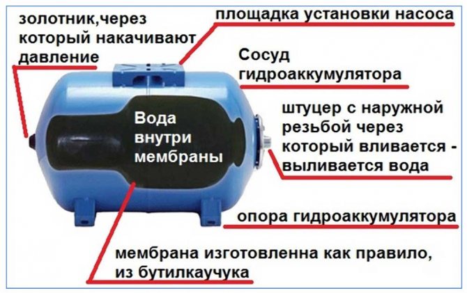
Features of the device and design
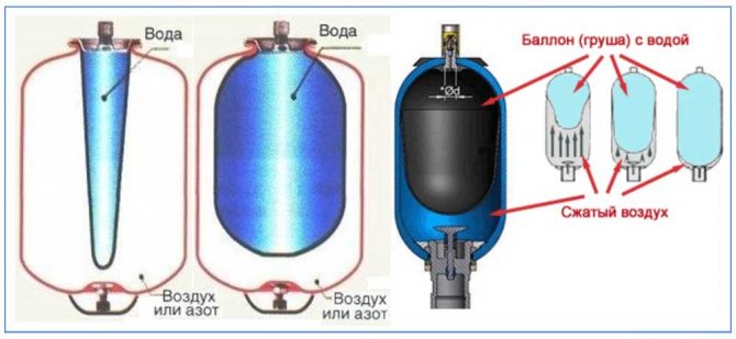
The expansion tank is an impermeable container made of high-alloy steel. The space of the working chamber of the device is divided into two parts by a rubber membrane, which can be of two types in its shape and method of attachment.
In the first version, it is a vertically installed valve, on one side of which there is air, and on the other - water. The second modification of the device is made in the form of a solid pear-shaped container made of rubber, which at the bottom, through the outlet valve, is fixed to the body of the device. There is liquid inside the membrane and air outside.
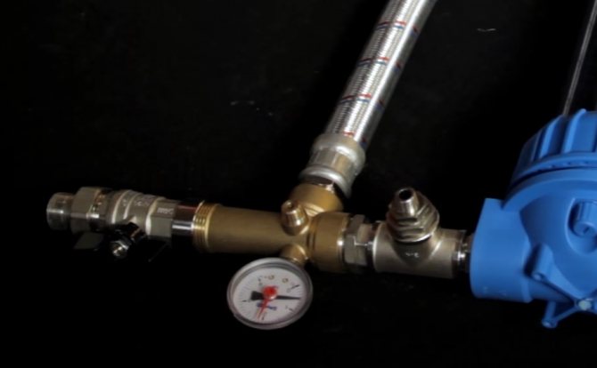
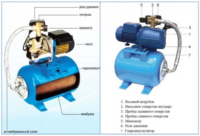
Tanks for domestic use are supplied to the retail network in sizes from 8 to 150 liters. Models from 50 liters are supplied with support stands, a connection for connecting additional devices and a pressure gauge for measuring pressure.
The principle of operation of the accumulator
The principle of operation of the accumulator.
The accumulator is a steel tank with metal supports. There are two chambers inside the body - air and hydraulic. The top of the air chamber is equipped with a nipple through which air can be vented or pumped. The bottom of the tank ends with a special fitting for connection to the water supply.
The principle of operation of the membrane mechanism is as follows: after starting the pumping station, water is supplied to the tank of the device until the density in the system exceeds the maximum allowable level, after which the relay turns off the accumulator. When the taps are opened, the volume of water in the chamber decreases, the pressure drops, the machine switches on the pump, and the pressure stabilizes.
Application classification
Expansion tanks, in terms of their appearance and manufacturing method, are divided into open and closed structures. Open type equipment is a storage tank that is used in country houses with limited water supply. The size and material of the tank are selected taking into account the required volume of water per day. Chambers of this type are used as additional equipment for heating residential buildings.
Closed-type devices are used to compensate for thermal expansions and stabilize pressure. on the following systems:
- cold water supply;
- hot water supply;
- heating;
- water treatment.
Materials for hydropneumatic equipment
The trouble-free operation of any hydropneumatic unit depends on the correct selection of the diaphragm. Depending on the field of application and operating conditions, the part can be made of the following materials:
- Natural rubber - intended for devices with an operating temperature range of -5 ... + 50 ° С.
- Butyl rubber diaphragm - works within 0… + 120 ° С.
- EPDM is a synthetic elastomer, it is operated in the mode + 1 ... + 110 ° С, the working head of the liquid is up to 12 bar.
- SBR diffuser made of styrene-butadiene rubber for hot and cold water supply - up to 15 bar, + 1 ... + 100 ° С.
Calculation of the volume of the tank before selection
In order to properly set up the water supply system of the apartment, you must not be mistaken in choosing the volume of the expansion tank. The method for calculating the size of the container is based on collecting information about household appliances located in the apartment.
Calculation of the volume of the tank before selection.
We draw up a list of connection points indicating the number of each type of equipment, the frequency of switching on per day and determine the total water consumption coefficient (Cy). For example, there are two washbasins, the total frequency of use is 6 times / day: 2x6 = 12. Such calculations must be made with each item. Then add up all the values. The resulting amount will be an indicator of resource consumption in the apartment.
After that, you need to use the table from the international method for calculating UNI 9182, substitute the total coefficient and select the tank of the required size.
Based on the experience of using the calculation system, the volume of capacity for an apartment is:
- up to 3 consumers - expansion tank up to 24 l;
- up to 8 points - 50 l;
- over 10 devices - 100 liters.
Hydraulic tanks connection diagrams
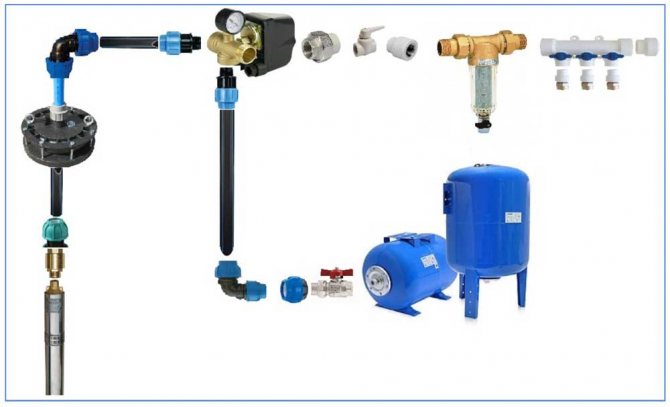
In order to connect hydropneumatic tanks to a cold or hot water supply, they must be equipped with:
Hydraulic tank connection diagram.
- supply, drain and discharge branch pipes;
- pressure gauge;
- safety valve;
- level sensor;
- nipple - a device for regulating and replenishing air.
Expansion tanks for cold water are installed at the lowest point of the distribution system. Hot water supply tanks are mounted on the pipeline route from the side of the liquid supply to the heating equipment (heat exchanger, boiler, etc.).
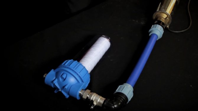
Installation and connection
The expansion tank connection diagram is simple. To do this, the storage device has an inlet and outlet pipes to which the water supply system must be connected. The point of installation of the tank depends on the laying of communications and the availability of free space. It is also recommended to connect the expansion membrane tank with an additional storage tank, which should have a larger volume.
In this case, during installation, it must be remembered that the expansion tank must be installed before connecting the membrane one (i.e., first the storage tank is filled, then the membrane expansion tank). It is recommended to install the storage tank above the diaphragm tank. This will significantly increase the water supply and supply it for a longer time.
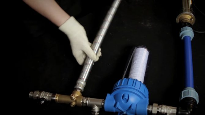
Performing the expansion tank installation
The unit is installed in a room with a temperature of at least 0 ° C. The minimum distance from walls and floor slabs is no more than 60 cm. Around the installed equipment, it is necessary to provide a passage for access to the air valve, drain valve, shut-off valves. The weight of the connected equipment and pipelines is not allowed to influence the device case.
Before installing the hydraulic tank in the chamber, it is necessary to measure the air density with a pressure gauge; it must correspond to the technical characteristics of the mechanism. Fine adjustments can be made through the nipple at the top of the tank. The installation of the device (vertically or horizontally) depends on the volume of the tank and is indicated in the recommendations of the manufacturer when purchasing the equipment.
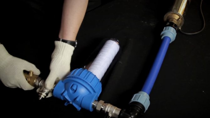
Features of adjusting the accumulator
Setting the operating characteristics of the accumulator is as follows:
- We check the pressure in the air chamber. To do this, we connect the pressure gauge to the rubber valve located at the top of the tank.
- If the obtained values do not correspond to the recommended ones, then by pressing the nipple we bleed the air and reduce the pressure or pump gas to increase the pressure.
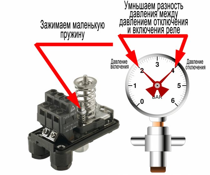
- Then we open the protective cover of the relay and, using a large nut, adjust the upper trigger level, which is responsible for stopping the pump at maximum pressure.
- The lower start limit of the equipment is adjusted with a small fixture.
- We close the relay case and check the results.
Setting the tank pressure in the water supply system
The accumulator is supplied to the retail network with the basic settings of the equipment manufacturer. Sometimes these parameters do not correspond to the operating conditions.
Setting the tank pressure in the water supply system.
The correction of the expansion tank operation is shown in the following situations:
- After installing the unit. Adjustment of values according to the technical regulations of the region.
- Weak head in the system.
- The tank does not fill up.
- Replacing the membrane with a new one.
- Repair of the highway.
- In the air chamber, the recommended values are exceeded, the bases are the readings of the manometer.
- The temperature regime of the hot water supply is violated.
When adjusting the pressure in the gas compartment of the device, it should be taken into account that to protect the container from corrosion, the air chamber is filled with dry nitrogen at the factory. Therefore, when adjusting the air density in the gas cavity or filling the tank after changing the membrane, it is recommended to use technical nitrogen.
The safety valves of the device must be adjusted so that the working pressure in the protected segment does not exceed the standard by more than 10%, and at a set value up to 0.5 MPa ≤ 0.05 MPa.
Adjustment of the hydraulic tank in the piping of the water heater
Expansion tanks for hot water systems compensate for changes in the volume of liquid within the limits of the permissible minimum and maximum temperatures, and also maintain the pressure in the design range.
A diaphragm tank for hot water is installed directly at the point of supply of cold water to the system. Installation of the tank after the pressure reducer is considered optimal. The air concentration in the accumulator chamber must be 0.25 bar higher than the operating pressure in the main line, or 0.2 bar higher than the set pressure at the reducer outlet.
With this setting, excess water, periodically appearing in the system due to an increase in temperature, will gradually be discharged back into the pipeline during the cooling process.
Diaphragm tank for DHW systems
The main difference between membrane tanks for water supply is that the water in them should not come into contact with the walls of the case, as is allowed in heating systems. Therefore, they always use a chamber-type membrane in the form of a rubber bag. In addition, increased requirements for the admissibility of contact with food liquids are imposed on the membrane material of tanks for water supply.
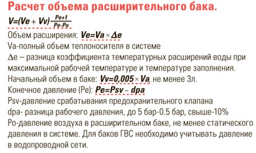
The calculation of the expansion tank for hot water supply is made according to formula 1. The volume of water in the system is calculated taking into account the water contained in the pipelines and the water heater or heat exchanger.
Some water heaters are designed with a damping air cushion in the enclosed volume of the water heater itself. The volume of this cushion is determined by the height of the DHW outlet pipe and must also be taken into account when selecting the DHW expansion tank.
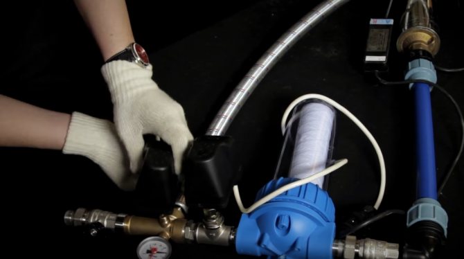
Installation of an expansion tank in a hot water system
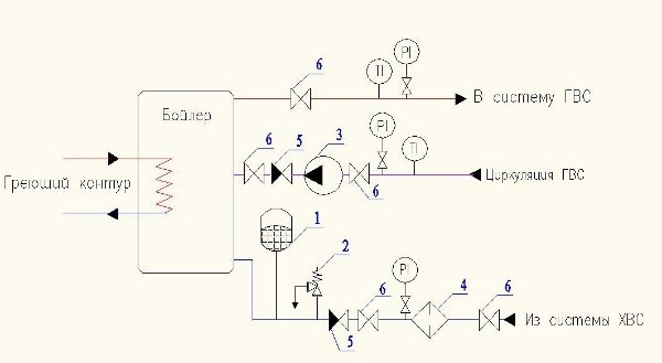
1 - expansion tank; 2 - safety valve; 3 - pump; 4 - filter; 5 - check valve; 6 - shut-off valve.
Hydraulic tank maintenance rules
Hydraulic tank maintenance rules.
Installation, testing and repair of equipment should be carried out in accordance with the recommendations of the manufacturer by specialists who have undergone special training.
Any changes to the expansion chamber design using welding or mechanical stress are prohibited.
Once a year, a preventive inspection of the hydraulic tank is required:
- Check the pressure in the air chamber.
- Carry out an external inspection of the unit body.
- Examine instrumentation (pressure gauge, valves, relays, etc.).
- Inspect the tightness of pipelines and the operation of valves.
Open type hydraulic tank installation
Expansion tanks of an open type are attachments that are mounted at the top of the line. The installation site must be well ventilated to avoid the formation of condensation on the surface of the device. The height of the container should allow free access to the inside of the container for technical inspection or repair of the working chamber.
The reservoir is equipped with a float valve that is installed on the inlet line. It is designed to maintain the liquid level in the storage chamber, which prevents overflow of water over the edge of the tank.
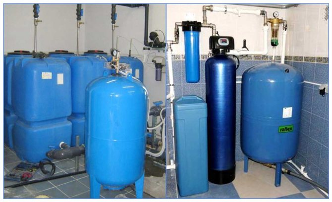
Installation of storage tanks
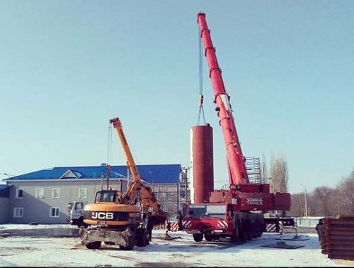
LLC "OZRM" carries out construction and installation of hot water storage tanks (BAGV tanks, hot water supply tanks) with a volume of 100 to 20,000 m3.
Installation of storage tanks hot water for heat supply systems (hot water supply) is carried out in conjunction with the installation of thermal insulation fasteners and the installation of metal structures of bandages (protection against avalanche destruction), which are manufactured according to individual KM projects or according to standard projects (TP) and standard series (TS), provided that they are bound to the construction site.
Installation and installation of storage tanks solves the problem of storing a stock of heated water necessary to equalize the flow of hot water supply in central heating and heating systems.
Operating conditions for storage tanks, which are assembled and built by OZRM LLC:
- Maximum hot water temperature 95 C.
- The design temperature of the outside air is -40 C for black steel st3sp5;
- The design temperature of the outside air is -60 C for black steel 09g2s.
Standard volumes of storage tanks BAGV (m3) which are installed by OZRM LLC: 10, 20, 30, 50, 75, 100, 200, 300, 400, 500, 630, 700, 900, 1000, 1500, 2000, 2500, 3000, 5000, 10000, 15000, 20,000.
Installing the storage tank at the request of the customer, any non-standard volume from 1 to 30,000 m3 is possible.
In the manufacture and installation of hot water tanks metals should be used that have the desired mechanical characteristics, chemical composition, good performance at low temperatures, increased corrosion resistance and the ability to roll sheet blanks.
During the construction of hot water tanks all pipelines are connected to the vertical walls of the tank with the installation of compensating devices to eliminate pressure on the wall when the pipelines connected to the storage tank are lengthened when they are heated.
To prevent avalanche destruction, external reinforcing structures, consisting of horizontal circular belts (bands) and vertical racks, must be installed on the accumulator tanks being installed and put into operation. The distance between the shrouds is set by the project depending on the value of tensile forces and the location of hatches and pipeline inlets.
Installation of external reinforcing structures (bandages) is mandatory in accordance with the Circular Ts-02-98 (T) [24] for accumulator tanks BAGV with a capacity of 400 m3 or more with seismicity up to 6 points, and if the seismicity is 6 points or more, then mandatory installation of tires on BAGV from 100 m3.
Installation of protection against avalanche destruction performed on a tank not filled with water.
Installation of tank bands made from bottom to top, while they are installed strictly horizontally, without distortions.
Anti-corrosion protection (AKZ) the inner surface of the storage tanks are used sealants, cathodic protection, metallized aluminum coating, epoxy compounds, paints and enamels.
Typical designs provide for corrosion protection of the inner surface of the tank with the sealing liquid AG-4, AG-4I, which forms a regenerating anticorrosive lubricant on the inner surface when the water is lowered and raised.
When installing a group of storage tanks or a free-standing tank located on the territory of a heat source (boiler room, CHP, TPP and others) must be protected with a shaft with a height of at least 0.5 m and a width at the top of at least 0.5 m, and a blind area must be made around the tank.
When installing BAGV it is necessary to provide: an overflow pipe at the mark of the maximum permissible filling level; The vestibule pipe, the cross-section of which should ensure the free flow of air into the tank, excluding the formation of vacuum when pumping water from the tank, and the free release of the vapor-air mixture, which prevents an increase in pressure above atmospheric when charging the tank.
When installing the BAGV tank it is necessary to provide:
- automatic level regulators;
- a blocking device that turns off the discharge pumps when the lower limit water level in the storage tank is reached;
- automatic device for switching the power supply system of the tank farm to a reserve source;
- signaling of reaching the upper limit level, the beginning of water overflow through the overflow pipe and switching off the discharge pumps when the lower level is reached;
- drainage line with fittings designed to completely remove residual water during inspections and repairs;
- Instrumentation for measuring the level (recording device), pressure in all supply and outlet pipelines (indicating device), water temperature in the tank (indicating device);
- devices for remote measurement of water level on each tank or group of tanks.
During the construction of storage tanks at facilities with permanent attendants, light and sound alarms are output to the premises of the duty personnel.