Solid fuel boiler plants cannot operate for a long time without the intervention of a person who must periodically load firewood into the furnace. If this is not done, the system will begin to cool down and the temperature in the house will drop. In the event of a power outage when the furnace is completely burnt out, there is a danger of boiling up of the coolant in the jacket of the unit and its subsequent destruction. All these problems can be solved by installing a heat accumulator for heating boilers. It will also be able to perform the function of protecting cast iron installations from cracking at a sharp drop in the temperature of the supply water.
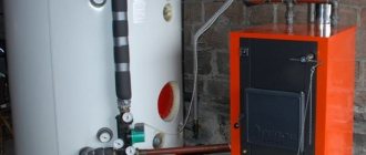
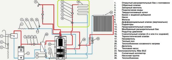
Connecting a solid fuel boiler with a heat accumulator
Calculation of the buffer capacity for the boiler
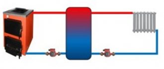
The role of the heat accumulator in the general heating scheme is as follows: during the operation of the boiler in normal mode, accumulate thermal energy, and after the firebox decays, give it to the radiators for a certain period of time. Structurally, the heat accumulator for a solid fuel boiler is an insulated water tank with an estimated capacity. It can be installed both in the combustion room and in a separate room of the house. It makes no sense to put such a tank on the street, since the water in it will cool down much faster than inside the building.

Connecting a heat accumulator to a solid fuel boiler
Given the availability of free space in the house, the calculation of the heat accumulator for a solid fuel boiler in practice is done as follows: the capacity of the tank is taken from the ratio of 25-50 liters of water per 1 kW of power required to heat the house... For a more accurate calculation of the buffer capacity for the boiler, it is assumed that the water in the tank heats up during the operation of the boiler plant to 90 ⁰С, and after turning off the latter, it will give off heat and cool down to 50 ⁰С. For a temperature difference of 40 ° C, the values of the heat given off for different tank volumes are presented in the table.
Table of values of the given heat for different tank volumes
| Heat accumulator volume, m3 | 0.35 | 0.5 | 0.8 | 1 | 1.5 | 2 | 3 | 3.5 |
| The amount of heat given off at a temperature difference of 40 ⁰С, kW / h | 20 | 30 | 45 | 58 | 85 | 115 | 170 | 210 |
Even if there is room for a large capacity in a building, this does not always make sense. It should be remembered that a large amount of water will need to be heated, then the power of the boiler itself should initially be 2 times more than is needed to heat the dwelling. A tank that is too small will not perform its function, since it will not be able to accumulate enough heat.
Calculation of the capacity of the heat accumulator
The calculation methodology can be different depending on the application scheme. Here is a rough calculation chart:
- Determination of the maximum fuel load. For example, the firebox holds 20 kg of firewood. 1 kg of firewood is able to release 3.5 kWh of energy. Thus, when burning one bookmark of firewood, the boiler will give 20 3.5 = 70 kWh of heat. The time it takes for a complete bookmark to burn can be determined empirically or calculated. If the boiler output is, for example, 25 kW 70: 25 = 2.8 h.
- Heat carrier temperature in the heating system. If the system is already installed, it is enough to measure the temperature at the inlet and outlet and determine the heat loss.
- Determination of the desired download frequency. For example, loading is possible in the morning and in the evening, but it is not possible to service the boiler during the day and at night.
Calculation of the heat accumulator
If, for an hour, the heat loss of a room, for example, is 6.7 kW, then per day it will be 160 kW. In this example, this is slightly more than two fuel fillings.As it was defined above, one tab of firewood burns for about 3 hours, releasing 70 kWh of thermal energy.
The need for heating the house is 6.7 3 = 20.1 kWh, the storage tank reserve will be 70-20.1 = 49.9, that is, approximately 50 kWh. This energy will be enough for a period of 50: 6.7 - this is about 7 hours. This means that two full snacks and one incomplete one are required per day.
Based on these calculations, having considered several options, we will stop at this: at 23 o'clock, an incomplete load is made, at 6.00 and 18.00 - full. If you draw a graph of the charge level of the heat accumulator, you can see that the maximum charge falls on 60 kWh at 9 am.
Since 1 kWh = 3600 kJ, the reserve should be 60 3600 = 216000 kJ of thermal energy. The temperature reserve (the difference between the maximum water indicator and the required flow rate) is 95-57 = 38 ° С. Heat capacity of water 4.187 kJ. Thus, 216000 / (4.18738) = 1350 kg. In this case, the required volume of the heat accumulator will be 1.35 m3.
The considered example gives a general idea of how the storage tank capacity is calculated. In each individual case, it is necessary to take into account the peculiarities of the heating system and the conditions of its operation.
Features of installing a heat accumulator
Before installing the equipment, a detailed design must be drawn up. All requirements of the heating equipment manufacturers must be taken into account. When installing the storage tank, the following rules must be observed:
- The surface of the container must have reliable thermal insulation.
- Thermometers should be installed at the inlet and outlet to monitor the temperature of the water.
- Volumetric tanks most often do not fit into the doorway. If it is not possible to bring in the tank before the end of construction, you will have to use a collapsible version or several smaller tanks.
- A coarse filter is desirable on the inlet pipe.
- A safety valve and a pressure gauge should be installed near the tank. There should also be an air vent valve in the tank itself.
- It must be possible to drain the water from the tank.
Advice! Quite often, the presence of a heat accumulator is a prerequisite for a guarantee by the manufacturer of a solid fuel boiler.
The use of a heat accumulator in a system with a solid fuel boiler increases the efficiency of the heat generator and its service life, and also allows more economical fuel consumption. Possibility of less frequent loading of fuel makes the use of the heating boiler more convenient for the consumer. The calculation of the required capacity of the storage tank must take into account the type of boiler, the characteristics of the heating system and the conditions of its operation.
Selection recommendations
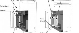
The selection of a heat accumulator for a solid fuel boiler is influenced by the presence of free space in the room. When buying a large storage tank, it will be necessary to provide for a foundation device, since equipment with a significant mass cannot be placed on ordinary floors. If, according to the calculation, a tank with a volume of 1 m3 is required, and there is not enough space for its installation, then you can purchase 2 products of 0.5 m3 each, placing them in different places.
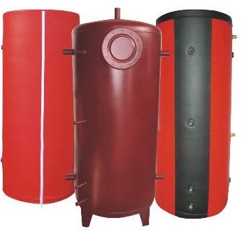
Heat accumulator for solid fuel boiler
Another point is the presence of a DHW system in the house. In the event that the boiler does not have its own water heating circuit, it is possible to purchase a heat accumulator with such a circuit. Of no small importance is the value of the working pressure in the heating system, which traditionally should not exceed 3 bar in residential buildings. In some cases, the pressure reaches 4 bar, if a powerful home-made unit is used as a heat source. Then the heat accumulator for the heating system will have to be chosen in a special design - with a torispherical cover.
Some factory hot water accumulators are equipped with an electric heating element installed in the upper part of the tank. Such a technical solution will not allow the coolant to cool down completely after stopping the boiler, the upper zone of the tank will be heated. Domestic hot water supply will operate.
Simple switching circuit with admixture
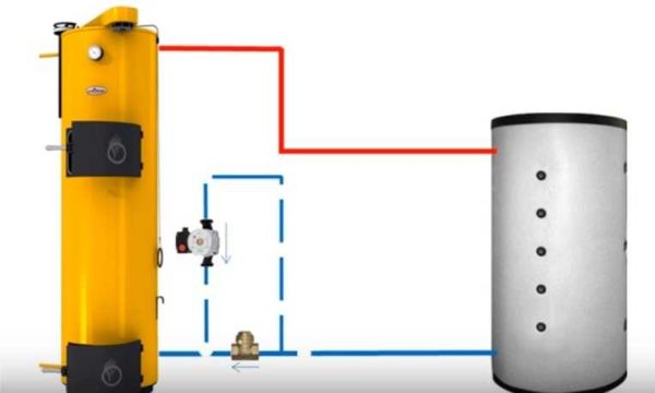
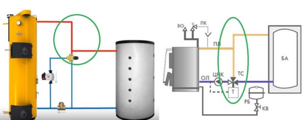
The storage device can be included in the system in different ways. The simplest piping of a solid fuel boiler with a heat accumulator is suitable for working with gravitational coolant supply systems and will operate in the event of a power outage. For this, the tank must be installed above the heating radiators. The circuit includes a circulation pump, a thermostatic three-way valve and a non-return valve. At the start of the heating cycle, water driven by the pump flows through the supply line from the heat source through the three-way valve to the heaters. This continues until the flow temperature reaches a certain value, for example 60 ° C.
Heat accumulator for heating boilers
At this temperature, the valve begins to mix cold water into the system from the lower branch pipe of the tank, observing the set temperature of 60 ⁰С at the outlet. Heated water will begin to flow into the tank through the upper branch pipe, directly connected to the boiler, and the battery will start charging. With complete combustion of wood in the firebox, the temperature in the supply pipe will begin to drop. When it drops below 60 ° C, the thermostat will gradually cut off the supply from the heat source and open the flow of water from the tank. That, in turn, will gradually be filled with cold water from the boiler and at the end of the cycle the three-way valve will return to its original position.
The check valve, connected in parallel with the three-way thermostat, is activated when the circulation pump is stopped. Then the boiler with the heat accumulator will work directly, the coolant will go to the heating devices directly from the tank, which will be replenished with water from the heat source. In this case, the thermostat does not take part in the operation of the circuit.
Where to put the circulation pump
In most piping schemes for a heat accumulator with a circulation pump, it is located in the return pipe in front of the boiler. In the return line - because the temperature is lower here, but you can also put it on the feed. Modern pumps are designed to pump coolant up to 110 ° C, so they feel good there. The second point: when installed on the flow, the pump will not create additional pressure on the heat exchanger, which will extend its service life.
In any case, when installing a circulation pump in the supply or return, there is no possibility of natural circulation. That is, in the event of a power outage, the circulation will stop, the boiler will inevitably boil. To avoid this, a four-way valve is installed, through which superheated water is discharged into the sewer and fed with cold water from the cold water supply. In this way, emergency cooling of the heat exchanger is organized and the boiling of the coolant is prevented.
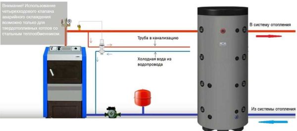
One of the ways to avoid overheating of the coolant in the heating boiler
Please note that this scheme can only be implemented on steel or copper heat exchangers. With cast iron - it is impossible. They may burst if exposed to cold water.
There is another way. It is more gentle in relation to the heat exchanger (suitable for cast iron) and requires less materials. You can make a piping between the boiler and the heat accumulator for heating so as to maintain natural circulation. In this case, when the power supply is cut off, the boiler will not boil - it will continue to heat the water in the container.
To preserve the natural circulation of the coolant, the pump is placed in a separate, specially created circuit. In order for the circuit to work, a large cross-section petal check valve is installed in the circuit.
This way, natural circulation is maintained even in the absence of power supply
When the circulation pump is not working, it passes the heat carrier flow from the TA. When the circulation pump is operating, it props up the valve with its pressure and the coolant flows through the pump. A pipe at least an inch in diameter goes to the pump. Only in this case can natural circulation be preserved.
Hydraulic separation scheme
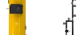
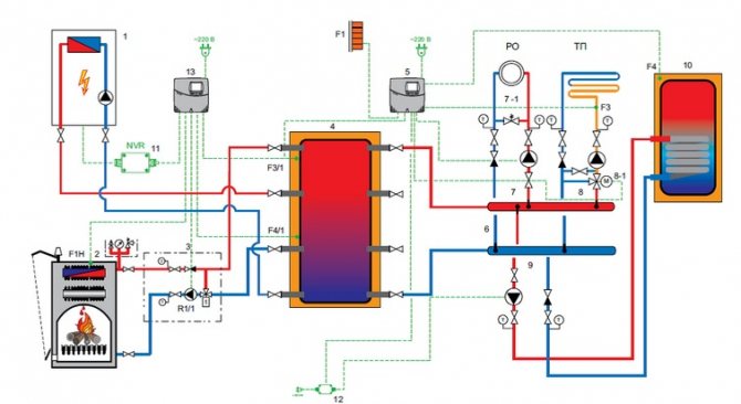
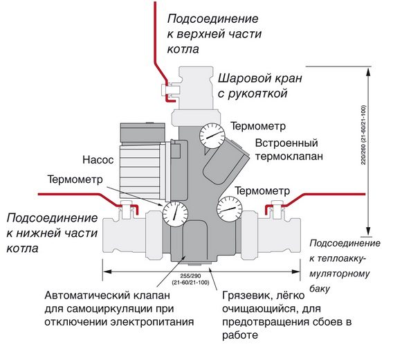
Another, more complex connection scheme, implies an uninterrupted supply of electricity. If this is not possible, then it is necessary to provide for connection to the network through an uninterruptible power supply. Another option is to use diesel or gasoline power plants. In the previous case, the connection of the heat accumulator to the solid fuel boiler was independent, that is, the system could work separately from the tank. In this scheme, the accumulator acts as a buffer tank (hydraulic separator). A special mixing unit (LADDOMAT) is built into the primary circuit through which water circulates when the boiler is fired up.
Connecting a heat accumulator to a solid fuel boiler
Block elements:
- circulation pump;
- three-way thermostatic valve;
- check valve;
- sump;
- Ball Valves;
- temperature control devices.
Differences from the previous scheme - all devices are assembled in one block, and the coolant goes to the tank, and not to the heating system. The principle of operation of the stirring unit remains unchanged. Such a piping of a solid fuel boiler with a heat accumulator allows you to connect as many heating branches as you like at the outlet from the tank. For example, to power radiators and floor or air heating systems. Moreover, each branch has its own circulation pump. All circuits are hydraulically separated, excess heat from the source is accumulated in the tank and used when needed.
Connecting TA to consumers
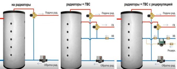
On the other hand, the heat storage tank must be connected to the heating system. If we connect only radiators, everything is simple - from one of the upper outlets a pipe goes into the supply pipeline, and we connect the return pipe to the lower one. But, in this case, the radiators may overheat. When the water in the tank is heated to temperatures above 60 ° C, it can be dangerous, and the temperature can be 90 ° C or even higher. When touching such hot radiators, there is a high probability of getting a serious burn. In addition, it will clearly be hot in the room.
Connecting radiators
To avoid feeding too hot a heat carrier, install another three-way mixing valve. The circuit works the same as described above. We set the required temperature on the regulator, for example, 50 ° C. As soon as the coolant in the supply is hot, the valve will open the water mix from the return line.
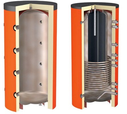
One of the benefits of installing a heat accumulator is the ability to prepare DHW in the same container (middle picture in the figure below). For this, a heat exchanger or container is built into the tank. Its outlet is connected to a hot water supply comb.
Buffer tank piping schemes from the side of the heating system
Since overheating is also possible in this case, a mixing unit is also needed here. You just need to add cold tap water. This unit is implemented using another three-way mixing valve. The outlet from the cold water supply is connected to a three-way DHW mixing valve. So that, in the absence of hot water parsing, it does not fall into the cold water comb, we put a check valve on the supply line from the cold water supply.
This heat accumulator piping scheme has a significant drawback: when hot water is not used, the water in the pipes cools down. To "get" warm, you have to pour the cooled down just into the sewer. This is inconvenient because you have to wait and is uneconomical.To solve the problem, a return line is pulled from the last point of parsing, in which their circulation pump is installed. This circuit is called recirculation. Until the tap is turned on anywhere, the water runs in a circle. Thus, warm water is constantly drawn from all taps. Pay attention to the installation of check valves - they are mandatory for the operation of the circuit.
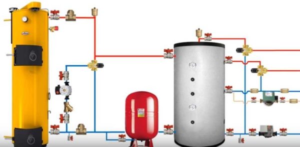
Heat accumulator piping for individual heating with all functional elements and fittings
For the final study of the scheme, it is also necessary to stipulate the place of installation of the fittings. These are automatic air vents that are installed at the highest points of the system. Stopcocks are also needed. They are installed near each large functional unit so that, if necessary, it is possible to turn off the taps and remove the equipment for repair or maintenance.
How to power a warm water floor
A warm floor can be connected to a heat accumulator very well. The piping in this case is no different from the case with radiators. We need the same mixing unit with a three-way mixing valve, but it should be set to a lower temperature - no higher than + 40 ° C. In this case, you can connect an underfloor heating without a mixing unit - the temperature must be controlled when leaving the boiler. But you can play it safe - put a second mixing unit on the underfloor heating distribution manifold.
Heat storage piping with a warm water floor (in a green loop)
There is also a second option for piping a heat accumulator with a warm floor - supply the same temperature as the coolant that goes to the radiators. The mixing unit will lower it. The hassle and costs are less (only tees are needed to branch off from the main line), but the reliability of such a solution is lower. Although, this equipment copes with the coolant supplied by an ordinary boiler.
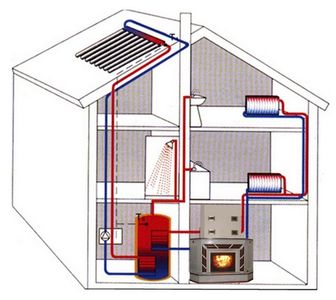
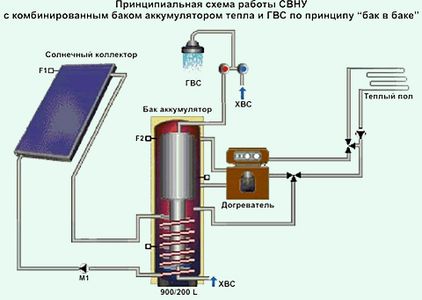
Heat accumulator is a unit for collecting and increasing heat for the purpose of its further use. The device is used in private houses, apartments, at enterprises, as well as for pre-heating engines. The heat accumulator for the heating system allows to reduce energy costs for space heating and hot water supply. The units are installed in the piping of a solid fuel boiler or connected to the solar system.
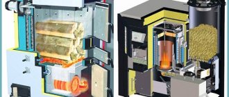
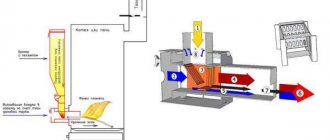
The work of a solid fuel boiler in the heating system is a certain cyclicality. First, fuel is put into it, ignited, and then the boiler gradually reaches its maximum power and transfers thermal energy through the coolant to the heating system.
The firewood bookmark gradually burns out, the heat transfer decreases, and the coolant cools down. During the period of peak power, part of the thermal energy remains unclaimed, and during the afterburning of the fuel, on the contrary, it will not be enough. To repeat the cycle, the solid fuel should be loaded again.
Advantages and disadvantages
A heating system with a heat accumulator, in which a solid fuel plant serves as a heat source, has a lot of advantages:
- Improving the comfort conditions in the house, since after the fuel has burned out, the heating system continues to heat the house with hot water from the tank. There is no need to get up in the middle of the night and load a portion of firewood into the firebox.
- The presence of a container protects the boiler water jacket from boiling and destruction. If the electricity is suddenly cut off or the thermostatic heads installed on the radiators cut off the coolant due to reaching the desired temperature, then the heat source will heat the water in the tank. During this time, the electricity supply may resume or the diesel generator will be started.
- The supply of cold water from the return pipeline to the red-hot cast-iron heat exchanger after a sudden start of the circulation pump is excluded.
- Heat accumulators can be used as hydraulic dividers in the heating system (hydraulic arrows). This makes the operation of all branches of the circuit independent, which gives additional savings in thermal energy.
The higher cost of installing the entire system and the requirements for the placement of equipment are the only disadvantages of using storage tanks. However, these investments and inconveniences will be followed by minimal operating costs in the long term.
Solving the condensation problem
A logical solution to the problem of too cold water on the return is to add hot water from the supply. This is done using a jumper and an adjustable three-way mixing valve installed on the branch. The valve must be of a mixing type: when the set temperature is reached, it smoothly begins to move the valves in the two connected pipes. Thus, a gradual and smooth temperature change is obtained.
Heat accumulator piping: additional circuit for mixing warm water into the return
Cold water in the return pipe appears in several cases: during the acceleration of the boiler, when the water in the heat accumulator has cooled down strongly (after idle time), and the boiler is in operation. Let's take a look at how this heat accumulator connection scheme works in both cases. The movement of the coolant is shown in the illustrations below.
Until the boiler has warmed up, the coolant is completely cold. In this case, the three-way valve shuts off the coolant flow to the TA and it moves in a small circle (picture below, top left picture). Warming up occurs quickly, since there is little water, the time for the formation of condensation is minimal. The figure assumes that the 3-way valve is set to 55 ° C. Until the water in the small circle reaches this temperature, it circulates in it.
When the coolant in the small ring heats up to 55 ° C, the valve shifts the flaps, the heat accumulator for heating is switched on. In this case, three streams go simultaneously (the right figure in the top row):
- small, as in the first picture;
- part of the coolant goes to the TA through the valve;
- from the TA along the return line, through the valve, to the pump and to the boiler heat exchanger (third circle).