The inability to connect to the gas main pipeline pushes the consumer to use electric and solid fuel (TT) heat generators. Despite the many advantages, both electrical and solid fuel boiler plants are not without drawbacks. In the first case, it is the high cost of electricity.
When obtaining energy from solid fuel, the main negative factor will be the need to constantly monitor the amount of fuel in the combustion chamber. This problem can be partially solved by connecting the heat accumulator to a solid fuel boiler. The purpose and application of this device in the heating system (CO) will be discussed in this publication.
[contents]
How to properly tie a solid fuel boiler
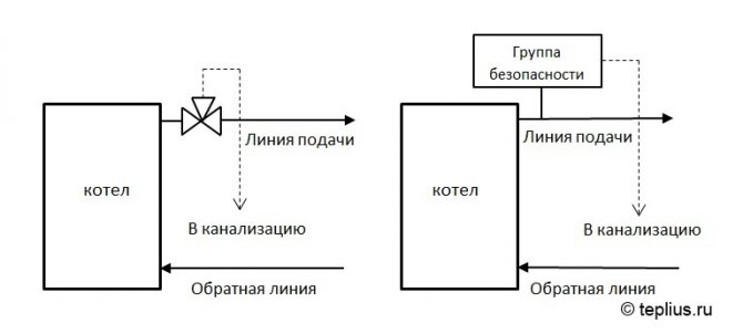
The piping of a solid fuel boiler requires the provision of certain safety measures for the heating system:
- installation of an emergency valve (or boiler safety group). In the event of a rise in pressure in the heating system, an emergency discharge of the coolant into the sewer will occur. And this will prevent the boiler from exploding.
- installing a cooling circuit on a solid fuel boiler will save you from a boiler explosion, as well as from the need to recharge the heating system in the case described above.
- connecting an uninterruptible power supply UPS to the boiler and pumps will allow the heating system to work properly even in the event of a power outage, which we often hear about in the news in many settlements of Belarus.
- the connection of a solid fuel boiler according to fire regulations must be made only with a metal pipe (ferrous metal, galvanized, stainless or carbon steel), any option will do. As for the diameters, we most often connect boilers up to 30 kW with a 1 1/4 ″ pipe, boilers up to 50 kW - 1 1/2 ″, and boilers up to 100 kW - 2 ″ or 2 1/2 ″.
- in the connection diagram of a solid fuel boiler and, accordingly, when tying a solid fuel boiler, it is necessary to provide an open or closed expansion tank (depending on the heating system). The volume of the expansion tank is calculated using a simple formula:
V tank = V system: 10The solid fuel boiler connection diagram requires the installation of an expansion tank on the return line. This will prolong the life of the tank membrane.
- connect a solid fuel boiler (up to 70-80 kW), preferably not using welding, but on threaded connections. In the future, this will simplify the maintenance of the entire system, and will also allow replacing any failed unit without any problems.
- the connection diagram for a solid fuel boiler implies the presence of a thermostatic mixing valve (for steel boilers it is protection against excessive condensate, and for cast iron - protection against a cold return flow, under the influence of which the boiler section can burst).
These are just some of the nuances that must be paid close attention to when connecting a solid fuel boiler. The safety of a home heating system is the first thing that begins with heating design.
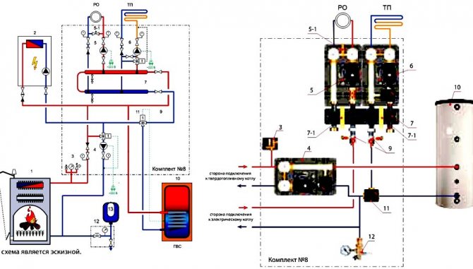
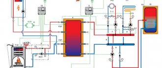
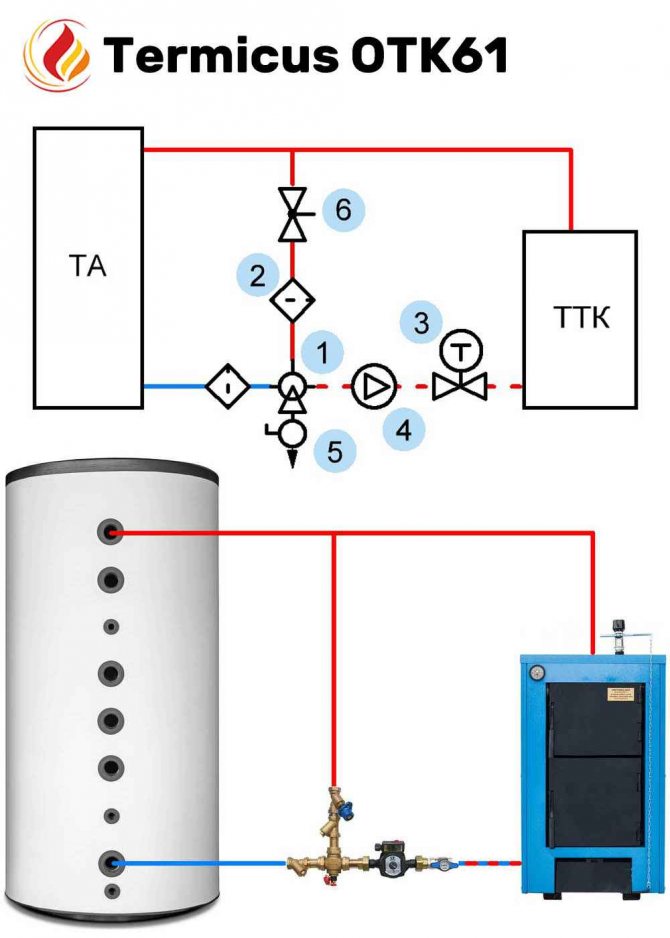
Standard connection schemes
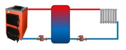
The correct choice of the connection diagram for the heat tank-accumulator depends on many factors.
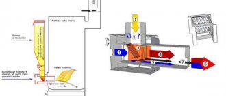
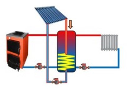
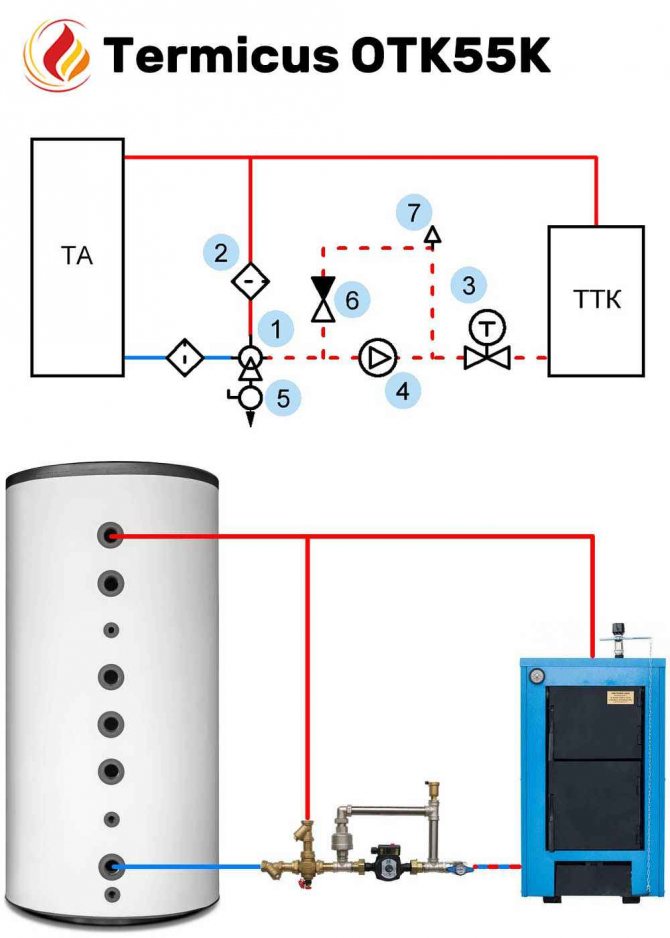
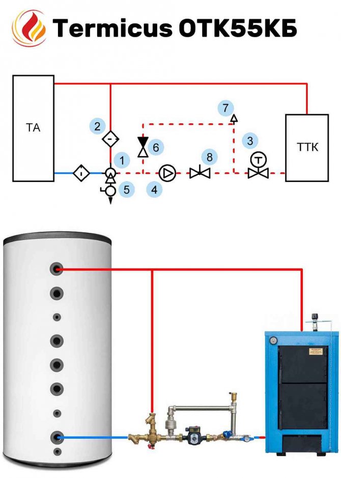
This scheme is used at the same temperature and pressure of CO water both in the boiler and in the heating circuit.
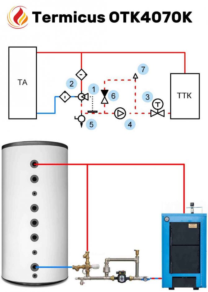
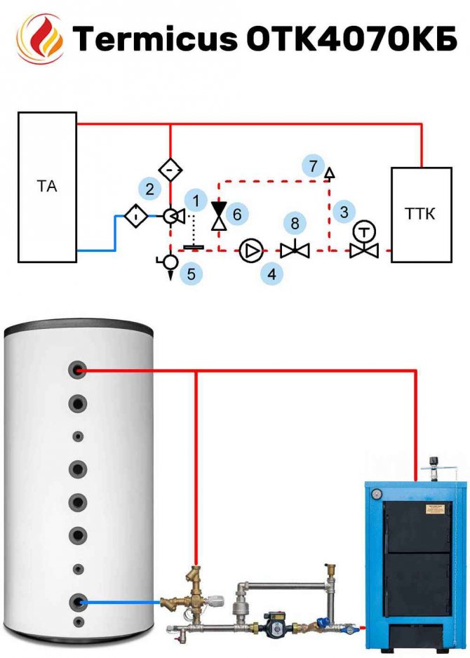
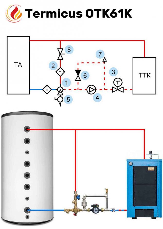
The second figure shows a more rational scheme for switching on a heat accumulator with regulation of the temperature of the coolant through the use of mixing thermostatic valves.
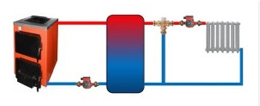
This scheme is used if a different coolant is used in the heating and boiler circuits. There is also a second application option: when the pressure in the boiler circuit exceeds the permissible pressure in the heat storage tank.
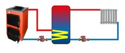
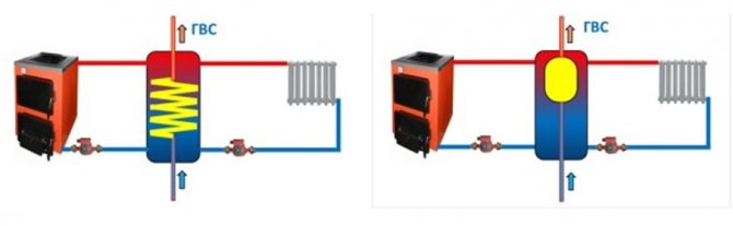
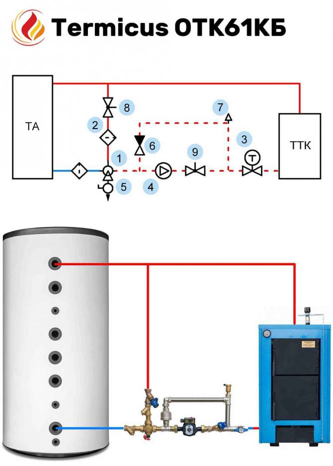
The schemes shown above are applicable when organizing hot water supply, through a flow-through heat exchanger or a tank integrated into a heat accumulator.
The scheme is designed in the presence of two boiler plants, one of which can be a solar water heater.
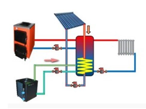
Connection diagram in the presence of three heat generators.
Advice: despite the apparent simplicity, the piping scheme for a solid fuel heating boiler with a heat accumulator requires careful analysis and design with a large number of complex heat engineering calculations, which should be trusted exclusively by professionals.
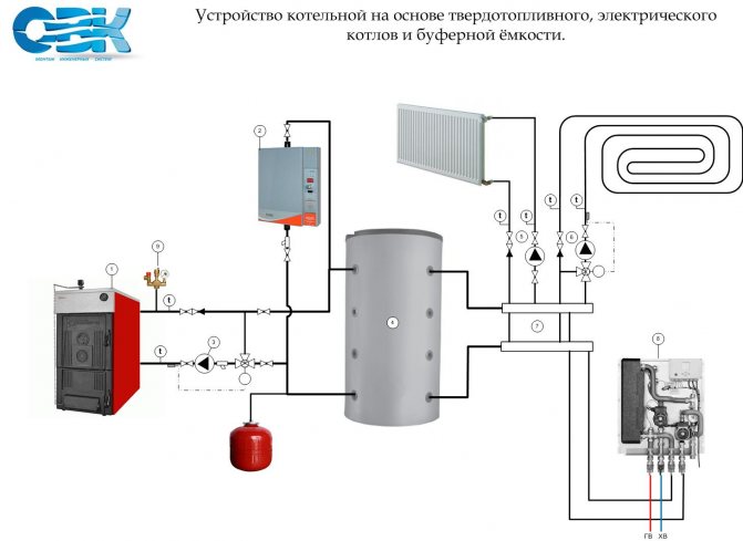
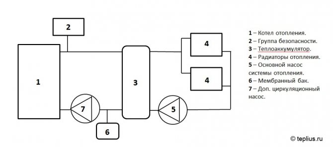
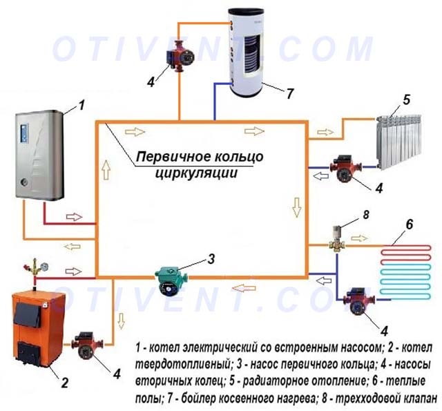
Boiler connection diagrams for general presentation
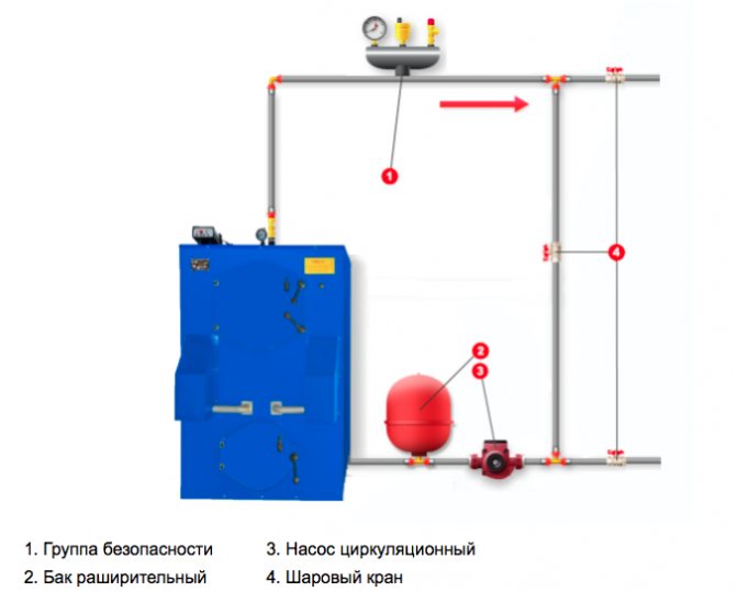
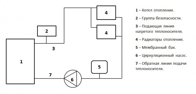
Let's analyze the harness in the diagrams. Simple boiler piping includes:
- circulation pump (1) to ensure the movement of the heat carrier (water) in the pipes and equipment of the heating system,
- the expansion tank (2) takes excess water (heat carrier) from the system when it is heated and gives it back to the system,
- the boiler safety group (3) with a safety valve, when the boiler boils, throws excess water into the sewer.
Next are the safety systems for people and the boiler itself. We protect the boiler heat exchanger from excessively cold water getting on it, which puts it out of action ahead of time. We put a 3-way thermostatic mixing valve (8) - if a cold one comes from the return flow from the heating radiators, it is more than useful for the boiler heat exchanger, the valve will turn on the hot water admixture.
Now we protect people from explosion and burns. A feature of the piping of a solid fuel boiler is: the combustion of solid fuel in the boiler is completely uncontrollable as in gas and electric boilers. Therefore, it is imperative for piping the heating system with a solid fuel boiler to prevent excessive overheating of the water up to 95 degrees. in pipes and radiators of heating to temperatures dangerous to human touch. And for this there are 3 separate ways to cool water to heating radiators, which can be used at the same time.
Option 1: The mixing valve (7), as required, adds cooler water to the pipe to the heating radiators from the water return from the heating radiators. Looks simple enough.
Option 2: 4-way valve for emergency cooling of the heat exchanger (4) with a remote sensor when overheating up to 95 degrees. through the return, it will run cold water from the water supply into the boiler, and throw overheated water from the boiler into the sewer. Since this is possible when there is a power outage in the house. The boiler pump stops, but also the pump in the well. Therefore, cold water for cooling the boiler is taken from the hydraulic accumulator of the water supply system and it may not be enough: we install an additional accumulator (5) with a check valve (6) to disconnect it from the water supply.
Option 3: Emergency gravity circuit with a check valve (9) - the diagram shows it as an option, however, the circuit requires specificity, a certain low pressure and temperature, it may contain a heating radiator for these purposes.
Option 4: Use multiple methods at the same time.

Connection of alarm systems
Elements of emergency systems in the piping scheme are used for the following purposes:
- protection against an increase in the maximum operating pressure in the system;
- protection against exceeding the maximum permissible outlet temperature of the coolant, overheating of the boiler and heating system elements;
- preventing the formation of condensation in the boiler due to the large temperature difference of the coolant at the inlet and outlet of the device.
Safety valve
The protection of the boiler and system elements when the operating pressure of the heat-carrying liquid is exceeded is provided by a safety valve installed on the supply line when leaving the boiler. Such a valve can be included in the boiler safety group, which is built into the boiler itself or connected separately.
How the safety valve works
A drain hose is connected to the valve pressure relief port. When the valve is triggered, excess heat-carrying fluid from the system is discharged through the hose into the sewer.
Emergency heat exchanger
An emergency heat exchanger is needed to protect the boiler and system elements from overheating.
Overheating of equipment can occur in two cases:
- when the power generated by the boiler is exceeded in excess of the heat required for consumers;
- when the circulation pump stops working due to a breakdown or a power outage.
The heat exchanger consists of a cooling module and a thermal valve with an external thermal sensor set to a certain temperature. They can be installed inside the boiler itself or separately on the heating agent supply line to the heating system.
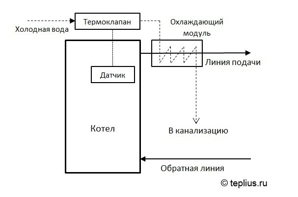
How does a heat exchanger work
When the permissible temperature is exceeded, a thermal valve is triggered by a signal from a thermal sensor.
It supplies cold water from the water supply line to the cooling module, in which excess heat is removed from the coolant. From the cooling module, the heat removed water enters the sewerage system.
Additional circuit
Boiler protection against overheating in systems with forced circulation can also be ensured by means of an additional circuit with natural circulation, to which a storage tank for DHW is connected.
Boiler piping with additional circuit
During normal operation of the system, the pressure created by the circulation pump in the main circuit closes the additional circuit using a check valve, preventing the heat-carrying fluid from circulating in it.
When the pump is turned off for any reason, the forced circulation of the coolant in the main circuit stops and natural circulation begins in the additional circuit. Due to this, the heat-carrying fluid in the system is cooled to the required temperature.
Solid fuel boiler piping
Solid fuel boiler connection diagram
The piping of a solid fuel boiler connected to a closed circuit of the heating system necessarily contains a boiler safety group, an expansion tank and a circulation pump. Solid fuel boilers do not have a number of safety functions; therefore, the piping of a solid fuel boiler must include the specified safety systems in addition. Safe connection of the boiler is the safety of life and health of households and must ensure the minimum operating temperature of the coolant at the boiler inlet at a level of at least 60 ° C. The heat exchanger should not be subject to large thermal fluctuations - this will prevent unwanted metal deformations and the formation of tar and soot in your boiler. This condition is ensured by the installation of the mixing unit. It will maintain the required temperature of the coolant at the entrance to the solid fuel boiler.
Installation of solid fuel boilers and piping of a solid fuel boiler should be carried out exclusively by specialists. Installing a solid fuel boiler on your own with your own hands is extremely dangerous, especially since such a boiler installation will most likely not be accepted by firefighters. This material on how to connect a solid fuel boiler is intended to acquaint you with the topic so that your choice and control of the installation specialists is more competent.
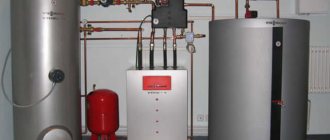
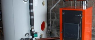
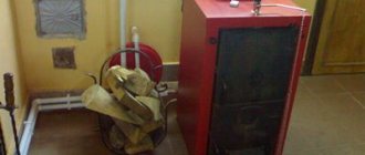
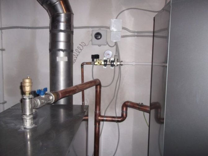
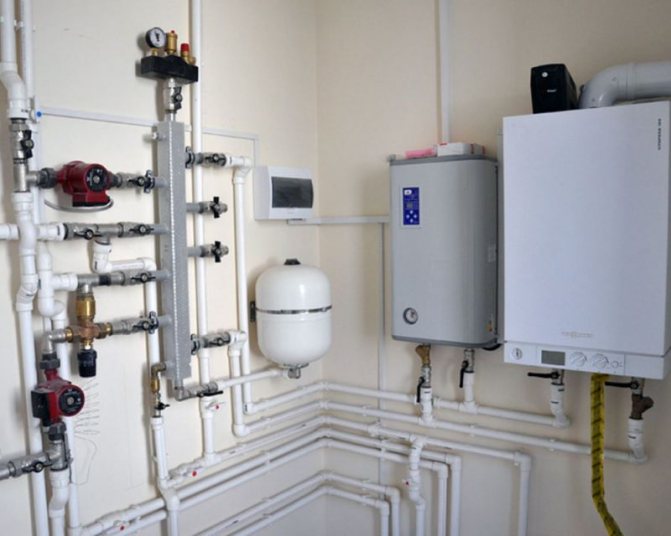
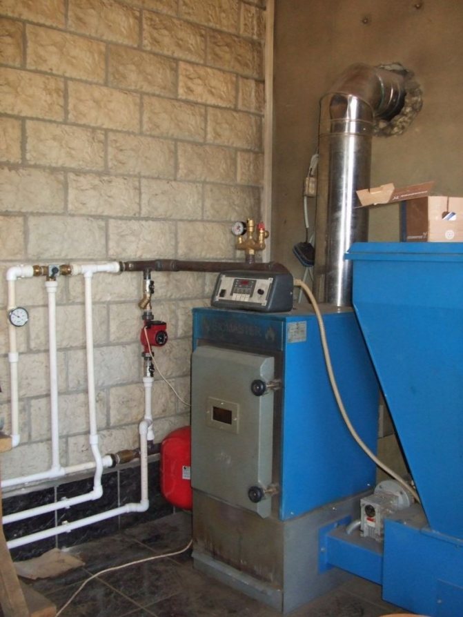
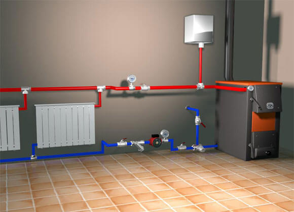
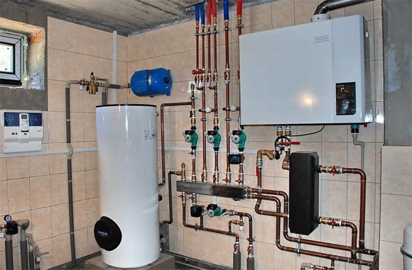
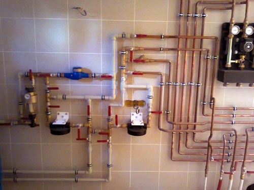
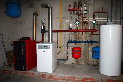
Photo heating installation - Minsk region, Dzerzhinsk
Heating installation: Minsk - drawing of the diagram, Dzerzhinsk - piping of the boiler on site, installation of the chimney. Yes, we start with a pencil drawing of a diagram of a future home heating system with real heating equipment: a 58 kW SAS solid fuel boiler, a S-Tank buffer tank / heat accumulator of 2000 l, an expansion tank of 300 l, a 32-60 grundfos circulation pump. By the way, like everyone else, the client chose chimneys for the Buy Boiler House.
The installation of a solid fuel heating boiler in the photo was carried out by the House of Boilers Bai, Minsk.
Basic strapping schemes
Depending on the number of boiler circuits, the type of heating system and the need to connect additional devices, the piping scheme for a solid fuel boiler can have many options.
Consider the most common ways to connect TT boilers.
To open system with natural circulation
This scheme considered the easiest to implement, since it contains a minimum number of connected devices. Its main advantage is complete independence from the availability of power supply in the house.
Disadvantage: it is impossible to regulate the temperature of the coolant at the outlet of the boiler and the ingress of oxygen into the coolant from an open expansion tank. This can cause accelerated corrosion of the inner surface of metal heating pipes and steel boilers.
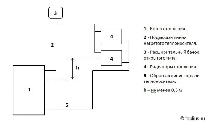
Piping scheme to an open system with natural circulation
It requires special installation rules:
- the heating boiler must be located below the installation level of the heating radiators by at least 0.5 m (to create a stable natural circulation of the coolant);
- pipes should be located at a slope in the direction of the coolant circulation and have a sufficiently large diameter to reduce their hydraulic resistance;
- an open expansion tank must be located at the highest point of the system;
- in the heating system, it is advisable to use a minimum number of valves and control devices that reduce the flow area of the pipelines.
Learn more about the natural heating system.
To a closed system with natural circulation
In this scheme, a closed-type membrane tank is used, usually installed on the return line of the heating system. Its capacity must be at least 10% of the total volume of the coolant used in the heating system.
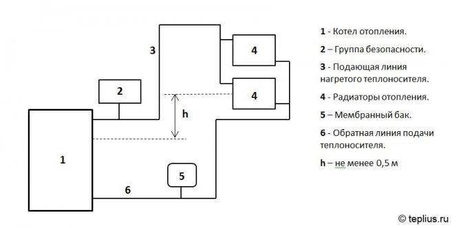
Boiler piping to a closed system with natural circulation
With this scheme of connecting the boiler at the outlet of its supply pipe must be present an air vent and a pressure relief valve that connects with a drain hose to the drain.
These devices can be installed separately or included in the so-called TT safety group of the boiler, which is a separate device.
It includes:
- pressure gauge for visual control;
- pressure relief valve;
- air vent valve for bleeding air from the system.
In some models of solid fuel boilers, these safety elements are already built into the boiler drum.
To a forced circulation system
There is a pump for forced circulation of the heat-carrying fluid through the pipelines of the heating system. The pump is installed, as a rule, on the return line of the heating agent supply between the inlet pipe of the boiler and the membrane tank.
The pump is controlled by a temperature sensor attached to the return line.
Connecting the boiler to a forced circulation system
The use of pumps for forced circulation significantly increases the efficiency of the system due to the use of various temperature control equipment.However, for its operation, it is necessary to be connected to a household power supply, which increases electricity consumption and makes the system volatile from an uninterrupted power supply.
Collector connection method
The collector method of connecting a solid fuel boiler is used in forced circulation systems and provides for the inclusion of special devices in the piping circuit - collectors, also called combs.
They are sections of pipes of larger diameter with one inlet and several outlets, connected to the inlet and outlet of the boiler.
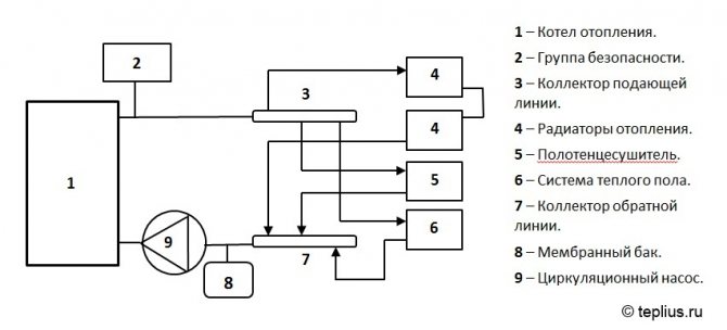
Boiler TT piping with collector system
The advantage of the scheme:
- the possibility of separate connection of each heating device. This makes it possible to supply them with a heat carrier of the same temperature and pressure, as well as to control their work more efficiently.
Disadvantage:
- high consumption of pipes and laboriousness of their laying during the installation of the system.
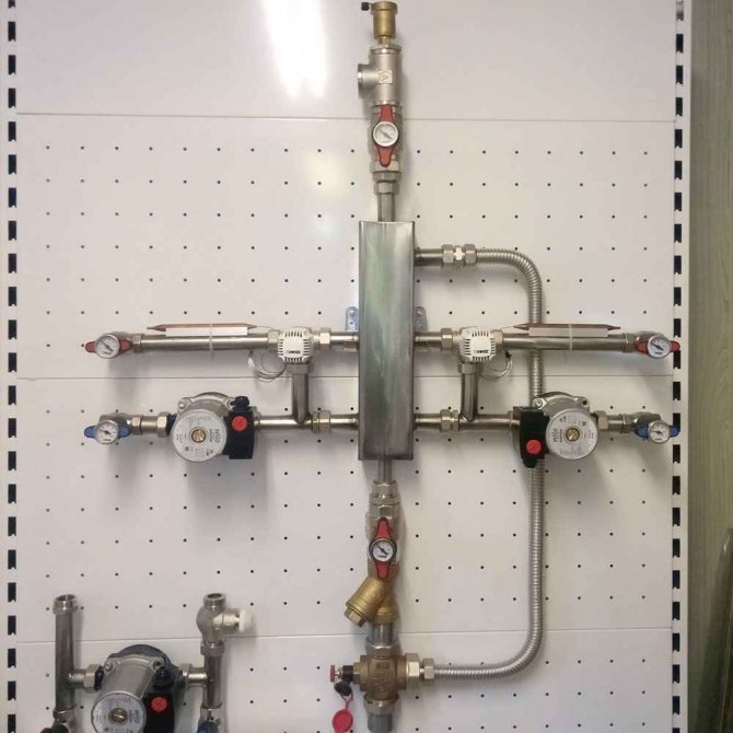
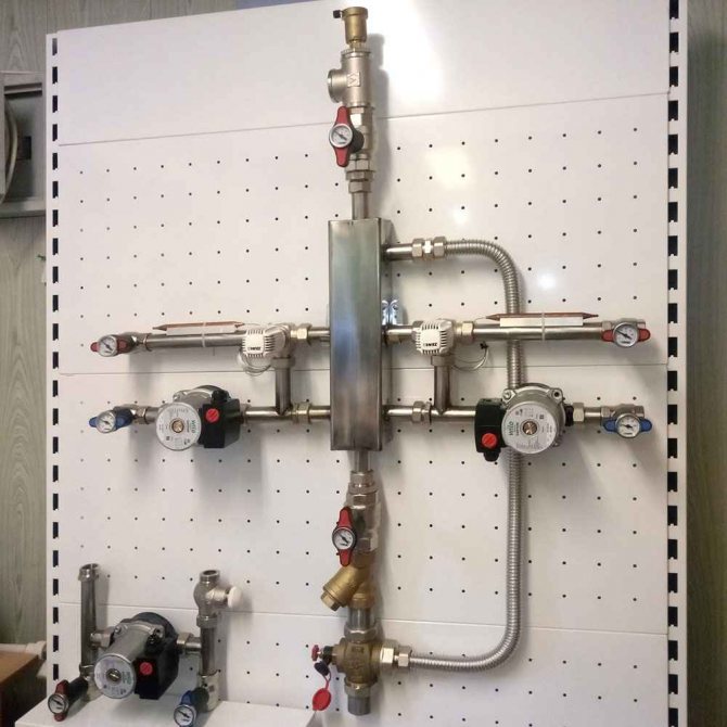
Diagram with a hydraulic arrow
This is a special type of piping using the so-called hydraulic arrow, which is a vertical large diameter pipe connected to the inlet and outlet of the boiler.
Heating devices can be connected to the inputs and outputs of the hydraulic arrow at different heights.
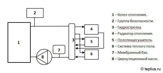
Diagram with a hydraulic arrow
This method of connecting heating devices allows you to select for each of them the optimal temperature of the coolant at the inlet and outlet.
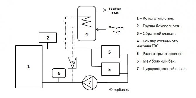
To a system with an indirect domestic hot water boiler
The piping of a solid fuel boiler according to this scheme can be used in systems with any type of coolant circulation.
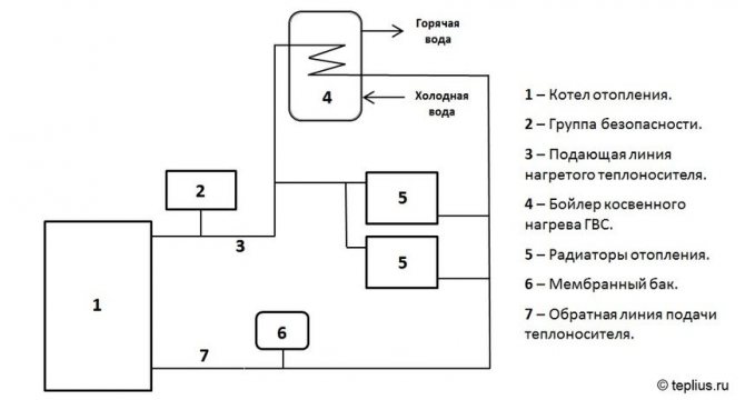
Connection to a system with a domestic hot water boiler
The boiler output flow line is connected in parallel to the heating batteries and a heat exchanger (coil) built into a separate insulated tank (boiler), in which water for the DHW system is heated. Thus, the functionality of the TT boiler is expanded, allowing, during its operation, to additionally provide hot water supply to the house.
An automatic valve can be installed at the inlet to the DHW heat exchanger, which shuts off the supply of heat carrier to it when the water is heated in the boiler as required.
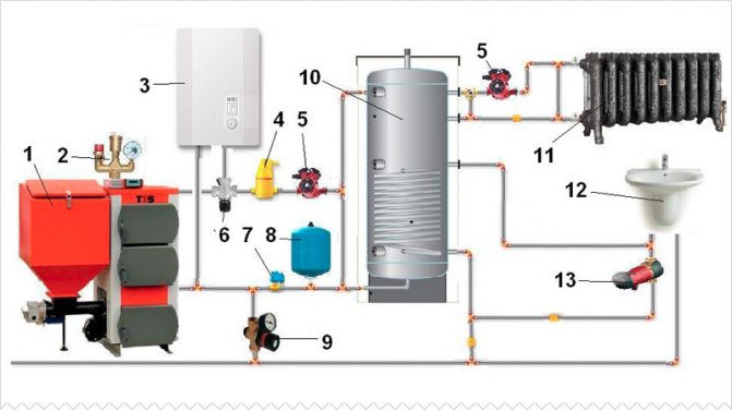
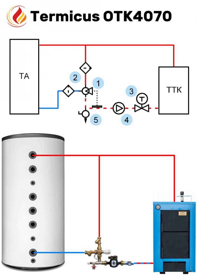
To a system with a heat accumulator
This connection diagram can be used in systems with any type of coolant circulation.
During the strapping process, two circulation circuits are formed:
- between the boiler and the heat accumulator (TA);
- between the TA and the main heating system.
Connecting a solid fuel boiler with a heat accumulator
During the operation of the boiler, the hot coolant enters the TA, which is a separate storage tank with a thermally insulated casing. The TA gradually accumulates the heat generated by the boiler and, if necessary, transfers it to the heating system for heating devices.
After stopping the boiler (stopping fuel combustion), the hot coolant stored in the TA continues to enter the system for some time, depending on the internal volume of the TA.
Such a connection scheme allows to significantly increase the boiler efficiency and reduce fuel consumption, and is also an effective means of protecting the boiler and all system elements from overheating.
Design and installation of boiler TT piping
It is possible to achieve the most efficient operation of the heating system only under the condition that the piping of the solid fuel heating boiler is correctly selected and subsequently completed. All connections must be made with high quality and then the equipment will function reliably for a long period of time.
Each system certainly has a pipeline through which the coolant moves. According to experts, the ideal solution is a circuit with small and large contours, it is also called double-circuit. The one that is smaller is used to heat the coolant (read: "Economical solid fuel double-circuit long burning boiler").
Do-it-yourself piping of the boiler TT should be done with special care, since it allows you to control and regulate the temperature, and, accordingly, select the optimal mode of operation. As a result of the implementation of a properly designed circuit, even the installation of automatic devices can be dispensed with.
The collector option will help to make the operation of the boiler more efficient. There are standard schemes for piping a solid fuel boiler, which are available on this site.
It is unacceptable to use plastic pipes for strapping the TT of the heater. It can only be done using non-combustible materials. Recently, the piping of a solid fuel boiler with polypropylene has become in demand (read: "Piping a heating boiler with polypropylene: options for implementation").
Piping a solid fuel boiler, see an example in the video:
A few tips from professionals
When choosing a boiler piping scheme, one must not forget about emergency situations.
To fix the problem, you can use the following methods:
- cold water supply from the water supply (this method is rarely used);
- installation of a spare (gravitational) circuit capable of removing heat when the electricity is turned off;
- creation of a two-circuit system with natural circulation (for
Solid fuel boilers for heating a private house - do it yourself connection, drawings
The efficiency of its further operation and service life depend on how correctly the piping of the solid fuel boiler is made. In this respect, wood and coal heat generators differ from all others and require a special approach to the issue.
Therefore, it is worth considering in more detail how to connect a solid fuel boiler when installing a heating system, including with your own hands. The answer to this question, as well as a description of all options for joining the unit with other heat power equipment, you can find in this material.
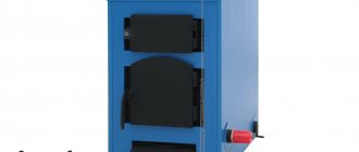
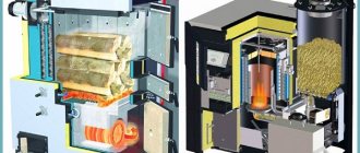
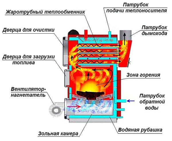
What is the difference between solid fuel boilers
In addition to the fact that these heat sources produce thermal energy by burning various types of solid fuels, they have a number of other differences from other heat generators. These differences are precisely the result of wood burning, they must be taken for granted and always taken into account when connecting the boiler to a hot water heating system. The features are as follows:
- High inertia. At the moment, there are no ways to abruptly extinguish the burnt out solid fuel in the combustion chamber.
- Condensation formation in the firebox. The peculiarity manifests itself when a coolant with a low temperature (below 50 ° C) enters the boiler tank.
Note. The phenomenon of inertia is absent only in one type of solid fuel units - pellet boilers. They have a burner, where wood pellets are fed in metered doses, after stopping the supply, the flame goes out almost immediately.
The danger of inertia consists in the possible overheating of the heater's water jacket, as a result of which the coolant in it boils. Steam is generated, which creates a high pressure, bursting the housing of the unit and part of the supply line. As a result, there is a lot of water in the furnace room, a lot of steam and a solid fuel boiler unsuitable for further operation.
A similar situation can arise when the piping of the heat generator is not done correctly. Indeed, in fact, the normal operating mode of wood-burning boilers is the maximum, it is at this time that the unit reaches its passport efficiency. When the thermostat reacts to the heating agent reaching a temperature of 85 ° C and closes the air damper, combustion and smoldering in the firebox still continues. The water temperature rises another 2-4 ° C, or even more, before its growth stops.
In order to avoid overpressure and a subsequent accident, an important element is always involved in the piping of a solid fuel boiler - a safety group, more details about it will be discussed below.
Another unpleasant feature of the unit's operation on wood is the appearance of condensation on the inner walls of the firebox due to the passage of an unheated coolant through the water jacket. This condensate is not God's dew at all, since it is an aggressive liquid, from which the steel walls of the combustion chamber quickly corrode. Then, mixing with the ash, the condensate turns into a sticky substance, it is not so easy to tear it off the surface. The problem is solved by installing a mixing unit in the piping of a solid fuel boiler.
Such plaque serves as a heat insulator and reduces the efficiency of a solid fuel boiler.
For owners of heat generators with cast iron heat exchangers that are not afraid of corrosion, it is early to breathe a sigh of relief. They can expect another trouble - the possibility of destruction of cast iron from a temperature shock. Imagine that in a private house the electricity was turned off for 20-30 minutes and the circulation pump, which drives water through a solid fuel boiler, stopped. During this time, the water in the radiators has time to cool down, and in the heat exchanger - to heat up (due to the same inertia).
Electricity appears, the pump turns on and directs the cooled coolant from the closed heating system into the heated boiler. From a sharp temperature drop, a temperature shock occurs at the heat exchanger, the cast-iron section cracks, and water runs to the floor. It is very difficult to repair, it is not always possible to replace the section. So, even in this situation, the mixing unit will prevent an accident, which will be discussed later.
Emergency situations and their consequences are described not in order to scare users of solid fuel boilers or induce them to buy unnecessary elements of piping circuits. The description is based on practical experience that must always be considered. With the correct connection of the heating unit, the likelihood of such consequences is extremely low, almost the same as for heat generators using other types of fuel.
How to connect a solid fuel boiler
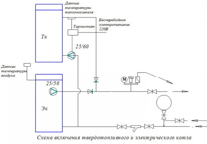
The canonical scheme for connecting a solid fuel boiler contains two main elements that allow it to function reliably in the heating system of a private house. This is a safety group and a mixing unit based on a three-way valve with a thermal head and a temperature sensor, shown in the figure:
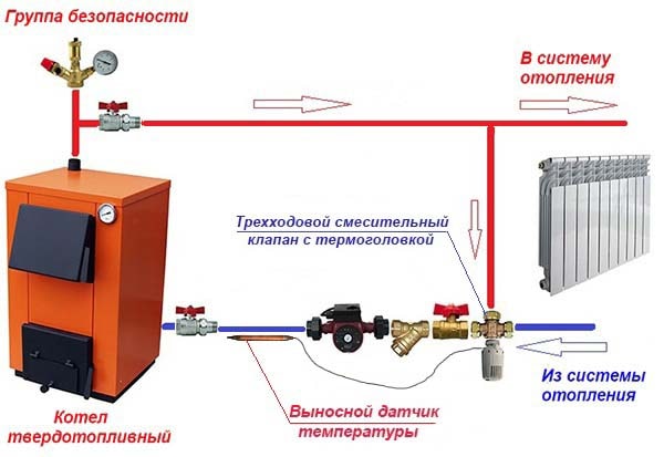
Note. The expansion tank is not conventionally shown here - it must be connected to the return line of the heating system in front of the pump (in the direction of water flow).
The presented diagram shows how to connect the unit correctly and is used with any solid fuel boilers, including pellet ones. You can find various general heating schemes - with a heat accumulator, an indirect heating boiler or a hydraulic arrow, on which this unit is not shown, but it must be there. The method of protection against moisture loss in the firebox is discussed in detail in the video:
The task of the safety group, installed directly at the outlet of the supply pipe of a solid fuel boiler, is to automatically release the pressure in the network when it rises above the set value (usually - 3 Bar). The safety valve is engaged in this, and in addition to it, the element is equipped with an automatic air vent and pressure gauge. The first releases the air that appears in the coolant, the second serves to control the pressure.
Attention! On the section of the pipeline between the safety group and the boiler, it is not allowed to install any shut-off valves.
How the circuit works
The mixing unit, which protects the heat generator from condensation and temperature extremes, works according to the following algorithm, starting from kindling:
- The wood is just burning up, the pump is on, the valve on the heating system side is closed.The coolant circulates in a small circle through the bypass.
- When the temperature in the return pipeline rises to 50-55 ° C, where there is a remote-mounted sensor, the thermal head, at its command, begins to press on the stem of the three-way valve.
- The valve slowly opens and cold water gradually enters the boiler, mixing with hot water from the bypass.
- As all the radiators warm up, the total temperature rises and then the valve closes the bypass completely, passing the entire coolant through the heat exchanger of the unit.
An important nuance. Paired with a 3-way valve, a special head with a sensor and a capillary is installed, designed to regulate the water temperature in a certain range (for example, 40 ... ... 80 degrees). A conventional radiator thermal head will not work.
This piping scheme is the simplest and most reliable, its installation can be easily done with your own hands and thus ensure the safe operation of a solid fuel boiler. There are a couple of recommendations regarding this, especially when tying a wood heater in a private house with polypropylene or other polymer pipes:
- Make the section of the pipe from the boiler to the safety group of metal, and then lay plastic.
- Thick-walled polypropylene does not conduct heat well, which is why the patch sensor will openly lie, and the three-way valve will lag behind. For the unit to work correctly, the section between the pump and the heat generator, where the copper bulb is located, must also be metal.
Another point is the location of the circulation pump. It is best for him to stand where he is shown in the diagram - on the return line in front of the wood-burning boiler. In general, you can put the pump on the supply, but remember what was mentioned above: in an emergency, steam may appear in the supply pipe. The pump cannot pump gases, therefore, when steam enters it, the circulation of the coolant will stop. This will accelerate a possible explosion of the boiler, because it will not be cooled by the water flowing from the return.
A way to reduce the cost of strapping
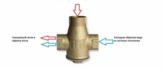
The condensation protection circuit can be reduced in cost by installing a three-way mixing valve of a simplified design, which does not require the connection of a patch temperature sensor and thermal head. A thermostatic element is already installed in it, set to a fixed temperature of the mixture ° C, as shown in the figure:
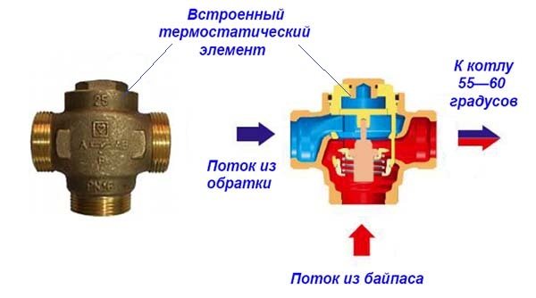
Special 3-way valve for HERZ-Teplomix solid fuel heating units
Note. Many well-known brands such as Herz Armaturen, Danfoss, Regulus and others produce similar valves that maintain a fixed temperature of the mixed outlet water and are intended for installation in the primary circuit of a solid fuel boiler.
The installation of such an element definitely allows you to save on the piping of the TT-boiler. But at the same time, the possibility of changing the temperature of the coolant with the help of the thermal head is lost, and its deviation at the outlet can reach 1-2 ° C. In most cases, these disadvantages are insignificant.
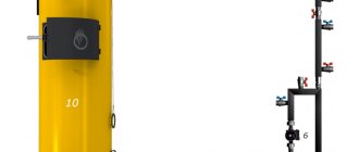
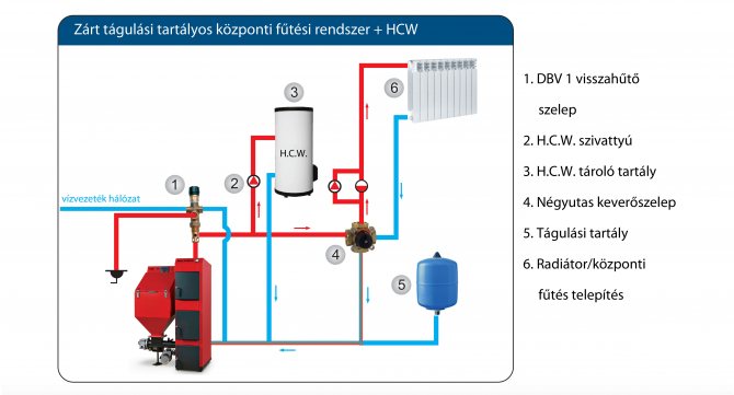
Option of piping with a buffer tank
The presence of a buffer tank is highly desirable for the operation of a boiler on solid fuels and here's why. In order for the unit to function efficiently and produce heat with the efficiency declared in the passport (from 75 to 85% for different types), it must operate at maximum mode. When the air damper is closed in order to slow down the combustion, there is a lack of oxygen in the firebox and the efficiency of burning firewood decreases. At the same time, emissions of carbon monoxide (CO) into the atmosphere increase.
For reference. It is precisely because of emissions in most European countries that it is prohibited to operate solid fuel boilers without a buffer tank.
On the other hand, at maximum combustion, the temperature of the coolant in modern heat generators reaches 85 ° C, and one load of firewood lasts only 4 hours. This does not suit many owners of private houses.The solution to the problem is to put a buffer tank and include it in the piping of the TT-boiler in such a way that it serves as a storage tank. Schematically it looks like this:
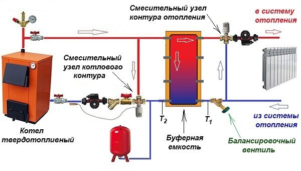
By measuring the temperature of T1 and T2, it is possible to adjust the layer-by-layer loading of the vessel with a balancing valve.
When the firebox is burning with might and main, the buffer tank accumulates heat (in technical language - it is loaded), and after damping it gives it to the heating system. To control the temperature of the coolant supplied to the radiators, a three-way mixing valve and a second pump are also installed on the other side of the storage tank. Now it is not at all necessary to run to the boiler every 4 hours, because after the firebox decays, the heating of the house will provide a buffer tank for some time. How long depends on its volume and heating temperature.
For reference. Based on practical experience, the capacity of the heat accumulator can be determined as follows: a private house with an area of 200 m² will need a tank with a volume of at least 1 m³.
There are a couple of important nuances. In order for the piping scheme to work safely, you need a solid fuel boiler, whose power will be enough for simultaneous heating and loading of the buffer tank. This means that the required power is 2 times higher than the calculated one. Another point is the selection of the pump capacity in such a way that the flow rate in the boiler circuit slightly exceeds the amount of flowing water in the heating circuit.
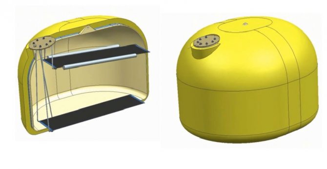
An interesting option for joining a TT-boiler with a home-made buffer tank (it is also an indirect heating boiler) without a pump was demonstrated by our expert in a video:
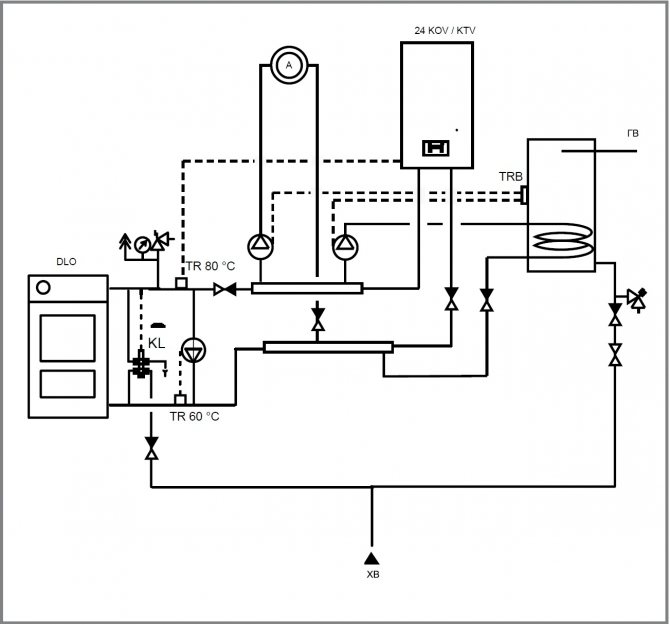
Joint connection of two boilers
To increase the comfort of heating a private house, many owners install two or more heat sources operating on different energy sources. At the moment, the most relevant combinations of boilers for:
- natural gas and wood;
- solid fuels and electricity.
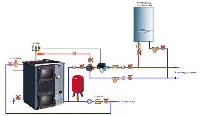
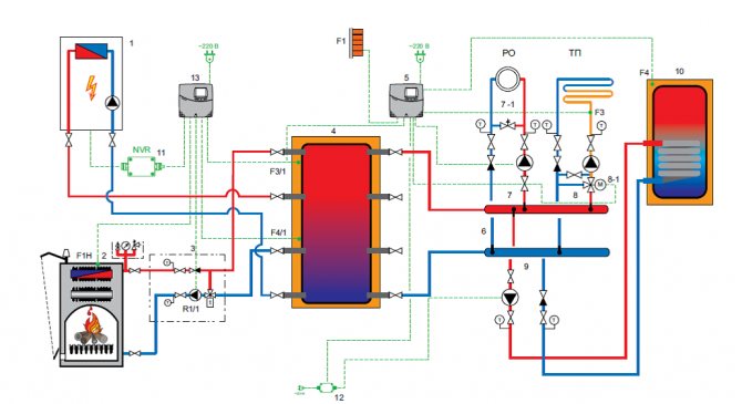
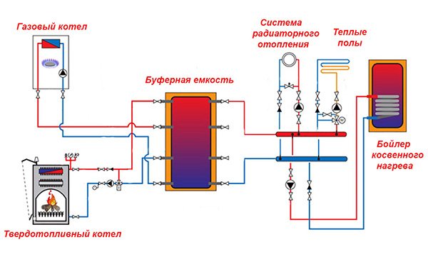
Accordingly, the gas and solid fuel boiler must be connected in such a way that the second automatically replaces the first one after burning the next portion of firewood. The same requirements are put forward for the strapping of an electric boiler with a wood-burning one. It is quite simple to do this when a buffer tank is involved in the piping scheme, since it simultaneously plays the role of a hydraulic arrow, which is shown in the figure.
Advice. You will find information on calculating the volume of the buffer tank in a separate publication.
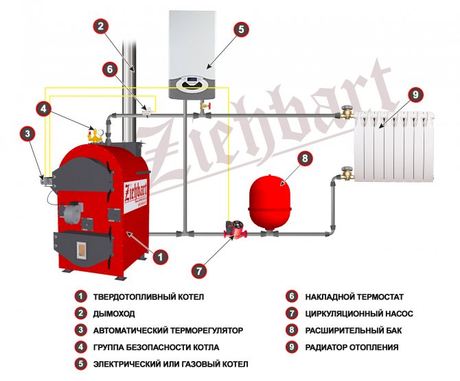
As you can see, due to the presence of an intermediate storage tank, 2 different boilers can serve several distribution heating circuits at once - batteries and underfloor heating, and in addition load an indirect heating boiler. But not everyone installs a heat accumulator with a TT boiler, since it is not a cheap pleasure. For this case, there is a simple scheme, and you can assemble it yourself:
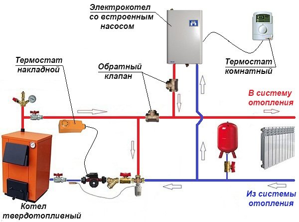
Note. The scheme is valid for both an electric and a gas heat generator operating together with a solid fuel one.
The main source of heat here is the wood-burning heater. After the firewood bookmark burns out, the air temperature in the house begins to drop, which is registered by the room thermostat sensor and immediately turns on the heating with an electric boiler. Without a new load of firewood, the temperature in the supply pipe decreases and the overhead mechanical thermostat turns off the pump of the solid fuel unit. If, after some time, you light it up, then everything will happen in the reverse order. Details about this method of joint connection are described in the video:
Strapping by the method of primary and secondary rings
There is another way of joint piping of a solid fuel boiler with an electric one to provide a large number of consumers. This is a method of primary and secondary circulation rings, which provides for hydraulic separation of flows, but without the use of a hydraulic arrow.Also, for reliable operation of the system, a minimum of electronics is required, and a controller is not needed at all, despite the apparent complexity of the circuit:
The trick is that all consumers and boilers are connected to one primary circulation ring both by the supply pipeline and by the return. Due to the small distance between the connections (up to 300 mm), the pressure drop is minimal compared to the head of the main circuit pump. Due to this, the movement of water in the primary ring does not depend on the operation of the pumps of the secondary rings. Only the temperature of the coolant changes.
Theoretically, any number of heat sources and secondary rings can be included in the main circuit. The main thing is to choose the right pipe diameters and the performance of pumping units. The actual capacity of the main ring pump must exceed the flow in the most "voracious" secondary circuit.
To achieve this, it is necessary to perform a hydraulic calculation and only then it will be possible to select the right pumps, so that an ordinary homeowner cannot do without the help of specialists. In addition, it is necessary to link the work of solid fuel and electric boilers by installing shut-off thermostats, which is described in the following video:
Conclusion
As you can see, it is not so easy to correctly pipate a solid fuel boiler. The question must be treated responsibly and before performing installation and connection work, additionally consult with a specialist whose qualifications are beyond doubt. For example, with someone who gives explanations in the videos presented.
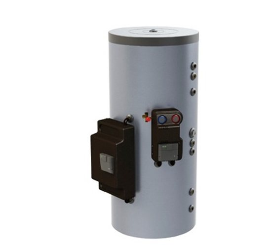
Accumulator tank in the heating system of the house
The accumulator tank in the heating system can also be called a buffer tank. Today, they are increasingly being used in heating systems. Let's take a closer look at what it is.
A storage tank or heat storage is almost a central element in a heating system powered by several heat sources. An intermittent heat source, such as a solid fuel boiler or solar system, heats the water in the storage tank cavity, and can meet the moderate heat needs of the space to be heated. And the share of other sources of thermal energy, which have higher operating costs, will be much lower.
An electric boiler in multi-tariff mode also works much more economically if it is used in tandem with a battery tank, which makes it possible to save as much energy as possible at night.
Heating systems with heat pumps are also often equipped with storage tanks.
The heating system, powered by a solid fuel boiler in the presence of a heat accumulator, operates in an optimal mode. The heat carrier enters from the boiler into the capacity of the accumulator tank as hot as possible. And already from the heat accumulator charged by the boiler, the coolant is transferred into the system as needed, and does not depend on whether the boiler is working.
A person using a heat accumulator significantly increases his comfort in terms of heating, even outdated heating systems equipped with a buffer tank are comparable to modern ones in quality. You can load fuel and service the boiler at any time. It is possible to fully automate the heating system after installing the accumulator tank. Heat energy from the tank will be taken in the amount in which it is necessary. The accumulator tank will protect the boiler from excessive overheating. Installing a heat accumulator makes it possible to use polymer materials, and if the tank is not installed, then this cannot be done.