Calculation of the flow through the heat meter
The calculation of the flow rate of the coolant is carried out according to the following formula:
G = (3.6 Q) / (4.19 (t1 - t2)), kg / h
Where
- Q - thermal power of the system, W
- t1 - temperature of the coolant at the inlet to the system, ° C
- t2 - temperature of the coolant at the outlet of the system, ° C
- 3.6 - conversion factor from W to J
- 4.19 - specific heat capacity of water kJ / (kg K)
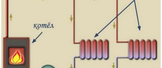
Calculation of the heat meter for the heating system
The calculation of the flow rate of the heating agent for the heating system is carried out according to the above formula, while the calculated heat load of the heating system and the calculated temperature graph are substituted into it.
The calculated heat load of the heating system, as a rule, is indicated in the contract (Gcal / h) with the heat supply organization and corresponds to the heat output of the heating system at the calculated outside air temperature (for Kiev -22 ° C).
The calculated temperature schedule is indicated in the same contract with the heat supply organization and corresponds to the temperatures of the coolant in the supply and return pipelines at the same calculated outside air temperature. The most commonly used temperature curves are 150-70, 130-70, 110-70, 95-70 and 90-70, although other parameters are possible.
Calculation of a heat meter for a hot water supply system
Closed circuit for heating water (through a heat exchanger), a heat meter is installed in the heating water circuit
Q - The heat load on the hot water supply system is taken from the heat supply contract.
t1 - It is taken equal to the minimum temperature of the heat carrier in the supply pipeline and is also specified in the heat supply contract. Typically it is 70 or 65 ° C.
t2 - The temperature of the heating medium in the return pipe is assumed to be 30 ° C.
Closed circuit for heating water (through a heat exchanger), a heat meter is installed in the heated water circuit
Q - The heat load on the hot water supply system is taken from the heat supply contract.
t1 - It is taken equal to the temperature of the heated water leaving the heat exchanger, as a rule it is 55 ° C.
t2 - It is taken equal to the water temperature at the inlet to the heat exchanger in winter, usually 5 ° C.
Calculation of a heat meter for several systems
When installing one heat meter for several systems, the flow through it is calculated for each system separately, and then summed up.
The flow meter is selected in such a way that it can take into account both the total flow rate during the simultaneous operation of all systems, and the minimum flow rate during the operation of one of the systems.
Legislative base of the Russian Federation
valid editors from 06.05.2000
detailed information
| Name document | Order of the State Construction Committee of the Russian Federation of 05/06/2000 N 105 "ON APPROVAL OF THE METHOD FOR DETERMINING THE QUANTITIES OF THERMAL ENERGY AND HEAT CARRIERS IN WATER SYSTEMS OF Municipal Heat Supply" |
| Document type | order, method |
| Host body | gosstroy rf |
| Document Number | 105 |
| Date of adoption | 01.01.1970 |
| Date of revision | 06.05.2000 |
| Date of registration with the Ministry of Justice | 01.01.1970 |
| Status | acts |
| Publication |
|
| Navigator | Notes (edit) |
ORDER of the State Construction Committee of the Russian Federation of 05/06/2000 N 105 "ON APPROVAL OF THE METHOD FOR DETERMINING THE QUANTITIES OF THERMAL ENERGY AND HEAT CARRIERS IN WATER SYSTEMS OF PUBLIC HEAT SUPPLY"
METHOD FOR DETERMINING amount of heat energy and heat carriers in public heating system water (PRACTICAL GUIDE TO THE RECOMMENDATIONS ON THE ORGANIZATION OF ACCOUNTING heat and heat carriers in enterprises, institutions and organizations HOUSING AND COMMUNAL SERVICES AND budgetary sphere)
1. Introduction
1. "Methodology for determining the amounts of heat energy and heat carrier in water systems of municipal heat supply" (Methodology) was developed in order to:
- implementation of the Decree of the Government of the Russian Federation of 08.07.97 N 832 "On improving the efficiency of energy resources and water use by enterprises, institutions and organizations of the budgetary sphere" and "Main directions and mechanism of energy saving in the housing and communal services of the Russian Federation";
- implementation of heat energy and heat carrier metering in accordance with applicable rules;
- monitoring the quality of heat energy and heat carrier, compliance with heat supply and heat consumption regimes, as well as documenting their indicators.
2. This Methodology was developed in the development of "Recommendations for the organization of accounting for heat energy and heat carriers at enterprises, institutions and organizations of housing and communal services and the budgetary sphere" as a practical guide for municipal heat supply organizations producing and supplying heat and heat carrier to consumers ( subscribers), as well as for subscribers - legal entities, heat supply of which is carried out by water systems of municipal heat supply.
The Methodology uses the following basic concepts:
- the balance of heat energy in the heat supply system (heat balance) - the result of the distribution of heat energy supplied by the heat source (sources), taking into account losses during transportation and distribution to the boundaries of operational responsibility and used by subscribers;
- the balance of the heat carrier in the heat supply system (water balance) - the result of the distribution of the heat carrier (network water) released by the heat source (s), taking into account losses during transportation to the boundaries of operational responsibility, and used by subscribers;
- settlement period - the period of time established by the heat supply agreement, for which the consumed heat energy and consumed heat carrier must be determined and fully paid by the subscriber;
- registration - display of the measured value for a certain time interval in digital form or graphic image;
- meter of heat energy and heat carriers (heat meter) - a measuring instrument designed to measure the released (consumed) heat energy and heat carrier, which have passed through the supply (supply) and return (outlet) pipelines of an element of heat supply or heat consumption systems (object of measurement); heat meters are subdivided into one-, two- and multi-stream, depending on the number of components of their primary flow converters, and into two-, three- and multipoint - depending on the number of components of their primary temperature converters;
- heat carrier meter (hot water, cold water) - a measuring device designed to measure the mass (volume) of the heat carrier for a certain period of time;
- metering of heat energy and heat carrier - determination of the amount of heat energy and heat carrier for the calculation between the heat supply organization and subscribers;
- metering unit for heat energy and coolant (metering unit) - a set of duly certified measuring instruments and systems and other devices intended for commercial metering of thermal energy and coolant;
- normative coolant leakage - coolant leakage, the size of which does not exceed the value regulated by the requirement of the Rules for the Technical Operation of Power Plants and Networks of the Russian Federation;
- technological losses of the coolant - losses of the coolant caused by technological solutions and the technical level of the equipment used;
- the leakage of the coolant is above the standard established - the drain of the coolant, the fact, localization and size of which are formalized by the relevant act;
- excess coolant leak, unidentified - coolant leak, the size of which exceeds the values regulated by regulatory documents, the localization and size of which are not fixed.
2. General provisions
4. The supplied or consumed heat energy, Gcal (GJ), is determined by one of the following formulas:
| (1) |
| (2) |
| (3) |
| (4) |
Where
m_1 and m_2 - mass flow rate of the coolant in the supply and return pipelines, t / h;
h_1, h_2 and h_хв are the enthalpy (specific heat content) of the coolant in the supply and return pipelines, as well as the initial cold water supplied to the heat source to recharge the heating network, kcal / kg (kJ / kg);
n is the duration of the billing period, h,
or
| (1a) |
| (2a) |
| (3a) |
| (4a) |
Where
V_1 and V_2 - volumetric flow rate of the heating agent in the supply and return pipelines, m3 / h;
t_1, t_2 and t_хв are the temperature of the coolant in the supply and return pipelines, as well as the initial cold water used to recharge the heating network at the heat supply source, ° С;
К_t - heat coefficient according to the international recommendation of the OIML R75 or other NTD, Gcal / ° Cm3 (GJ / ° Cm3).
5. Conversion of the volumetric flow rate of the coolant (m3 / h) into mass (t / h) is carried out according to the formula:
| m = V ro 10 (-3), | (5) |
Where
V is the volumetric flow rate of the coolant, m3 / h;
ro is the density of the coolant at its measured temperature and pressure, kg / h.
6. The values of density and enthalpy of water are determined on the basis of measurements of its temperature and pressure using the GSSSD tables "Density, enthalpy and viscosity of water". When determining the values of density and enthalpy of hot water (heat carrier) in the supply and return pipelines of the heating network at temperatures in the range from 30 to 150 ° C, the dependence of the density and enthalpy of water on pressure is not taken into account, because this dependence is insignificant and can be neglected. However, in the case of determining the values of density and enthalpy of cold water used for the preparation of make-up water at a heat supply source, at temperatures from 0 to 30 ° C, the water pressure must be taken into account due to the fact that in this range the dependence of the enthalpy of water is significant from the point of view of the requirements imposed on to errors in measuring the amounts of supplied and consumed heat energy and coolant. In this regard, it is necessary at the heat supply source, in addition to the temperature, to also record the pressure of the initial cold water.
7. The amount of released or consumed coolant, t, is determined by the formula:
| (6) |
8. The recommendations given below for determining the amounts of consumed heat energy and heat carrier correspond to the placement of metering units on the border of the balance sheet belonging to the heat supply organization and subscribers. In the event that the metering unit for heat energy and heat carrier is not located at the border of the balance sheet, it is necessary to take into account the losses of heat energy and heat carrier in the section of the heat network between the location of the metering unit and the specified boundary, the size of which is determined by calculation (Section 7) and is indicated in the contract heat supply.
9. The technique is developed for cases:
1) the metering method, when all information for determining the amounts of heat energy and heat carrier is taken only as a result of measurements;
2) the instrument-calculation method of accounting, when part of the information for determining the amounts of consumed heat energy and coolant is taken as a result of measurements at the metering unit, the unmeasured part - from other sources of information about the values of the quantities required for determination;
3) the calculation method of accounting, when all information for determining the amounts of consumed heat energy and heat carrier is taken from the relevant information sources without direct measurements.
3. Determination of the amounts of heat energy and heat carrier released into the heating network by the heat source
10. Determination of the amounts of heat energy supplied to the heating network to the heat carrier at the heat source should be carried out only by the instrumental method.
11. The supply of heat energy must be determined for each of the outputs of the heat network separately, implementing one of the above formulas - (1) - (4) or (1a) - (4a). In these formulas:
m_1 and m_2 (V_1 and V_2) - mass (volumetric) flow rate of the coolant in the supply and return pipelines at the outlets of the heat source, t / h (m3 / h),
h_1, h_2 and h_хв (t_1, t_2 and t_хв) are the enthalpy (temperature) of the heat carrier in the supply and return pipelines of the heating network at the outlets of the heat source and initial cold water used for the preparation of make-up water, kcal / kg (kJ / kg) (° FROM);
n is the duration of the supply of heat energy and coolant in the billing period, h.
12. The total supply of heat energy by a heat source having several outputs of the heating network is determined by summing up the results for all outputs of the heating network.
13. The amount of heat carrier released into the heating network and non-returned at the heat source for the billing period is determined by the readings of heat meters (water meters) according to the formula:
| (6a) |
14. When determining the heat energy and coolant released to the heating network, it is permissible instead of the difference m_1 - m_2 (or V_1 - V_2) to use the measured value of the mass (volume) of make-up water m_n (or V_n) sent to the heating network, provided that the condition m_n < = m_1 - m_2 (or V_п <= V_1 - V_2).
15. If the metering unit at the heat source is equipped with a two-flow three-point heat meter that measures the values of m_1, m_2, t_1, t_2 and t_xv and implements formula (1), the amount of released heat energy is determined directly by the heat meter.
16. When equipping a metering unit of a heat source with recording devices of flow rate (or water meters) and temperature of the coolant installed on the supply, return pipelines and on the make-up pipeline, the amount of released heat energy is determined from the results of measurements in accordance with formulas (1) - (4) or (1a) - (4a).
4. Determination of the amounts of heat energy and coolant consumed by subscribers, with the metering method
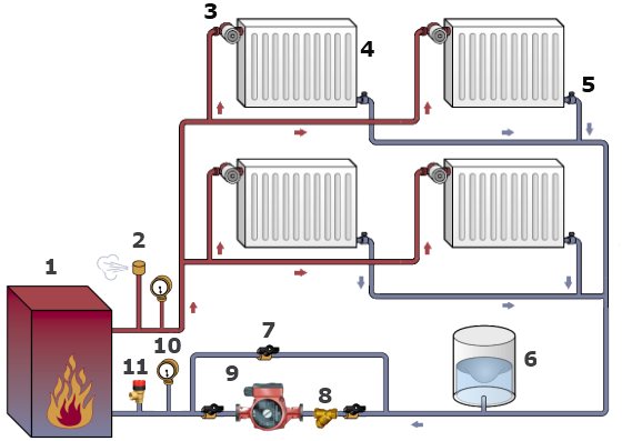
17. When equipping the metering bridle with registering devices of flow rate (or water meters) and temperature of the coolant (Fig. 1a, 1b), the amount of consumed thermal energy is determined according to one of the formulas given in clause 4
Figure 1a
Figure 1b
The values of the quantities m_1, m_2, as well as h_1, h_2 should be taken according to the results of measurements at the metering unit of heat consumers, the value of h_хв - as the average value for the reporting period according to the results of measurements at the heat source.
If the equality of the flow rates of the coolant in the supply and return pipelines (m_1 = m_2 = m) is revealed, the determination of the consumed thermal energy, Gcal (GJ), can be made according to the formula:
| (7) |
The following designations are adopted for the figures:
Explanation of designations
18. When equipping a subscriber's metering unit with a two-flow two-point heat meter (Fig. 2), the amount of consumed heat energy is determined according to the formula:
| (8) |
Where
Q_meas - the amount of heat energy measured by the heat meter for the billing period, Gcal (GJ);
Q_n - heat energy not accounted for by the heat meter due to the fact that the actual enthalpy of the initial cold water used to recharge the heating network at the heat source is not determined by the heat meter, Gcal (GJ).
Figure 2
The value of Q_n, Gcal (GJ), is determined depending on the formula implemented by the heat meter:
1) at
unaccounted thermal energy is determined by the formula:
| (9) |
Where
m_1 and m_2 - determined by the readings of the heat meter, t;
h_хв - is taken as the average value of the enthalpy of the initial cold water for the calculation period according to the results of measurements at the heat source, kcal / kg (kJ / kg);
2) when a fixed temperature (enthalpy) of cold source water is introduced into a heat meter using a fixed temperature (enthalpy) at a heat supply source t_xv.z (h_xv.z) and the heat meter implements the formula
| (10) |
unaccounted thermal energy is determined by the formula:
| (11) |
19. When equipping a subscriber's metering unit with a single-flow two-point heat meter on one of the pipelines and a water meter on the other (Fig. 3a, 36), the amount of consumed thermal energy, Gcal (GJ), is determined by the formula (8), where Q_n is the thermal energy of the consumed heat carrier, not returned to the heating network.
Figure 3a
Figure 3b
The value of the Q_n value is determined depending on the installation location of the heat carrier flow transducer and the formula implemented by the heat meter:
1) at
| (7a) |
which corresponds to the installation of the heat carrier flow rate transducer on the supply pipeline (Fig. 3a), -
| (9a) |
In this formula, the values of m_1, h_1 and h_2 are determined by a heat meter, m_2 by a water meter, h_хв is taken as an average value based on the results of measurements at a heat source;
2) at
| (7b) |
which corresponds to the installation of the heat carrier flow rate transducer on the supply pipeline (Fig. 3b), -
| (9b) |
Here the values m_2, h_1 and h_2 are determined by a heat meter, m_1 by a water meter, h_хв is taken as an average value based on the results of measurements at a heat source.
When the equality of the values of the flow rate of the coolant in the supply and return pipelines (m_1 = m_2 = m) is found, the amount of consumed thermal energy is determined by the readings of the heat meter (Q = Q_meas).
20. The amount of consumed coolant is determined for the billing period according to the results of measurements at the metering unit according to the formula (6).
5. Determination of the amounts of heat energy and heat carrier consumed by subscribers, with the instrument-calculation method of accounting
21. In heat consumption systems without direct tapping for hot water supply from the heating network, when equipping the metering unit with one single-flow two-point heat meter, with the obligatory installation of its heat carrier flow rate converter on the supply pipeline (Fig. 4), the determination of the consumed heat energy is carried out according to the formula (8) , in which the value of the quantity Q_meas is determined by the formula (7) at m = m_1, and the value of the quantity Q_n is determined by the formula (9b).
In this case, the amount of consumed heat carrier (not returned to the heating network) Delta m = m_1 - m_2, is determined from the water balance of the heat supply system according to the method described in Section 7, and h_xв - as an average value based on the results of measuring the temperature and pressure of the initial cold water at the heat source ...
Figure 4
22. When the metering unit is equipped with registering flow meters or water meters on the supply and return pipelines (Fig. 5), the determination of the consumed heat energy in heat consumption systems, both with and without direct water intake for hot water supply, is performed according to the formula (1).
Figure 5
The values m_1 and m_2 are determined according to the readings of the devices at the metering unit, and h_1 and h_2 - according to the average values of the coolant temperature in the supply and return pipelines at the heat source for the billing period, taking into account the decrease in the temperature of the coolant in the pipelines in the heating network section from the source to the considered consumer. In this case, the dimensions of the corresponding decrease in the temperature of the coolant in the supply and return pipelines of the heating network in this section must be indicated in the heat supply agreement.The average value of h_хв should be taken according to information on measurements of the temperature and pressure of the initial cold water used to recharge the heating network at the heat source.
The determination of the amount of coolant used by the consumer for the billing period is made according to the difference in the readings of the installed devices according to formula (6)
23. When equipping a metering unit only with a water meter on the supply pipeline (or a registering flow meter) in a heat consumption system without direct water intake for hot water supply (Fig. 6), the amount of heat energy is determined according to formula (2).
In this case, the value m_1 is taken according to the readings of the installed device, and the value Delta m = m_1 - m2, which is a coolant leak, is determined from the water balance of the heat supply system (Section 7). Enthalpy values h_1, h_2 and h_хв should be taken in accordance with the instructions in clause 22.
Figure 6
6. Determination of the amounts of heat energy and heat carrier consumed by subscribers, in the calculation method of accounting
24. In case of temporary absence of metering devices from the heat energy consumer (subscriber), or in the period before their installation, the calculation method of metering is used to determine the consumed heat energy and heat carrier.
25. The amount of heat energy and heat carrier used by an individual subscriber without metering devices is considered as the corresponding part of the total amount of heat energy and heat carrier consumed by all subscribers without metering devices in the heat supply system.
The total amount of heat energy and heat carrier consumed during the billing period by all subscribers without metering devices is determined from the heat and water balances of the heat supply system, and by an individual consumer - in proportion to its calculated hourly heat and mass (volumetric) loads specified in the heat supply agreement, taking into account the difference in the nature of heat consumption: heating and ventilation heat load is variable and depends on meteorological conditions, the heat load of hot water supply during the heating period is constant.
Heat losses through the insulation of pipelines in the sections of the heat network that are on the balance sheet of the corresponding subscriber are included in the amount of heat consumed by this subscriber, as well as losses of heat energy with all types of leakage and drainage of the heat carrier from the heat consumption systems and pipelines of its section of the heat network.
26. The total heat consumption of all subscribers without metering devices Q_p in all heat consumption systems, including all types of heat losses in the sections of the heat network that are on the balance of these subscribers, is determined from the heat balance equation of the heat supply system:
| (12) |
Where
Q_other - heat energy supplied by the heat supply source to the heating network for the billing period, Gcal (GJ);
Q_п is the total amount of heat energy consumed by subscribers whose heat consumption is determined by instrumental and instrumental-calculation methods of accounting, including all types of heat losses in the sections of the heat network that are on the balance of these subscribers, for the billing period, Gcal (GJ);
Q_out is the loss of heat energy by pipelines of the heating network of the heat supply organization associated with all types of leakage and drainage of the coolant, Gcal (GJ);
O_iz - heat losses by pipelines of a heating network of a heat supplying organization through thermal insulation, Gcal (GJ);
27. Losses of heat energy Q_yт in formula (12) are made up of heat losses due to the standard and technological leakage of the heat carrier, as well as heat losses due to the excess established (fixed by the relevant acts) and unidentified leakage of the heat carrier from the pipelines of the heating network of the heat supply organization for the billing period.
The quantities making up the formula (22) are determined:
Q_otp - according to the instructions in section 3;
Q_п - according to the instructions in sections 4 and 5;
Q_out, Q_from - according to the instructions in section 7.
28. The total amount of heat energy accounted for in the heat balance of the heat supply system for the heat consumption of subscribers without metering devices consists of the heat energy used by these subscribers for heating and ventilation, hot water supply, as well as heat energy lost in the sections of the heat network located on their balance, i.e. heat losses through the insulation of pipelines and with the lost coolant, which is associated with all types of its leakage and discharge:
| (13) |
Where
Q_p.о-в - heat energy used for the billing period by subscribers without metering devices to cover the heating and ventilation heat load, Gcal (GJ);
Q_р.г - the same for hot water supply, Gcal (GJ);
Q_р.from - losses of heat energy through the insulation of pipelines at the section of the heating network, which is on the balance of subscribers without metering devices, for the billing period, Gcal (GJ);
Q_р.out - heat energy losses with all types of coolant leakage from heat consumption systems of subscribers without metering devices and sections of the heating network on their balance sheet for the billing period, Gcal (GJ).
29. To determine the amount of heat energy used by each of the considered subscribers for heating and supply ventilation, it is necessary to preliminarily allocate by calculation from the total amount of heat energy accounted for in the heat balance of the heat supply system for these subscribers, a part of the heat energy used by them for hot water supply, as well as part of the heat energy lost in the sections of the heat network that are on their balance sheet, in accordance with the expression:
| (13a) |
The amount of heat energy used by subscribers without metering devices for hot water supply is determined by the average hourly values of their hot water supply load (Appendix 1).
The values of Q_p.from and Q_p.yt are determined according to the instructions in Section 7.
30. Thermal energy, Gcal (GJ), used during the billing period for heating and supply ventilation by a subscriber without metering devices is determined in proportion to his calculated hourly heat heating and ventilation load according to the formula:
| (14) |
Where
Q_р.о-в - total heat consumption of all subscribers without metering devices for heating and supply ventilation for the billing period, Gcal (GJ);
Q_р.о-в.д is the calculated hourly heat load of the considered subscriber for heating and supply ventilation, included in the heat supply contract, Gcal / h (GJ / h);
The sum of Q_r.o-v.d is the total calculated hourly heat load for heating and supply ventilation of all subscribers without metering devices, Gcal / h (GJ / h).
Guidelines for determining the estimated hourly heat loads for heating, supply ventilation and hot water supply are given in Appendix 1 to these Recommendations.
31. The total amount of heat energy, Gcal (GJ), consumed by an individual subscriber without metering devices for the billing period is determined as:
| (13b) |
In this formula, the values of the incoming quantities refer to each subscriber without metering devices.
32. The total amount of the heat carrier not returned to the heating network for the billing period by all subscribers without metering devices, in the heat supply system without direct draw-off for hot water supply, ie. part of the total leakage of the coolant in the heat supply system, is determined from the equation of the water balance of the heat supply system:
| (15) |
Where
Delta m_other is the total amount of the heat carrier released into the heating network and not returned to the heat source in the heat supply system (complete leakage), t;
Delta m_p is the amount of coolant not returned to the heating network, determined by the metering devices of subscribers, t;
Delta m_yr.s - the amount of coolant lost in the heating network of the heat supply organization due to all types of leakage, t; determined according to the instructions in section 7.
33.The total amount of coolant not returned to the heating network for the billing period by all subscribers without metering devices in the heat supply system without direct water intake is:
| (16) |
Where
Delta m_t.n - heat carrier losses due to standard leakage from heat consumption systems of subscribers without metering devices and sections of the heating network on their balance sheet for the billing period, t;
Delta m_r.out.sn.pust - the same, due to an unidentified excess leakage, t;
Delta m_r.t - the same, technological, t;
Delta m_r.ut.sn.set - the same, due to the excess established leak, i.e.
The definition of the above values, as well as their values for each subscriber without metering devices, is carried out according to the instructions in section 7.
34. In a heat supply system with direct water withdrawal for hot water supply, the amount of heat carrier not returned to the heat network for the billing period by such subscribers, in addition to the amount of heat carrier that is a leak, includes the amount of heat carrier that is taken from the heat network for hot water supply (water withdrawal):
| (17) |
Where
Delta m_p.g is the amount of coolant taken during the billing period for hot water supply (water intake) by all subscribers without metering devices, i.e.
35. The amount of coolant taken for hot water supply from the heating network by a separate subscriber without metering devices, t, can be determined by calculation according to the average hourly load of hot water supply of the subscriber in question:
| (18) |
Where
m_y.wd is the average hourly load of hot water supply of the considered subscriber under the heat supply contract (calculated water intake), t / h.
Methodological recommendations for determining the average hourly loads of hot water supply of subscribers are given in Appendix 1.
7. Calculated determination of heat energy and heat carrier losses in heat supply systems
36. Heat carrier losses by pipelines of the heating network of the heat supply organization and sections of the heating network of subscribers, as well as their heat consumption systems, for the billing period in the heat supply system without direct draw-off for hot water supply can be represented by a formula similar to formula (16):
| (16a) |
Where
Delta m_y.n - heat carrier losses due to standard leakage, t;
Delta m_out.sn.pust is the loss of the coolant due to an unidentified excess leakage, t;
Delta m_t - technological losses of the coolant, i.e.
Delta m_out.sn.set is the loss of the coolant due to the established excess leakage, i.e.
37. Losses of coolant, t, due to standard leakage from the heating network of the heat supply organization, as well as from heat consumption systems and sections of the heating network of subscribers for the billing period are determined in accordance with clause 4.12.30 "Rules for the technical operation of power plants and networks of the Russian Federation" (2) according to the formula:
| (19) |
Where
V is the capacity of pipelines of the heating network of the heat supply organization, as well as the heating network and heat consumption systems of subscribers, m3;
ro is the density of the heat carrier (network water), kg / m3.
The value of the density of the coolant should be taken in accordance with the average temperature of the coolant in the supply and return pipelines of the heating network (heat consumption systems) for the billing period.
38. The technological losses of the coolant, as well as due to the established excess leakage for the billing period, are determined according to the relevant standards, as well as acts drawn up in connection with these losses.
39. The total losses of the coolant associated with an unidentified excess leakage from the above elements of the heat supply system without direct water intake are determined from the water balance of the heat supply system:
| (20) |
Where
Delta m_other is the total amount of coolant not returned to the heating network in the billing period, t;
Delta m_p.- the total amount of consumed coolant, measured and recorded at subscriber metering stations, t;
Delta m_t.n - the total amount of heat carrier lost due to the standard leak for the reporting period from the heating network of the heat supply organization, sections of the heating network of subscribers, where metering nodes are located not on the boundaries of the balance sheet, sections of the heating network of subscribers and their heat consumption systems that are not equipped metering units, t;
Delta m_t.t is the total amount of coolant lost with a technological leak from the heating network of the heat supply organization, sections of the heating network of subscribers where metering units are located not on the border of the balance sheet, sections of the heating network of subscribers and their heat consumption systems not equipped with metering units, (drawn up relevant acts);
Delta m_t.sn.set is the total amount of coolant lost due to the established excess leakage, drawn up by the relevant acts, i.e.
40. In a heat supply system with direct water intake for hot water supply, the total losses of the coolant for the calculation period associated with an unidentified excess coolant leakage are determined from the equation of the water balance of the heat supply system:
| (20a) |
Where
Delta m_r.g is the total amount of the coolant accounted for during the billing period for the water intake by subscribers without metering devices for the consumed thermal energy and coolant, t, is determined by the formula (18).
41. Heat carrier losses associated with an unidentified excess leakage for the calculation period are determined for the following elements of the heat supply system:
- heating network of a heat supply organization;
- sections of the heating network of subscribers, the metering units of which are not located on the border of the balance sheet;
- sections of the heating network and heat consumption systems of subscribers not equipped with metering devices;
- sections of the heating network to the heat consumption system of subscribers using the instrument-calculation method of accounting due to the fact that in one of the pipelines of the metering unit the amount of coolant is not measured,
42. The total losses of the coolant, t, associated with unidentified excess coolant leaks for the reporting period, are distributed among the elements of the heat supply system in proportion to the capacity of each element in accordance with the formula:
| (21) |
Where
V_el - capacity of an element of a heat supply system (heating network or heat consumption systems of subscribers), m3.
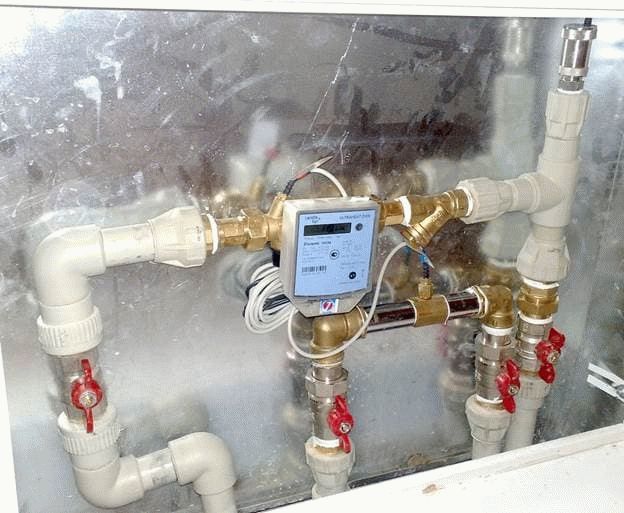
Heat meters
In order to calculate thermal energy, you need to know the following information:
- Liquid temperature at the inlet and outlet of a certain section of the line.
- The flow rate of the liquid that moves through the heating devices.
The flow rate can be determined using heat meters. Heat metering devices can be of two types:
- Vane counters. Such devices are used to meter heat energy, as well as hot water consumption. The difference between such meters and cold water meters is the material from which the impeller is made. In such devices, it is most resistant to high temperatures. The principle of operation is similar for the two devices:
- The rotation of the impeller is transmitted to the accounting device;
- The impeller starts rotating due to the movement of the working fluid;
- The transmission is carried out without direct interaction, but with the help of a permanent magnet.
Such devices have a simple design, but their response threshold is low. And also they have reliable protection against distortion of readings. The anti-magnetic shield prevents the impeller from being braked by the external magnetic field.
- Devices with a differential recorder. Such counters work according to Bernoulli's law, which states that the rate of movement of a liquid or gas flow is inversely proportional to its static movement. If the pressure is recorded by two sensors, it is easy to determine the flow in real time.The counter implies electronics in the construction device. Almost all models provide information on the flow rate and temperature of the working fluid, as well as determine the consumption of thermal energy. You can set up work manually using a PC. You can connect the device to a PC via the port.
Many residents are wondering how to calculate the amount of Gcal for heating in an open heating system, in which hot water can be taken off. Pressure sensors are installed on the return pipe and the supply pipe at the same time. The difference, which will be in the flow rate of the working fluid, will show the amount of warm water that was spent for domestic needs.

General provisions and objectives
In accordance with the main provisions of PP No. 1034 (11/18/2013) with additions made in 2020, the number of measures required in order to properly organize the metering of heat consumption in accordance with legislative norms includes the following:
- equipping multi-apartment residential buildings with general-purpose heat meters that correspond to the characteristics of the parameters set by the Federal Information Fund for Ensuring the Uniformity of Measurements;
- development of design documentation for metering units based on the requirements imposed on them by these Rules, taking into account the terms of the contract for connecting hot water supply and heating to the equipment of the heat supplier;
- commissioning of mounted and empirically tested measuring systems installed at the input of a heat supply source;
- installation and commissioning of a consumer metering unit corresponding to the project;
- proper use of measuring devices of the metering system, including careful monitoring of their serviceability by management companies and prompt elimination of shortcomings in their work by the heat supply organization;
- timely provision of information on heat consumption and organization of energy consumption accounting in case the heat meter is out of order;
- regular check of the technical condition of energy metering systems;
- systematic measurement of those parameters of energy and its carrier, which allow keeping accounting documentation on payment for services and assessing the quality of heat supply;
- constant quality control of the heat energy received by a residential building in the area between the consumer and the heat supplying organization;
- determination of heat and coolant consumption in accordance with these rules;
- observance of methods for calculating and distributing heat losses in the presence or absence of meters between adjacent heating networks.
Commercial metering of the heat resource consumption for heating residential buildings is carried out in order to:
- ensuring mutual settlements between the supplier and consumer of thermal energy;
- improving the quality of heat supply by monitoring the functioning of systems that supply heat energy and consuming installations of residential buildings;
- rationalization of heat consumption in an apartment building through systematic control;
- organization of documentation of parameters: pressure, temperature and volume of the coolant (keeping a log book).
We solve legal problems of any complexity. # Be at home and leave your question to our lawyer in the chat. It's safer this way.
Ask a Question
Heat load duration graph
To establish an economical mode of operation of heating equipment, to select the most optimal parameters of the coolant, it is necessary to know the duration of operation of the heat supply system under various modes throughout the year. For this purpose, graphs of the duration of the heat load are built (Rossander graphs).
The method for plotting the duration of the seasonal heat load is shown in Fig. 4. Construction is carried out in four quadrants. In the upper left quadrant, graphs are plotted depending on the outside temperature tH,
heating heat load
Q,
ventilation
QB
and the total seasonal load
(Q +
n during the heating period of outdoor temperatures tn equal to or lower than this temperature.
In the lower right quadrant, a straight line is drawn at an angle of 45 ° to the vertical and horizontal axes, used to transfer the scale values P
from the lower left quadrant to the upper right quadrant. Heat load duration 5 is plotted for different outdoor temperatures
tn
by the points of intersection of the dashed lines that determine the heat load and the duration of the standing loads equal to or greater than this one.
Area under the curve 5
the duration of the heat load is equal to the heat consumption for heating and ventilation during the heating season Qcr.
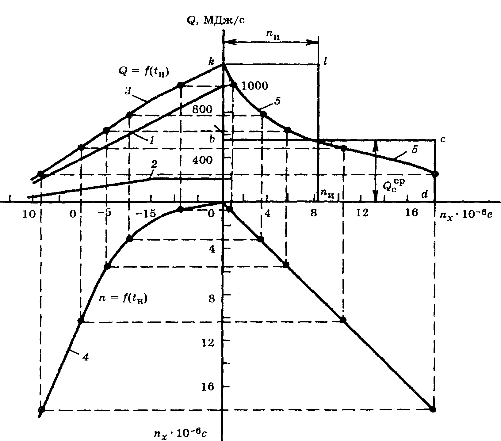
Fig. 4. Plotting the duration of the seasonal heat load
In the case when the heating or ventilation load changes by hours of the day or days of the week, for example, when industrial enterprises are switched to standby heating during non-working hours or ventilation of industrial enterprises does not work round the clock, three curves of heat consumption are plotted on the graph: one (usually a solid line) based on the average weekly heat consumption at a given outside temperature for heating and ventilation; two (usually dashed) based on the maximum and minimum heating and ventilation loads at the same outside temperature tH.
Such a construction is shown in Fig. five.
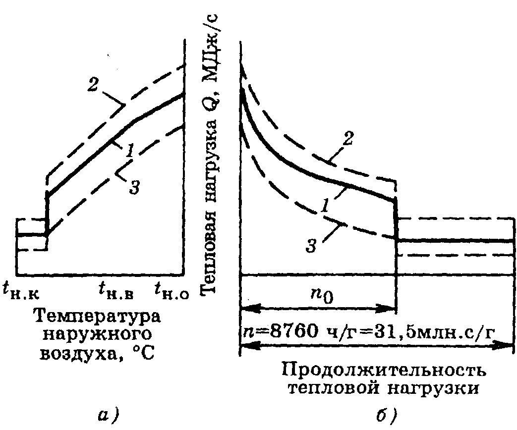
Fig. 5. Integral graph of the total load of the area
but
—
Q
= f (tн);
b
- graph of the duration of the heat load; 1 - average weekly total load;
2
- maximum hourly total load;
3
- minimum hourly total load
The annual heat consumption for heating can be calculated with a small error without accurately taking into account the repeatability of the outside air temperatures for the heating season, taking the average heat consumption for heating for the season equal to 50% of the heat consumption for heating at the design outside temperature tbut.
If the annual heat consumption for heating is known, then, knowing the duration of the heating season, it is easy to determine the average heat consumption. The maximum heat consumption for heating can be taken for rough calculations equal to twice the average consumption.
16
Accurate calculation of heat loss at home
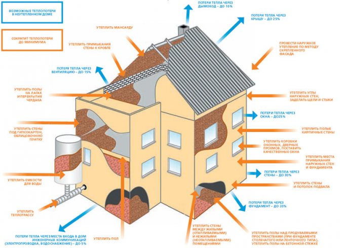
For a quantitative indicator of the heat loss of a house, there is a special value called heat flow, and it is measured in kcal / hour. This value physically shows the heat consumption that is given off by the walls to the environment at a given thermal regime inside the building.
This value depends directly on the architecture of the building, on the physical properties of the materials of the walls, floor and ceiling, as well as on many other factors that can cause the weathering of warm air, for example, improper design of the heat-insulating layer.
So, the amount of heat loss of a building is the sum of all heat losses of its individual elements. This value is calculated by the formula: G = S * 1 / Po * (Tv-Tn) k, where:
- G is the required value, expressed in kcal / h;
- Po - resistance to the process of exchange of thermal energy (heat transfer), expressed in kcal / h, this is m2 * h * temperature;
- Tv, Tn - indoor and outdoor air temperature, respectively;
- k is a decreasing coefficient, which is different for each thermal barrier.
It is worth noting that since the calculation is not made every day, and the formula contains temperature indicators that change constantly, it is customary to take such indicators in an averaged form.
This means that the temperature indicators are taken on average, and for each separate region such an indicator will be different.
So, now the formula does not contain unknown members, which makes it possible to carry out a fairly accurate calculation of the heat losses of a particular house. It remains to find out only the reduction factor and the value of the value of Po - resistance.
Both of these values, depending on each specific case, can be found from the corresponding reference data.
Some values of the reduction factor:
- floor on the ground or wooden logs - value 1;
- attic floors, in the presence of a roof with roofing material made of steel, tiles on a sparse lathing, as well as roofs made of asbestos cement, an attic roof with arranged ventilation - value 0.9;
- the same overlappings as in the previous paragraph, but arranged on a continuous flooring, - a value of 0.8;
- attic floors, with a roof, the roofing material of which is any roll material - value 0.75;
- any walls that separate a heated room from an unheated one, which, in turn, has external walls, - a value of 0.7;
- any walls that separate a heated room from an unheated one, which, in turn, does not have external walls - value 0.4;
- floors arranged above cellars located below the level of the outer ground - value 0.4;
- floors arranged above cellars located above the level of the outer ground - value 0.75;
- floors that are located above basements, which are located below the level of the external ground or higher by a maximum of 1 m - a value of 0.6.
Based on the above cases, you can roughly imagine the scale, and for each specific case that is not included in this list, you can independently choose a reduction factor.
Some values for resistance to heat transfer:

The resistance value for solid brickwork is 0.38.
- for ordinary solid brickwork (wall thickness is approximately 135 mm), the value is 0.38;
- the same, but with a masonry thickness of 265 mm - 0.57, 395 mm - 0.76, 525 mm - 0.94, 655 mm - 1.13;
- for solid masonry with an air gap, with a thickness of 435 mm - 0.9, 565 mm - 1.09, 655 mm - 1.28;
- for continuous masonry made of decorative bricks for a thickness of 395 mm - 0.89, 525 mm - 1.2, 655 mm - 1.4;
- for solid masonry with a thermal insulation layer for a thickness of 395 mm - 1.03, 525 mm - 1.49;
- for wooden walls made of separate wooden elements (not timber) for a thickness of 20 cm - 1.33, 22 cm - 1.45, 24 cm - 1.56;
- for walls made of timber with a thickness of 15 cm - 1.18, 18 cm - 1.28, 20 cm - 1.32;
- for an attic floor made of reinforced concrete slabs with the presence of insulation with a thickness of 10 cm - 0.69, 15 cm - 0.89.
With such tabular data, you can begin to perform an accurate calculation.
Option 3
We are left with the last option, during which we will consider the situation when there is no thermal energy meter on the house. The calculation, as in the previous cases, will be carried out in two categories (heat energy consumption for an apartment and ODN).
Derivation of the amount for heating, we will carry out using formulas No. 1 and No. 2 (rules on the procedure for calculating heat energy, taking into account the readings of individual metering devices or in accordance with the established standards for residential premises in gcal).
Calculation 1
- 1.3 gcal - individual meter readings;
- 1 400 RUB - the approved tariff.
- 0.025 gcal - standard indicator of heat consumption per 1 m? living space;
- 70 m? - the total area of the apartment;
- 1 400 RUB - the approved tariff.
As in the second option, the payment will depend on whether your home is equipped with an individual heat meter. Now it is necessary to find out the amount of heat energy that was consumed for general house needs, and this must be done according to the formula No. 15 (the volume of services for the ONE) and No. 10 (the amount for heating).
Calculation 2
Formula No. 15: 0.025 x 150 x 70/7000 = 0.0375 gcal, where:
- 0.025 gcal - standard indicator of heat consumption per 1 m? living space;
- 100 m? - the sum of the area of the premises intended for general house needs;
- 70 m? - the total area of the apartment;
- 7,000 m? - total area (all residential and non-residential premises).
- 0.0375 - heat volume (ODN);
- 1400 RUB - the approved tariff.

As a result of the calculations, we found out that the full payment for heating will be:
- 1820 + 52.5 = 1872.5 rubles. - with an individual counter.
- 2450 + 52.5 = 2 502.5 rubles. - without an individual counter.
In the above calculations of payments for heating, data on the footage of an apartment, a house, as well as on meter readings, which may differ significantly from those that you have, were used. All you need to do is plug your values into the formula and make the final calculation.
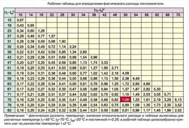
Calculation of the flow rate of the coolant (water) in the heating system
Heat loss at home with and without insulation.
So, in order to choose the right pump, you should immediately pay attention to such a value as heat loss at home.The physical meaning of the connection between this concept and the pump is as follows. A certain amount of water heated to a certain temperature is constantly circulating through pipes in the heating system. The pump circulates. At the same time, the walls of the house constantly give off part of their heat to the environment - this is the heat loss of the house. It is necessary to find out what is the minimum amount of water that the pump must pump through the heating system with a certain temperature, that is, with a certain amount of heat energy, so that this energy is enough to compensate for heat losses.
In fact, when solving this problem, the throughput of the pump, or water flow, is considered. However, this parameter has a slightly different name for the simple reason that it depends not only on the pump itself, but also on the temperature of the coolant in the heating system, and in addition, on the throughput of the pipes.
Taking into account all of the above, it becomes clear that before the main calculation of the coolant, it is necessary to calculate the heat losses of the house. Thus, the calculation plan will be as follows:
- finding heat losses at home;
- establishment of the average temperature of the coolant (water);
- calculation of the coolant in relation to the water temperature relative to the heat losses of the house.
How to calculate the consumed heat energy
If a heat meter is absent for one reason or another, then the following formula must be used to calculate heat energy:
Let's see what these conventions mean.
1. V denotes the amount of hot water consumed, which can be calculated either in cubic meters or in tons.
2. T1 is the temperature indicator of the hottest water (traditionally measured in the usual degrees Celsius). In this case, it is preferable to use exactly the temperature that is observed at a certain operating pressure. By the way, the indicator even has a special name - this is enthalpy. But if the required sensor is absent, then the temperature regime that is extremely close to this enthalpy can be taken as a basis. In most cases, the average is about 60-65 degrees.
3. T2 in the above formula also denotes the temperature, but already of cold water. Due to the fact that it is quite difficult to penetrate the main line with cold water, constant values are used as this value, which can vary depending on the climatic conditions on the street. So, in winter, when the heating season is in full swing, this figure is 5 degrees, and in summer, when the heating is off, 15 degrees.
4. As for 1000, this is the standard coefficient used in the formula in order to get the result already in giga calories. It will be more accurate than using calories.
5. Finally, Q is the total heat energy.
As you can see, there is nothing complicated here, so we move on. If the heating circuit is of a closed type (and this is more convenient from an operational point of view), then the calculations must be made in a slightly different way. The formula that should be used for a building with a closed heating system should already look like this:
Now, respectively, to decryption.
1. V1 denotes the flow rate of the working fluid in the supply pipeline (not only water, but also steam can act as a source of thermal energy, which is typical).
2. V2 is the flow rate of the working fluid in the "return" line.
3. T is an indicator of the temperature of a cold liquid.
4. Т1 - water temperature in the supply pipeline.
5. T2 - temperature indicator, which is observed at the exit.
6. And finally, Q is the same amount of heat energy.
It is also worth noting that the calculation of Gcal for heating in this case from several designations:
- thermal energy that entered the system (measured in calories);
- temperature indicator during the removal of the working fluid through the "return" pipeline.
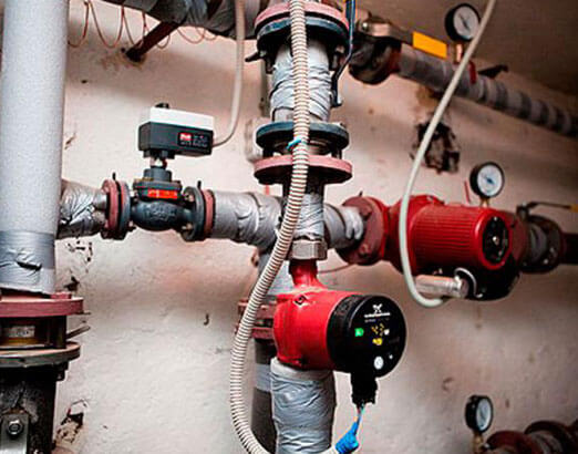
Selection of a circulation pump
Circulation pump installation diagram.
A circulation pump is an element, without which it is even difficult to imagine any heating system, is selected according to two main criteria, that is, two parameters:
- Q is the flow rate of the heating medium in the heating system. Expressed consumption in cubic meters for 1 hour;
- H is the head, which is expressed in meters.
For example, Q to denote the flow rate of the coolant in the heating system is used in many technical articles and some regulatory documents. The same letter is used by some manufacturers of circulation pumps to indicate the same flow rate. But factories for the production of valves use the letter "G" as a designation for the flow rate of the coolant in the heating system.
It should be noted that the designations given in some technical documentation may not coincide.
It should be noted right away that in our calculations the letter "Q" will be used to indicate the flow rate.
Translation of the result to normal form
It is worth noting that in practice you will not find such water consumption anywhere. All water pump manufacturers express pump capacity in cubic meters per hour.
Some changes should be made, remembering the course of school physics. So, 1 kg of water, that is, a heat carrier, is 1 cubic meter. dm of water. To find out how much one cubic meter of coolant weighs, you need to find out how many cubic decimeters are in one cubic meter.
Using some simple calculations or simply using tabular data, we get that one cubic meter contains 1000 cubic decimeters. This means that one cubic meter of the coolant will have a mass of 1000 kg.
Then, in one second, it is required to pump water with a volume of 2.4 / 1000 = 0.0024 cubic meters. m.
Now it remains to convert seconds to hours. Knowing that in one hour there are 3600 seconds, we get that in one hour the pump must pump 0.0024 * 3600 = 8.64 cubic meters / h.
Other methods of calculating the amount of heat
It is possible to calculate the amount of heat entering the heating system in other ways.
The calculation formula for heating in this case may differ slightly from the above and have two options:
- Q = ((V1 * (T1 - T2)) + (V1 - V2) * (T2 - T)) / 1000.
- Q = ((V2 * (T1 - T2)) + (V1 - V2) * (T1 - T)) / 1000.
All variable values in these formulas are the same as before.
Based on this, it is safe to say that the calculation of kilowatts of heating can be done on your own. However, do not forget about consulting with special organizations responsible for supplying heat to dwellings, since their principles and settlement system can be completely different and consist of a completely different set of measures.
Having decided to design a so-called "warm floor" system in a private house, you need to be prepared for the fact that the procedure for calculating the amount of heat will be much more complicated, since in this case you should take into account not only the features of the heating circuit, but also provide for the parameters of the electrical network, from which and the floor will be heated. At the same time, the organizations responsible for control over such installation work will be completely different.
Many owners often face the problem of converting the required number of kilocalories to kilowatts, which is caused by the use of measurement units in many auxiliary aids in the international system called "C". Here you need to remember that the coefficient converting kilocalories to kilowatts will be 850, that is, in simpler terms, 1 kW is 850 kcal. This calculation procedure is much easier, since it will not be difficult to calculate the required amount of giga calories - the prefix "giga" means "million", therefore, 1 giga calorie is 1 million calories.
In order to avoid errors in calculations, it is important to remember that absolutely all modern heat meters have some error, while often within acceptable limits. The calculation of such an error can also be performed independently using the following formula: R = (V1 - V2) / (V1 + V2) * 100, where R is the error of the general house heating meter
V1 and V2 are the parameters of the water flow in the system already mentioned above, and 100 is the coefficient responsible for converting the obtained value into percent. In accordance with operational standards, the maximum permissible error can be 2%, but usually this figure in modern devices does not exceed 1%.
Requirements for heat devices in an apartment building
The design of the heat meter should include:
- calculator;
- sensors that measure temperature, flow, pressure.
It is allowed to use devices that allow automatic remote transmission of data.
The consumer or supplier may, at their own request, install equipment for taking readings and monitoring resource use. Such devices should not compromise the accuracy of measurements.
The pressure in the pipeline can also be measured with a pressure gauge. But quality control of heat supply is impracticable without special means of measuring and storing results. Based on the readings from the pressure gauge, it will not be possible to make a valid claim to the service provider.
The heat meter must be reliably protected by seals against possible changes in its settings in order to falsify the measurement results. Setting the time on the clock inside is permissible only without breaking the seal. The calculator of the device must be equipped with a non-erasable archive that allows displaying its characteristics and settings on the counter or computer screen.
Modern meters make calculations of heat energy based on integral algorithms, using the measured current values of the coolant parameters for short periods of time (Methodology, formulas 3.1-3.3, 3.8, 4.1, 4.2, 5.1-5.5, 5.9-5.12, 11.1, 11.2).
All about heating meters, as well as about refusal from the central heating system in the apartment building, read here.
How to make a calculation
When choosing a pump, you need to know how much heat the house gives off to the environment. What's the connection? The fact is that the coolant, heated to a certain temperature regime, circulating through the system, constantly gives off some of the heat to the outer walls. This is the heat loss of home ownership.
The pump helps to circulate fluid in the required mode through pipes and radiators. It is necessary to find out the minimum of the coolant that the pump will pump. Everything is interconnected: the amount of coolant - heat energy - the work of the circulation pump. If the heat energy is not enough to compensate for the heat loss, then the system will be ineffective.
It turns out that in order to solve the problem, you need to find out the throughput that the pump can "pull". In other words, it is necessary to calculate the flow rate of the coolant.
But this parameter has a different name, since, in addition to the pump, it also depends on two factors: the degree of heating of the coolant and the throughput of the water circuit.
Thus, in order to calculate the flow rate of the coolant in the heating system, they find out the heat losses of home ownership.
Calculation stages:
- find heat losses at home;
- find out the average temperature of the coolant;
- make a calculation of the flow rate of the heat carrier by the heat load, where heat loss is taken into account.
On a note. The circulation pump consumes little electrical energy. There is no need to be afraid of unnecessary financial expenses. Even a less powerful UPS will help you wait out several hours without electricity in an emergency. And if a modern boiler with electronics is paired with a pump, then you don't have to worry about power outages.