The purposefulness of the installation of the collector system
But it is impossible to install a collector heating system in an apartment of old multi-storey buildings, because a tee heating system already works there. For the collector system to work, it is necessary to close the hydraulic circuit, which is necessary to create a circulation of the coolant in the system. If a closed hydraulic circuit is created in one apartment, the other apartments will be cut off from the heating system.
The collector heating system also cannot be used in areas with an unstable power supply, since when the circulation pump stops, the water will freeze and the pipes will fail. But the situation can be somewhat improved by using
Filling the system with coolant
To put the device into operation, fill all circuits with hot water. To test the functionality, it is sufficient to compare the pressure parameters. In case of discrepancies, it is necessary to check the correct installation of all components in order to prevent equipment failure. The valves are opened alternately. Work with one contour first. In this case, the valves of the non-working sections must be in the closed position.
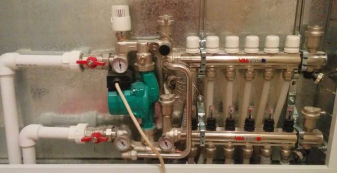
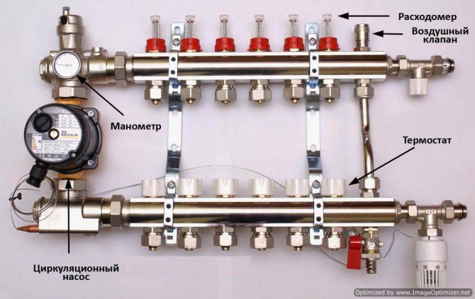
When operating the underfloor heating system, provide access to the flow meter flask. The indicators of this equipment may be needed when repairing or maintaining the system. Install one flow meter for each individual circuit. This way you can increase control over all processes in the system.
When choosing a model, try to pay attention to reputable manufacturers. High-quality equipment includes all the necessary components, so you do not have to spend additional funds.
For all questions, please contact our specialists!
Collector heating system. The principles of its work.
How to install a mixing unit for a warm floor with your own hands
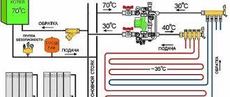
As I said earlier, this type of heating system is most often used in two or more storey buildings. But no one will forbid you to use it in a one-story house. It all depends on expediency. In addition to heating devices, an indirect heating boiler or a pool or greenhouse heating system can be connected to the manifold. So this kind of trick can be used in a one-story house. The main thing is not to forget that in the collector heating system there can only be forced circulation of the coolant. This means that it must have at least one, and most often several circulation pumps. We look at the picture below:
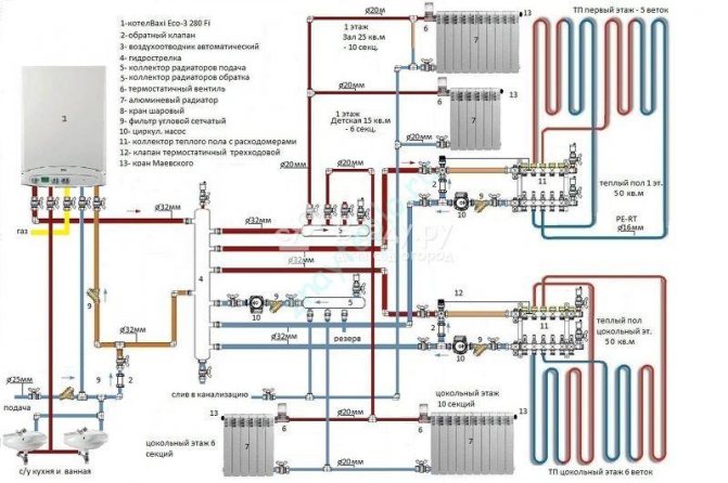
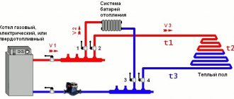
The figure shows a diagram without an indirect heating boiler. This is done here because a double-circuit gas boiler is used. Well, if the boiler is single-circuit, then everything will look a little different:
It has everything modern homeowners love:
- Radiators.
- Water heated floors.
- Reserve electric boiler.
- Indirect heating boiler.
If you do not count together with the boiler pump, then there will be 5 of them. In order for the circulation pumps not to create a pressure difference between the “supply” and “return” collectors, a hydraulic arrow is used here. Thanks to it, the boiler circulation pump can always provide the required flow rate of the heat carrier through the boiler heat exchanger, which has a positive effect on its service life. The underfloor heating circuits are connected through their collectors with autonomous circulation groups. Here you need to take into account the possibility of an emergency power outage.To ensure the operation of the "brain" of the boiler and circulation pumps during shutdown, you will need. Without it, the circulation of the coolant in the system will stop, and this is fraught with all sorts of unpleasant consequences.
The main advantage of such a heating scheme is the ability to turn off individual branches without stopping the entire system. This feature helps a lot when an emergency repair is needed. Well, the disadvantage will, perhaps, be the price of all this pleasure. Although, if you do for yourself and for a long time, then it makes sense to do everything according to your mind. Otherwise, your stinginess will make you pay twice! On this optimistic note, I will end this post, waiting for your questions and likes on social media!
Self-assembly guidelines
If a decision is made to make a collector for a warm floor with your own hands, it is imperative to provide an air relief valve. Other design and adjustment elements may be as follows:
- flowmeters that require a certain size of taps with threaded connections can be replaced with shut-off valves. A simple valve that regulates the flow is quite effective;
- in order to set a constant heat supply, it is recommended to use a three-way valve. Its configuration will be fine enough, but after its completion, the system will not require intervention for a long time.
When placing a self-made collector in a wall cabinet or other places with limited space, there should be enough space for the circulation pump. In addition, it will be necessary to provide a power supply and convenient access to the adjustment points.
To improve the performance of a self-made manifold, a three-way valve with a thermal head can be used. The adjustment of such a unit is as simple as possible. Sophisticated thermal head models can receive a signal from external sensors, for example, located outside the building.
Regardless of whether a ready-made collector solution is used or it is assembled independently - a floor heating system equipped with such a unit will work efficiently and reliably. Therefore, when planning to get a good microclimate and the possibility of changing it in each room, you should carefully study the market offers.
Do-it-yourself budget version of the collector:
Better yet, get expert advice or entrust the development of a heating system to professionals.
Setting up the underfloor heating collector is a demanding task, on which the efficiency of using the system depends. The liquid heat transfer agent is economical and efficient in use. Many private home owners choose warm water floors as an additional heating method.
Despite the high performance, such structures are very demanding in terms of installation and operation technology. To complete the work, various auxiliary equipment and equipment are required. Adjusting the underfloor heating manifold with flow meters is the most important process that you must be able to cope with before installing a heating system in your home.
Electromagnetic flowmeters
Connecting a warm floor to a thermostat thermostat
Their principle of operation is based on the law of electromagnetic induction, according to which an EMF is induced in an electrically conductive liquid passing through an electromagnetic field, which is proportional to the speed of the flow (conductor).
Such flow meters have found application in volumetric metering systems for heat carrier and water at industrial and power plants. The disadvantage is the high cost and weight for diameters of more than 300-400 mm, the complexity of removal for verification.
Rod electromagnetic water meters operate on the principle of immersing the sensor in a liquid, where the flow rate is measured. Such meters determine the flow of cold water in completely filled pipelines.
Flowmeter installation principles
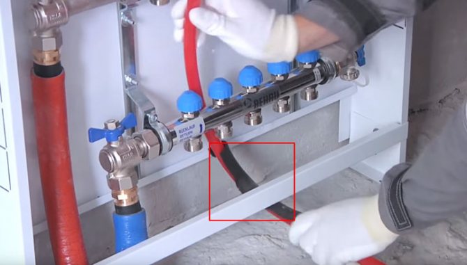
The flow meter is connected by connecting the manifold and heating circuits. For the correct execution of the task, the equipment should be fixed on a special comb, to which the spent coolant flows. When the required surface temperature is reached inside the collector, a valve is triggered, which blocks access to water.
Setting up underfloor heating with flow meters requires the use of a thermostat. It is necessary to optimize performance and conformity to a given scheme. When installing all the elements, it is worth adhering to the utmost compactness in order to prevent further functioning problems.
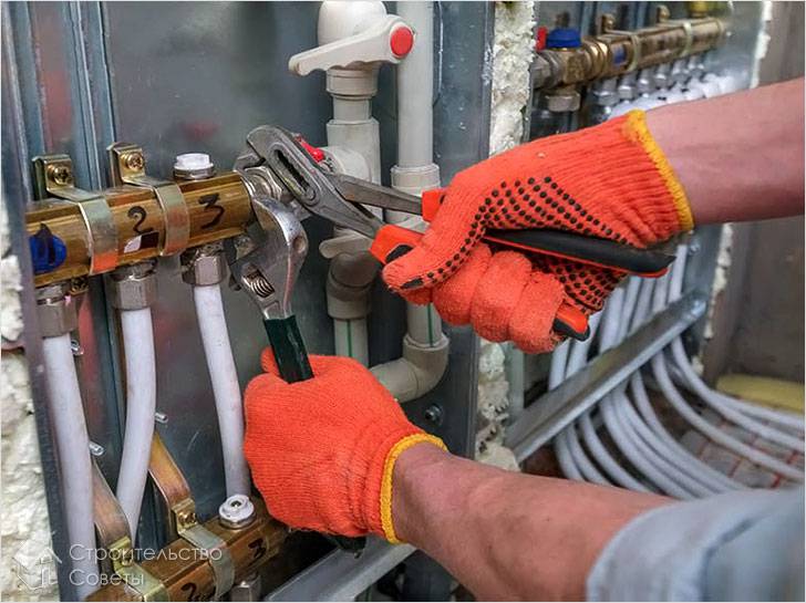
Proceed with the installation in the following sequence:
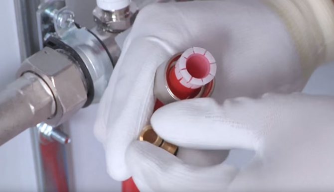
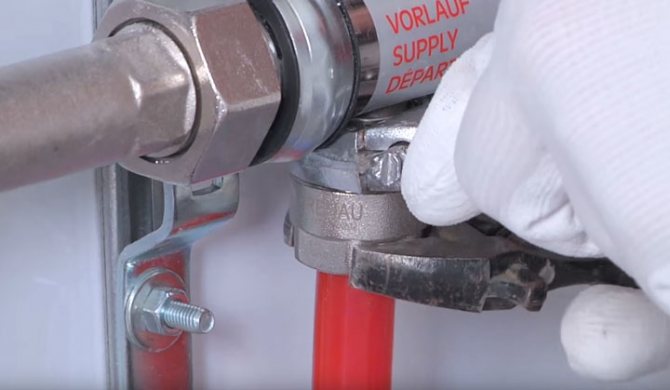
- screwing the flow meter into the technical opening of the installation using a wrench of the required size;
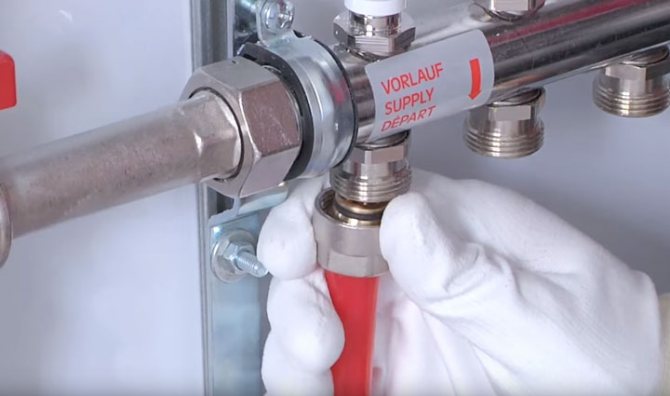
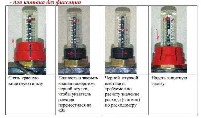
- preparation of equipment for operation (this requires turning the flask counterclockwise);
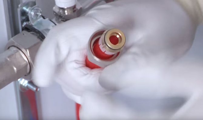
- dismantling the fuse installed by the manufacturer;
- setting the required pressure by turning the brass ring clockwise;
- place a special overlay on the ring in order to prevent mechanical vibrations;
- test the functioning of the entire structure.
Before proceeding with the direct installation, you should make sure that you have all the necessary tools and accessories.
Selection, installation and adjustment of flow meters
Which electric boiler for a warm floor is better to choose
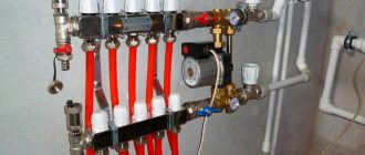
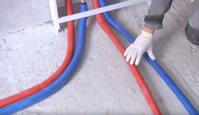
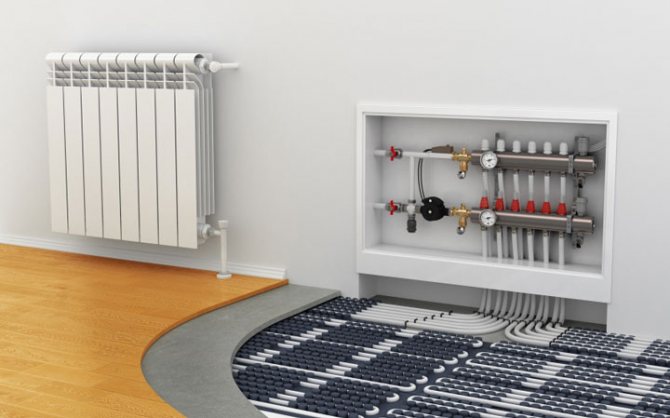
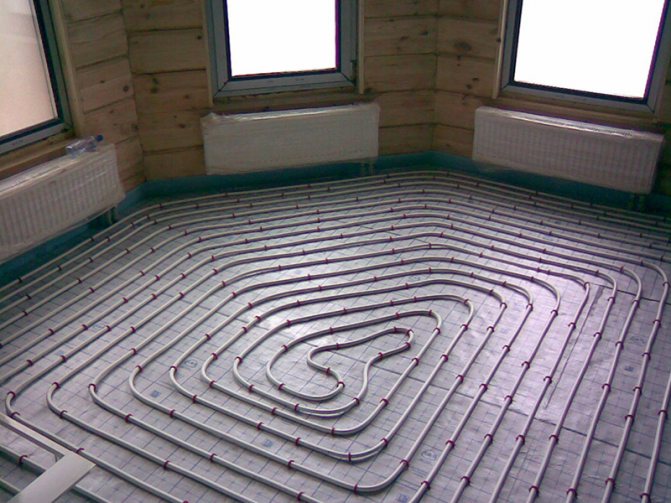
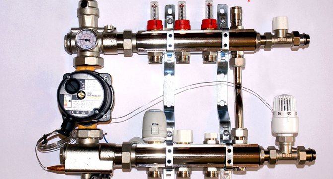
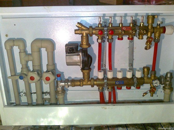
A water heat-insulated floor, as a rule, consists of several circuits of plastic pipes. Hot water, moving through them, gives off its heat and returns through the return supply part of the system. The collector (comb system) of a warm water floor is designed to collect cooled water, mix and supply heated water. In other words, it is a unit that controls the operation of the underfloor heating system.
To regulate the temperature, flow meters are provided in the manifold. These devices control the flow rate of the coolant, in this case water.
Why do you need a flow meter
Theoretically, it is quite possible to do without installation in the manifold of the flow meter. However, if you do not install this device, then:
- In different rooms, the temperature will be different;
- Excessive consumption of electricity for heating water in the system is possible;
- Different circuits will heat up unevenly.
A simple example would be a bathroom and a bedroom. A gas or electric boiler heats water in the same way for the bath and for the bedroom. But the bathroom is at least 3 times smaller than the bedroom.
Accordingly, it will be hot in the bathroom and cool in the bedroom with the same water supply to the underfloor heating system. This situation is due to the fact that the total length of the plastic pipes in the area is much larger in the bedroom.
It is in order to regulate a comfortable temperature regime in the entire apartment that the installation of such a device is desirable.
Advice! When installing a water-heated floor, you need to strive to make the contours of pipes of approximately the same length. This will save energy costs and allow more accurate temperature control.
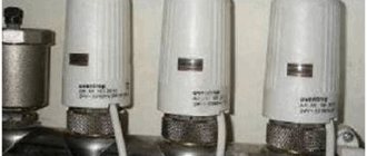
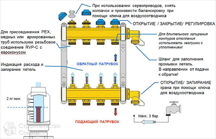
Principle of operation
The device is installed on the return collector taps. When a predetermined temperature is reached in the manifold valve system, the lumen of the energy carrier is narrowed or completely closed. This principle of operation is possible with full automation of the system. For this, the collector is equipped with a temperature sensor.
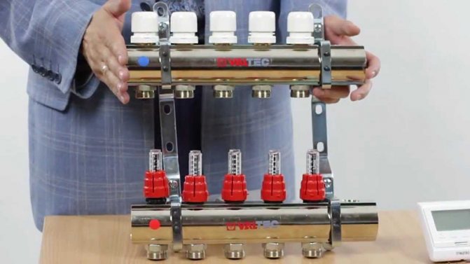
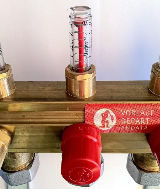
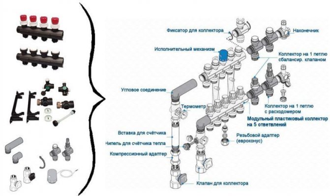
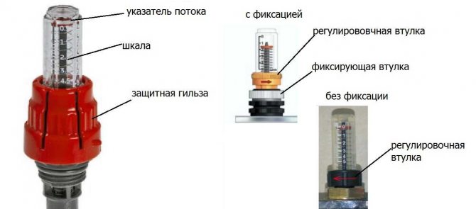
The flowmeter itself consists of several parts:
- Housing;
- Transparent flask with a scale;
- Float.
The flask is usually made of durable glass, the body can be plastic or brass. The float is located inside the flask, it serves as an indicator of the speed of the coolant. The flowmeter is also called a float flowmeter.
In the automatic collector of a water heated floor, the balancing of the coolant flow is carried out using a temperature sensor.If the latter is not provided, then the flowmeter can be adjusted manually.
Step-by-step instructions for installation and adjustment
H2_2
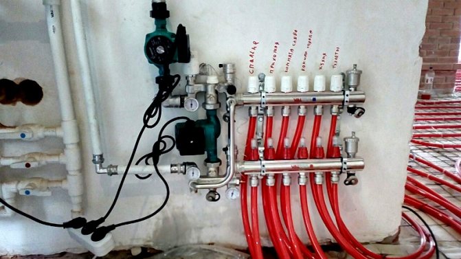
The rotameter is installed strictly vertically. To ensure that the liquid level in the flask is accurate, the collector itself is also mounted according to the level. If the manifold line is installed crookedly, the temperature control will be incorrect.
Since finishing works often take place after the installation of the collector, it is necessary to protect the unit and its components from possible damage. The best option is to make a niche in the wall for it or a special cabinet.
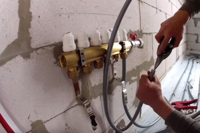
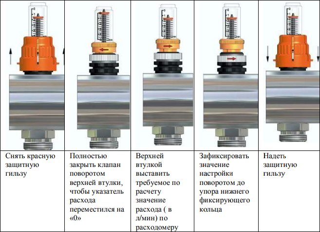
Installation and adjustment:
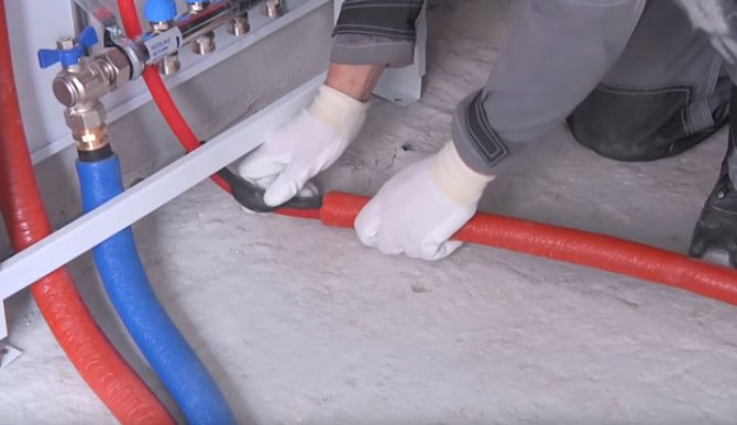
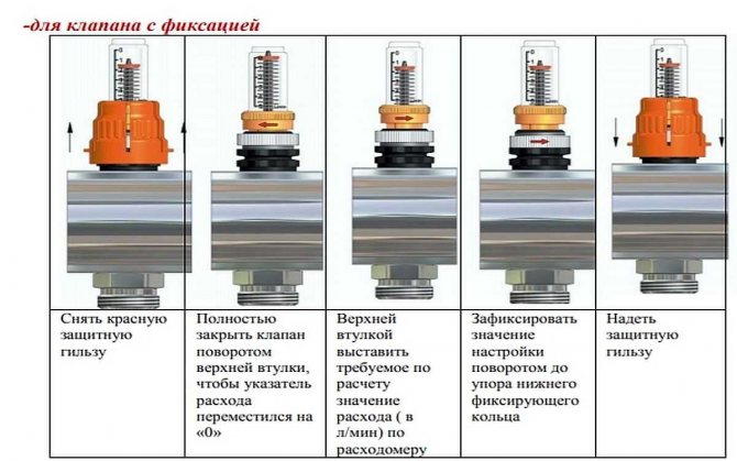
- Using a wrench, screw the flow meter into the process inlet of the collector return line;
- Turning the membrane (flask) counterclockwise, open the pressure meter;
- Remove the factory protective ring;
- Turn the brass body ring clockwise to the desired head. This is balancing the flow rate of an energy carrier. The float on the scale will indicate the set value;
- Close the brass ring with a cover plate. This must be done to avoid damage to the device, especially if the water underfloor heating unit is not closed in a niche or cabinet;
- Check system operation.
During operation of the assembly, the bulb remains open so that the level of the water float can be seen. If balancing is needed during operation, the diaphragm simply turns in the desired direction.
Choosing a flow meter for a water-heated floor
High-quality variable area flowmeters must be accompanied by a guarantee for 5-7 years of stable operation. It is recommended to select flowmeters with a brass body
You should also pay attention to the flask, it should be made of transparent glass with good visibility of the water level scale. However, there is an opinion that it is better to choose products with a membrane made of impact-resistant plastic.
When choosing a device, you need to take into account the area of the pipeline system
It is also important whether the node is automated or not. In the first case, balancing will be extremely rare, mechanized collectors require more attention.
Features of the flowmeter functioning
The basis of the equipment is a plastic case with a special float inside. The composition also includes a transparent flask with a marking scale. Depending on the movement of the float, the amount of coolant inside the system is estimated. By analyzing the indicators, you can make a decision about switching modes.
Water flow meter for underfloor heating is an auxiliary device in the work of the structure. From a theoretical point of view, the user can do without this equipment. But it should be borne in mind that the absence of measuring equipment significantly complicates the control over the functioning parameters. In some cases, this can even lead to failure.
The regulation of the flow meters on the underfloor heating collector ensures an even distribution of heat. In the absence of a device, there is a possibility that the surface temperature will be different in different rooms. You also run the risk of exceeding the flow rate for the coolant. Such restrictions are due to the difference between the sizes of the rooms. The underfloor heating flow meter creates conditions for maintaining optimal temperatures based on the dimensions of the room.
The device is able to work autonomously without the need for a power source. It reduces energy costs and optimizes system performance. The equipment is unpretentious in maintenance and installation. The case should be placed in an upright position, otherwise you run the risk of encountering various operational problems. In conclusion of the analysis of this apparatus, it can be concluded that it is impractical to abandon the regulating device.
Manual adjustment of the heating agent temperature

Temperature control methods will depend entirely on the equipment used.For example, if a system with a temperature controller and a servo drive is installed, then the setting is carried out according to the instructions from the manufacturer of this device. In this case, the adjustment is carried out in automatic mode. Now we will consider a manual method of setting the temperature using thermal heads.
Installation of thermal heads can be performed both for the supply and return of the coolant.
First of all, the system to the warm floor must be completely filled with coolant and free from air
But here it is important not to rush, otherwise air jams may form. If the connection was made from the boiler, then before starting the water into the heating circuits, turn off all the taps
After that, open the supply / return on one loop, filling it with a coolant. The air from it must escape through the air vent. Now turn on the circulation pump so that the coolant begins to move in this loop. At the same time, turn on the temperature on the boiler to 35 °. By touch, you should feel that hot water has flowed on the return and supply in the heating circuit. If everything is working properly, close this loop and open a new one. Using this method, you pump in and check each loop of the heating circuit. When you have set up each circuit, you open all the taps and adjust the required temperature by touch. In some hinges, the tap will need to be opened completely, while in others it is enough to slightly open it.
The coolant temperature in each circuit can be different. There are several reasons for this, such as the length of the loop. The shorter the contour, the faster it warms up and vice versa.
Thus, manual temperature control is carried out. It is enough to perform it once a year. But here it is important to take into account the nuance. The underfloor heating system is inertial. What does this mean in practice? If you have made changes to one of the hinges, you will have to wait a few hours to feel the clear changes in the indoor temperature.
If you have installed flow meters on the manifold, then the difference between the readings can reach up to 0.5 liters.

The technical component of the additional heating system
The functioning of the system is carried out using a number of equipment:
- collector installation;
- special valve;
- pump for the circulation of the coolant.
The flowmeter is used to control the process of distribution of the coolant. This element of the system is fundamental to the functioning of the pumping system. The collector performs the function of supplying hot coolant with subsequent intake and direction to the central unit. Waste and hot water is mixed in a special unit. This feature allows you to achieve high productivity and rationality of operation.
Rotameters and safety valves regulate the temperature in the respective areas of the warm floor. The equipment prepares exactly the volume of water that is required to heat a specific area. The device monitors the amount of coolant in various circuits, ensuring the coordinated work of all components.
When installing water floors, make sure that all contours are the same length, despite the difference in configurations. Thus, you can achieve optimal heat distribution in the room and reduce energy losses.
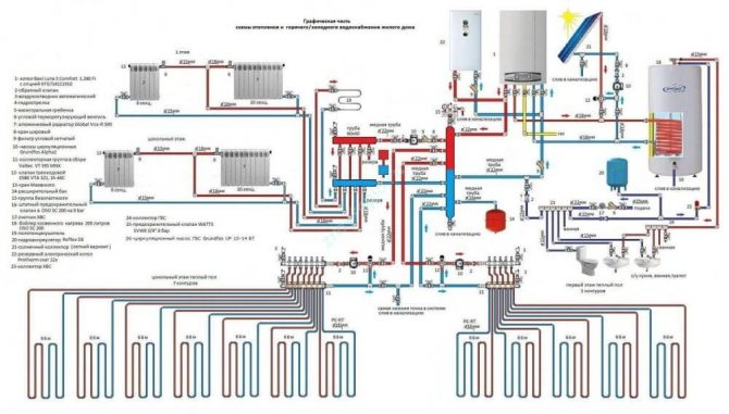
Combined heating scheme VALTEC
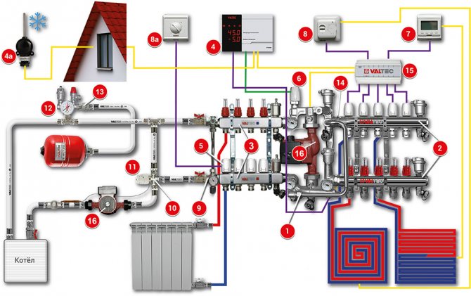
We would like to draw your attention to an example of a modern energy efficient heating system based on VALTEC equipment. It is designed for a country house or any other object with an autonomous heat source (boiler, etc.). The scheme provides for the combined use of traditional radiators and underfloor heating. This combination of technologies, as well as the applied automation make it possible to provide a high level of comfort at optimal costs for the purchase of equipment and its operation. The diagram uses and displays components from the current VALTEC assortment.
| № | vendor code | Name | Manufacturer |
| 1 | VT.COMBI.S | Pump-mixing unit | VALTEC |
| 2 | VTC.596EMNX | Collector block with flow meters | VALTEC |
| 3 | VTC.586EMNX | Collector block made of stainless steel become | VALTEC |
| 4 | VT.K200.M | Weather-compensated controller | VALTEC |
| 4a | VT.K200.M | Outside temperature sensor | VALTEC |
| 5 | VT.TE3040 | Electrothermal servo drive | VALTEC |
| 6 | VT.TE3061 | Analog servo | VALTEC |
| 7 | VT.AC709 | Electronic room chronothermostat with floor temperature sensor | VALTEC |
| 8a | VT.AC601 | Room thermostat | VALTEC |
| 8 | VT.AC602 | Room thermostat with underfloor heating sensor | VALTEC |
| 9 | VT.0667T | Bypass with by-pass valve for circulating with closed loops | VALTEC |
| 10 | VT.MR03 | Three-way mixing valve for maintaining the return temperature | VALTEC |
| 11 | VT.5012 | Thermal head with remote attachment sensor | VALTEC |
| 12 | VT.460 | Security group | VALTEC |
| 13 | VT.538 | Squeegee-cutter | VALTEC |
| 14 | VT.0606 | Double manifold nipple | VALTEC |
| 15 | VT.ZC6 | Communicator | VALTEC |
| 16 | VT.VRS | Circulation pump | VALTEC |
Explanations for the diagram:
The use of the VALTEC COMBIMIX pump-mixing unit allows to link high-temperature circuits (heat source and radiator heating) and underfloor heating circuits with a low coolant temperature into a single system.
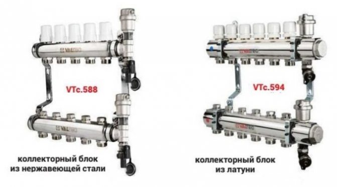
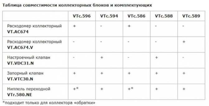
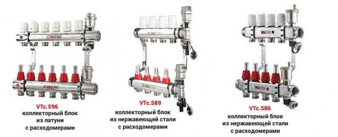
The distribution of coolant flows is organized using VALTEC VTc 594 (radiator heating) and VTc 596 (floor heating) manifold blocks.
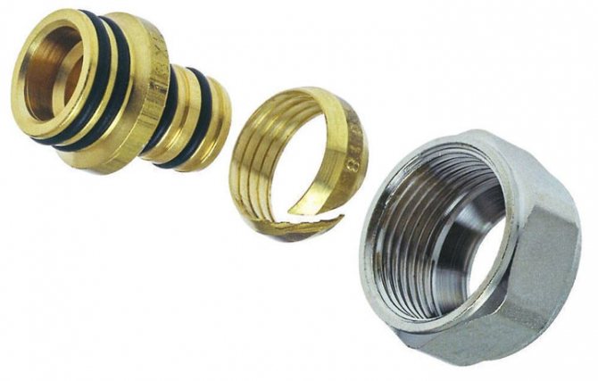
The distribution of the high-temperature heating system and the heating circuits are made of VALTEC metal-plastic pipes. The pipelines were installed using press fittings of the VTm 200 series; connection to manifolds - compression manifold fittings for metal-plastic pipes VT 4420.
Underfloor heating operation is controlled by a VALTEC K100 controller with a weather compensation function. Due to this, the temperature of the water in the underfloor heating circuits changes depending on the outside temperature, which guarantees savings in energy resources used for heating. The control signal from the controller is fed to the analog electrothermal servo drive of the control valve of the COMBIMIX assembly.
Thermal comfort in rooms with underfloor heating is maintained by a room thermostat VT AC 602 and a chronothermostat VT AC 709, equipped with air and floor temperature sensors. Through electrothermal drives, these automation modules control valves on the return manifold of the VTc 596 unit.
A thermostat with a remote temperature sensor VT AC 6161 is used as a safety thermostat. It stops the circulation pump of the COMBIMIX unit in case of exceeding the set maximum temperature of the heating agent in the supply to the underfloor heating circuits.
The heat transfer of the radiators is regulated by the room thermostat VT AC 601, which controls the valves of the VTc 594 manifold block using electrothermal servo drives.
The heat source circuit is equipped with a boiler safety group, a diaphragm expansion vessel, VALTEC non-return and drain valves.
Ball valves of the VALTEC BASE series were used as shut-off valves.
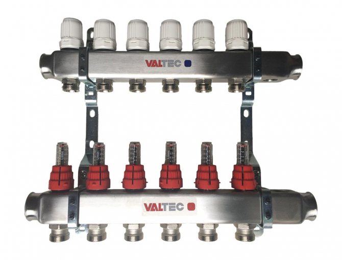
Valtec underfloor heating collector for 2-4 circuits 20-60 sq.m.
Maximum heated floor area: 60 sq.m; Manual regulation. (For automatic regulation, it is required to additionally install a servo drive VT.M106.0.230 and a control thermostat or controller)
Specification
- 1 - Mixing valve MIX 03 3/4 "- 1 piece;
- 2 - Nipple adapter 1-3 / 4 "(VTr.580.N.0605) - 2 pcs;
- 3 - nipple 3/4 "(VTr.582.N.0005) - 1 piece;
- 4 - tee 3/4 "vn.-vn.-vn. (VTr.130.N.0005) - 1 pc;
- 5 - knee 3/4 "Nar.-Nar. (VTr.093.N.0005) - 1 pc;
- 6 - American 3/4 "(VTr.341.N.0005) - 1 piece;
- 7 - circulation pump with 1 "union nuts;
- 8 - ball valve 3/4 "vn.-vn. (VT.217.N.05) - 2 pcs;
- 9 - collector 3 / 4-1 / 2 "planks. (VTc.500.N.0502) - 2 pcs;
- 10 - collector connector 16-1 / 2 "(VTc.710.N.1604) - 4 pcs;
- 11 - connector with ext. threads. 20-3 / 4 "(VTm.302.N.002005) - 1 piece;
- 12 - connector with plank beds. threads. 20-3 / 4 "(VTm.301.N.002005) - 1 piece;
- 13 - collector tee (VTc.530.N.0500) - 2 pcs;
- 14 - automatic air vent 3/8 "(VT.502) - 2 pcs;
- 15 - drain valve 1/2 "(VT.430) - 2 pcs;
Connection
With the help of connectors (10), a 16x2 metal-plastic underfloor heating pipe is connected.The high-temperature circuit supply (boiler supply) is connected to terminal 16, and the boiler return is connected to terminal 17.
Valtec underfloor heating manifold with manual adjustment for 2 circuits. The hinges should be of approximately equal length for proper functioning. At the entrance and exit to the heating system 16, 17, it is advisable to mount American taps.
If 3 or 4 circuits are used in the above mixing unit for underfloor heating, then two collectors (9) are replaced by one variable collector (VTc.560n) and one collector with ball valves (VTc.580n).
Problems that may arise
Let's give a concrete example.
Difficulties in the installation of the system
The length of the contours in rooms of different sizes is different. This creates problems.
- The contour of the warm floor is installed in the bathroom, living room and kitchen.
- It connects to one collector.
- It is clear that the floor area in these rooms is different. Consequently, the length of the pipelines laid under the coating is also different.
- This means that the consumption of the coolant in them will also be different.
Note! In short heating rings, the level of hydraulic resistance of the tubes is lower. Based on this, water circulates in them faster than in long counterparts.
Therefore, at the same temperature of the liquid on the supply manifold, the floor will be overheated in some rooms, while in others it will remain cold.
The same situation can arise when using radiator heating circuits with a different number of sections and different pipe lengths, which are connected to the same storey collector. That is, some rooms will be overheated, while others will be cold.
To prevent this from happening, the instruction recommends determining the water consumption in the radiator system by installing a thermostat on each battery. In fact, it is a valve that quantitatively controls the flow. Roughly the same can be done on an underfloor heating system.
Ways to solve the problem
It is possible to balance the heating circuits of underfloor heating systems that are connected to the same collector group in two ways.
- Applying the first of them, you need to make all the rings of equal length and correctly distribute them under the cover. For example, three circuits will be in the guest room, two in the kitchen and one in the bathroom.
- The second way is to mount only 3 circuits, according to the number of rooms. However, they will need to be connected not directly to the collectors, but through special devices - flow meters for underfloor heating, they are also called rotameters. By design, they are balancing valves.
In the given example, the term "flow meter" does not mean a measuring device, but a special tap, with which it is possible to control and set the consumption of the heat carrier.
It should be borne in mind that devices from some manufacturers can only be connected to a return manifold.
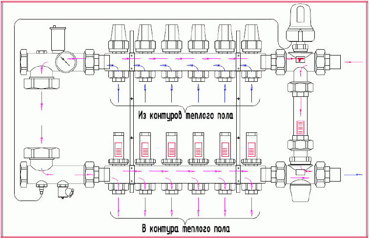
Optimal design of the manifold group.
- The best option, when the manifold assembly has such a design, is that the supply manifold is equipped with a rotameter, and a thermostat is placed on the reverse analogue.
- Due to this, the supply part of the group directs a precisely metered volume of the heat carrier into each of the heating circuits. The return collector closes, opens the circuits, as the liquid cools down in the pipes.
- In addition, it is desirable that the supply manifold for underfloor heating with flow meters has an automatic air vent and is connected to the return analogue bypass having a bypass valve.
Note! Air that interferes with its operation is removed from the heating system through a vent. When it gets warmer outside, the thermostats close the circuits, at this time the bypass valve turns on and lowers the jumped pressure.
At the moment, manufacturers produce many flow meters, which are both measuring devices and regulators of the flow rate of the heat carrier. There are also devices that combine these functions. Naturally, their price is higher.
If you purchase only a measuring device, it will need to be installed together with an ordinary valve. By opening or closing the tap, according to the readings of the rotameter scale, you will be able to regulate the flow of the coolant.
How to balance heating circuits
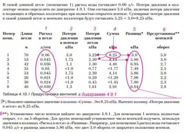
An example of balancing a system.
- The total flow of the coolant through the collector (l / min) is taken as 100 percent.
- Further (also as a percentage), the consumption for each of the circuits is determined. For example - 15%, 35% and 50%. They are converted (proportionally) to liters per minute.
- Then you need to unscrew or twist the head of the rotameter (or the valve connected to the measuring flow meter), thereby setting the required readings.
- It should be borne in mind that only calculated balancing of the circuits can be carried out in this way.
Assembling the manifold with flow meters.
- The actual adjustment is made according to the real flow rate of the coolant. For this purpose, a measuring rotameter must be installed in front of the supply part of the underfloor heating collector. Based on his readings, it will be possible to scatter the total costs along the circuits connected to the collector group.
Criterias of choice
The quality of the underfloor heating system depends on the correct selection of the flow meter. Three types of rotameters are produced:
- Measuring. This type of flow meter is installed with a manual control valve. The control is carried out taking into account the measuring indications.
- Regulatory. It performs only one function - control of the amount of heat transfer fluid entering the water circuits.
- Combined. Such a device combines two actions - adjustment and measurement. The cost of the product is much higher than that of models performing the same type of function.
When buying a flow meter for a warm floor, you should pay attention to the following product parameters:
- Body material. Devices made of brass have high wear resistance. From above, such a case should be plated with nickel. Plastic products are cheaper, but they have a lower strength index.
- The integrity of the device. Before purchasing a variable area flowmeter, it is recommended to carefully inspect the body and transparent flask in order to exclude the presence of cracks or other defects.
- Inner part. The spring in the middle of the meter body must be stainless steel.
- Flask. The transparent cap with a measuring scale in quality models is made of polycarbonate. Such material is quite strong and has high temperature resistance, which is especially important when used in heating systems.
- Specifications. In the instructions attached to the gauge, the temperature level is indicated. This indicator should be at least 110 degrees. Also no less important is the pressure - at least 10 bar.
- The maximum value of the throughput. The rotameter must be able to pass through itself at least 2-4 meters of coolant in an hour.
Underfloor heating flow meter
The manufacturer of the product should also be approached. The main indicator of the reliability of the product is the availability of a quality certificate and the provision of a guarantee, which the responsible companies provide for up to five years.
Time-pulse ultrasonic counters
The time-pulse method (or, in other words, the phase shift) is based on measuring the travel time of a signal against the flow and in the direction of fluid movement. To convert the ultrasonic signal, two or four piezoelectric elements displaced along the movement of water are installed on the pipeline. As a rule, disc elements are used, less often annular ones (for small diameters).
Piezoelectric elements can be installed inside the flow (on the inner walls of a pipe or channel) or outside the pipeline (in this case, the signal passes through the outer wall). Depending on the sensors used, the meters can be installed in gravity systems (both open and closed), as well as in completely closed pipelines with overpressure of the medium. There are such types of speed sensors:
- pipe - cut into the water supply from the outside. Can be used in pressurized and non-pressurized environments;
- wedge-shaped - installed on the bottom or inner wall of the pipe. As a rule, they are used in free-flow channels or in pipelines of large diameters, if installation and maintenance of the sensor from the outside is inconvenient;
- spherical or hemispherical - mounted on inclined walls of open trapezoidal channels;
- sucker-rod - have the form of tubes, are installed on the vertical walls of the channels;
- overhead - contactless sensors, placed on the outer surface of the pipeline.
Depending on how the sensors are installed, a distinction is made between contact and non-contact devices. The advantage of non-contact portable flowmeters is the ability to install them on pipelines without breaking the integrity. They are rarely installed permanently, more often they are used for verification measurements at different points.
Pulse time meters are suitable for finding the flow rate of clean water or slightly contaminated water (with a small amount of suspended solids). They are used in water supply and wastewater disposal, in cooling circuits, in irrigation irrigation schemes, at pumping stations, in open natural and artificial canals and rivers. They are used for both commercial and technological accounting.
Outcomes
It is important to ensure that when the underfloor heating system is operating, the flow rate on the manifold is visible. This is necessary for maintenance. Each water circuit must have its own flow meter.
We recommend: What are the characteristics of Caleo underfloor heating?
As you can see, in the equipment, each element performs its functions, therefore, each must be given sufficient attention, and in order for the entire system to work as a whole, it is worth equipping it with a flow meter and a collector, which will evenly distribute all the heat.
- Similar posts
- Rating of manufacturers of underfloor heating under tiles
- What are the advantages of Heat plus underfloor heating?
- How to install a warm floor with a snail?
- Can laminate flooring be laid on a warm floor?
- How to install a warm floor in the country?
- What should be the liquid for the warm floor?
Cross-correlation ultrasonic counters
These flowmeters work by the ultrasonic cross-correlation method. This technique is based on the principle of plotting velocities for different levels of flow, the meter makes it possible to build a real diagram of the distribution of velocities in the flow. The flow rate is also measured.
With water meters, ultrasonic tube and wedge-shaped velocity sensors are used, installed in the flow, the liquid level is determined using surface and underwater sensors. Execution of combined speed and level sensors is possible.
The meters are used in pressure and gravity, open and closed systems. It is an accurate measurement method that gives reliable results for streams of varying degrees of contamination, and it is also effective in inhomogeneous media. Flowmeters are used in technological pipelines, treatment plants, in rivers and reservoirs, etc. In large canals, several sensors can be installed across the entire width to obtain more accurate results.
How the heating collector works.
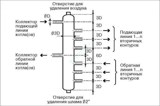
The most common horizontal balancing manifold is designed like this:
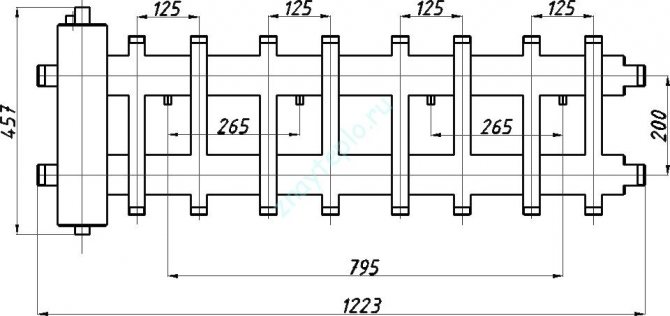
There are many different collector designs on the market today.The figure above shows a horizontal manifold with a hydraulic arrow, but there are vertical options for a similar design and it looks something like this:
The essence here is similar to that implemented in the vertical design. But there is a slight difference in the piping. Here to whom, what is more convenient it is necessary to look at the place. Such a collector can be made from a large diameter polypropylene pipe. In this case, it is advisable to maintain the proportions indicated in the figure.
If you are cramped in space, then there is another very interesting design. It can be called coaxial:

Here, two pipes are inserted into one another. In this case, the hydraulic arrow can only be connected separately.
Okay, let's talk about collectors, and now let's look at a heating system based on it. Moving on!
Doppler method
Meters using this method measure the difference in wavelength reflected from a moving stream relative to the wavelength of the emitted signal. Measurement of the received and transmitted signal to determine the difference between them is carried out using wedge-shaped or pipe velocity sensors installed at the bottom of the channel or pipe.
Doppler-based water meters are used in pressure and gravity systems, fully and partially filled pipes, open channels. They operate in streams of varying degrees of pollution (except for pure water). Doppler flow meters are used for commercial metering in pipelines and gravity canals, for measuring flow rates in rivers and canals of irrigation systems, in storm sewers, at pumping stations, pipelines for water intake and discharge into water bodies.