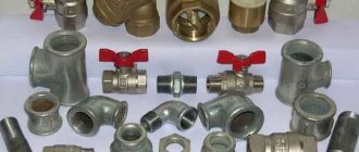
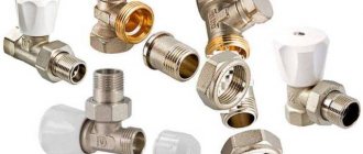
Valves are integral elements of any heating system (CO), regardless of the chosen scheme and configuration of the circuits. With the help of these simple devices, the heat supply parameters are adjusted, ensuring the safety and stability of the system. This publication will consider the main valves used in centralized and autonomous heating systems, their purpose, principle of operation and design features.
[contents]
Criterias of choice
The number and parameters of valves required for a specific CO is selected at the stage of calculations and design. The main criteria that affect the choice of these elements are:
- Type, scheme and configuration of CO.
- Temperature conditions (nominal and maximum).
- System pressure (working and maximum).
- Pipeline section and thread type.
- Coolant type (water, brines, antifreezes).
The operation of these devices stabilizes CO, makes it efficient and safe. Anyone who is engaged in self-installation of a heating system in a home needs to know the purpose and their principle of operation. All valves can be divided according to their purpose into three categories: safety, control and regulation group.
Everyone knows that any CO is an increased source of danger, since the coolant in the system is under pressure. And the higher the temperature, the higher the pressure (in closed CO). Next, consider the devices that are responsible for the safety of the CO
Safety
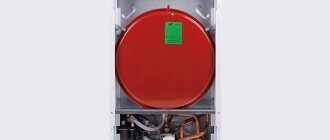
In most models of modern boilers, manufacturers provide a safety system, the "key figure" of which is the safety fittings included directly in the boiler heat exchanger or in its piping.
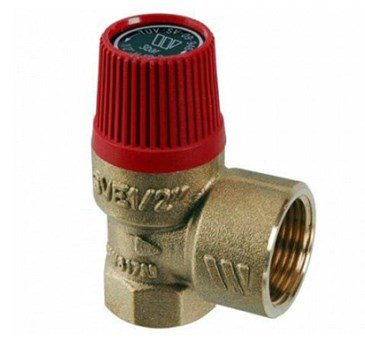
Appointment safety valve in the heating system consists in preventing the pressure rise in the system above the permissible level, which can lead to: destruction of pipes and their connections; leaks; explosion of boiler equipment
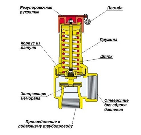
The design of this kind of fittings is simple and unpretentious. The device consists of a brass body, which houses a spring-loaded closing diaphragm connected to a stem. Spring resilience is the main factor that keeps the diaphragm in the locked position. The adjusting knob adjusts the compression force of the spring.
When the pressure on the diaphragm is higher than the set one, the spring is compressed, it opens and the pressure is released through the side hole. When the pressure in the system cannot overcome the elasticity of the spring, the diaphragm will return to its original position.
Tip: Purchase a safety device with pressure regulation from 1.5 to 3.5 bar. Most models of solid fuel boiler equipment fall into this range.
Design and principle of operation
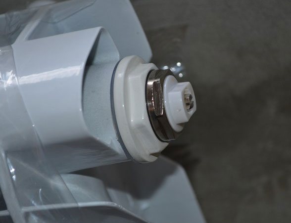
A radiator valve designed for manual balancing of heating consists of the following parts:
- Brass body with threaded pipe connections. Inside, by casting, a saddle is made - a vertical round channel, slightly expanding upward.
- Locking and regulating spindle with a working part in the form of a cone that enters the seat when screwing in and restricts the flow of water.
- O-rings made of EPDM rubber.
- Protective plastic or metal cap.
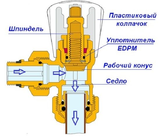
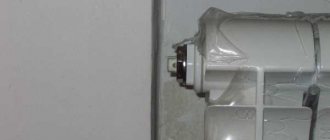
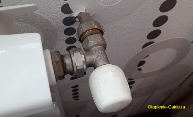
The figure shows a valve from Caleffi (website - https://www.caleffi.com)
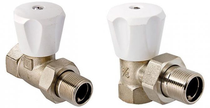
Note. All well-known manufacturers - Danfoss, Herz, Caleffi and others - offer 2 types of valves - straight and angle.The principle of operation is the same, only the form changes.
The balancing valve device is shown in more detail in the diagram above. It shows that the rotation of the spindle leads to an increase or decrease in the flow area, and the adjustment is performed. The number of revolutions from closed to maximum open position - from 3 to 5, depending on the manufacturer of the valve. To turn the stem, you need to use a regular or special hex key.
Trunk cranes differ from radiator cranes in dimensions, inclined spindle position and fittings designed for:
- draining the coolant;
- connection of measuring devices;
- connecting the capillary tube from the pressure regulator.
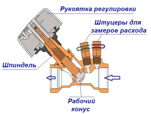
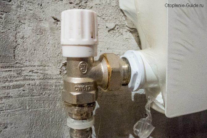
Main valve device for balancing heating branches
For reference. Radiator valve models, for example, from the Oventrop brand, are also equipped with a drain pipe.
The range of balance cranes is constantly expanding due to the emergence of new high-tech products. An example is an Italian-made Caleffi vertical valve equipped with a flow meter.
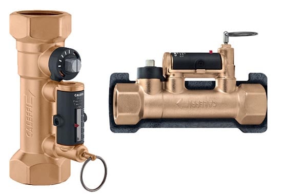
Caleffi valve with flow meter can be mounted in 2 positions - horizontal and vertical
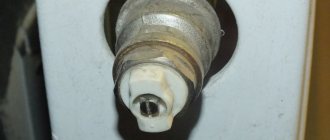
Air vent
Quite often, air locks form in CO. As a rule, there are several reasons for their appearance:
- boiling of the coolant;
- high air content in the coolant, which is automatically added directly from the water supply;
- As a result of air leaks through leaking connections.
The result of air locks is uneven heating of radiators and oxidation of the inner surfaces of the CO metal elements. The air relief valve from the heating system is designed to evacuate air from the system in automatic mode.
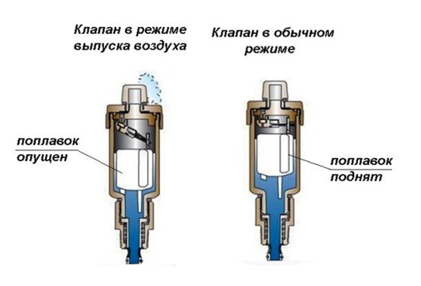
Structurally, the air vent is a hollow cylinder made of non-ferrous metal, in which a float is located, connected by a lever with a needle valve, which in the open position connects the air vent chamber to the atmosphere.
In working condition, the inner chamber of the device is filled with a coolant, the float is raised, and the needle valve is closed. If air enters, which rises to the upper point of the device, the coolant cannot rise in the chamber to the nominal level, and therefore, the float is lowered, the device operates in the exhaust mode. After the air is released, the coolant rises in the chamber of this kind of fittings to the nominal level, and the float takes its regular place.
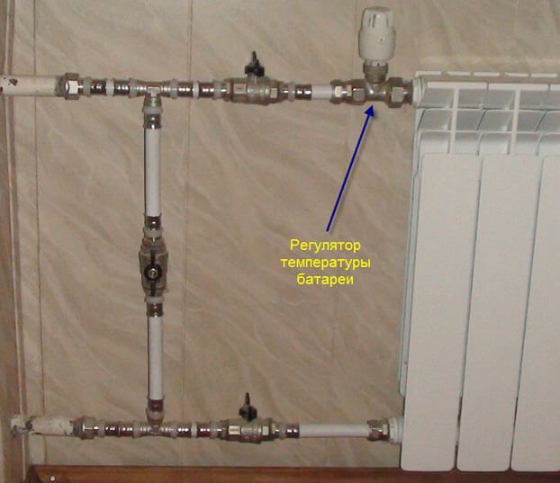
Valve installation location
There are points in the heating system where air is necessarily collected. So, Mayevsky's taps in the apartment should be installed on each radiator. In many modern radiator models, air bleed devices are installed at the manufacturing stage by the manufacturers themselves.
We recommend that you familiarize yourself with: How to build a garage from a profile pipe?
Note! If you have classic radiators, then the air valve should be installed in the upper part of it, which is located opposite the connection.
So you yourself can always control the normal operation of your heating batteries and not depend on the desire of the housing office employees or the mood of the neighbors from above.
Points for installing air relief valves:
- radiators, bathroom coil, upper part;
- the top point of the pipeline;
- heating boiler safety system in individual communications;
- for hydraulic branching;
- on the collectors of the common manifold;
- on any U-shaped loops in communications, at the top point;
- for expansion joints in plastic heating systems.
It should be understood that air always accumulates in the upper part of the communications.An air lock can arise in the bend of a plastic pipe if the installation was carried out incorrectly and there was a temperature deformation.
The easiest way to get rid of the plug in the pipeline permanently is to cut a tee into the pipe. A valve is installed on the free vertical branch of the tee (the diameter of which is selected accordingly) to release air.
Back
In gravity CO, there are conditions under which the coolant can change the direction of movement. This threatens to damage the heat exchanger of the heat generator due to overheating. The same can happen in sufficiently complex COs with forced movement of the coolant, when water, through the bypass pipe of the pumping unit, enters the boiler back into the boiler. Mechanism of action check valve in the heating system quite simple: it passes the coolant only in one direction, blocking it when moving back.
There are several types of this kind of fittings, which are classified according to the design of the locking device:
- disc-shaped;
- ball;
- petal;
- bivalve.
As it is already clear from the name, in the first type, a steel spring-loaded disk (plate), connected to the stem, acts as a locking device. In a ball valve, a plastic ball acts as a shutter. Moving "in the right" direction, the coolant pushes the ball through the channel in the body or under the cover of the device. As soon as the circulation of water stops or the direction of its movement changes, the ball, under the influence of gravity, takes its original position and blocks the movement of the coolant.
In the petal, the locking device is a spring-loaded cover, which is lowered when the direction of water in CO changes under the action of natural gravity. The bivalve element is installed (as a rule) on large diameter pipes. The principle of their work does not differ from the petal one. Structurally, in such an armature, instead of one petal, spring-loaded from above, two spring-loaded flaps are installed.
These devices are designed to regulate temperature, pressure, and stabilize the work of CO.
Balancing
Any CO requires hydraulic adjustment, in other words - balancing. It is carried out in various ways: by correctly selected pipe diameters, washers, with different flow cross-sections, etc. balancing valve for heating system.
The purpose of this device is that the required volume of coolant and the amount of heat can be supplied to each branch, circuit and radiator.
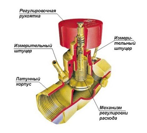
The valve is a conventional valve, but with two fittings installed in its brass body, which make it possible to connect measuring equipment (manometers) or a capillary tube with an automatic pressure regulator.
The principle of operation of the balancing valve for the heating system is as follows: By turning the adjusting knob, it is necessary to achieve a strictly defined flow rate of the coolant. This is done by measuring the pressure at each nozzle, after which, according to the diagram (usually supplied by the manufacturer to the device), the number of turns of the adjusting knob is determined to achieve the desired water flow rate for each CO circuit. Manual balancing regulators are installed on circuits with up to 5 radiators. On branches with a large number of heating devices - automatic.
What is the difference between a balancing valve and a conventional tap
In contrast to conventional shut-off and control valves, the balancing valve, due to the combined action of the diaphragm and the spring, reacts to pressure changes occurring in the installation.It maintains the differential pressure in the dead ends of the circuit in accordance with the set value. This regulation is ideal for heating appliances that constantly operate at a balanced heating fluid flow.
This level of control of hydrodynamic modes increases the efficiency of the heating network, and reduces the cost of heating services and cannot be provided in the conditions of using only conventional ball valves.
The difference between the balancing valve and typical valves:
- Reduces the cost of pumping equipment for the circulation of the coolant.
- Supports temperature difference - delta T. Pressure independent valves that provide the design flow through the radiator for full or partial load situations. Therefore, the calculated delta T value will be reached, which will lead to an increase in the efficiency of the heat sources or heat exchangers.
- It balances the circulating flow, measures the differential pressure in the operating state and blocks the disturbance of the set hydraulic regime through the radiator.
- Adjusting the heating water consumption, depending on the purpose of the objects, brings a significant economic effect due to the low specific fuel consumption.
- Setting the minimum gas consumption and maintaining a constant temperature regime in all rooms, including during the period of temporary absence of residents.
Bypass
This is another CO element designed to equalize the pressure in the system. Principle of operation bypass valve of the heating system is similar to the safety one, but there is one difference: if the safety element bleeds off excess coolant from the system, then the bypass returns it to the return line past the heating circuit.
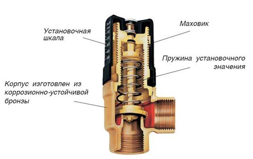
The design of this device is also identical to the safety elements: a spring with adjustable elasticity, a shut-off diaphragm with a stem in a bronze body. The flywheel adjusts the pressure at which this device is triggered, the membrane opens the passage for the coolant. When the pressure in CO stabilizes, the membrane returns to its original place.
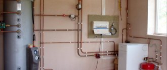
Where is it supposed to put the valve
The installation location depends on the piping layout. It is important to remember that the relevance of the installation of these devices is determined at the design stage. If it is possible to do without them, it is better to use standard means of regulation - taps, thermostats. Any additional shut-off valves affect the hydraulic resistance, which reduces the speed of hot water movement.
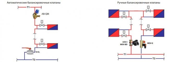
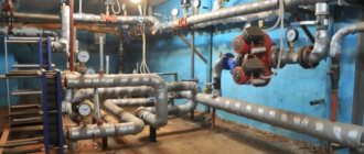
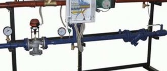
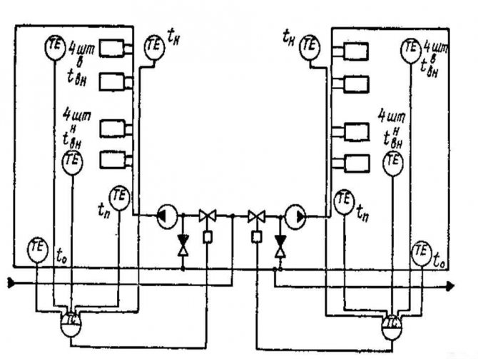
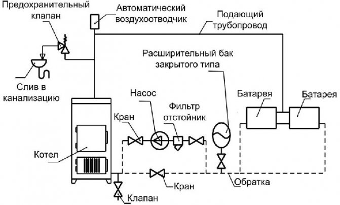
Example installation diagrams for one-pipe and two-pipe systems
Installation locations of balancing valves, depending on the heating scheme:
- One-pipe. Installed in front of radiators, it only regulates the volume of the coolant for a separate heat supply branch.
- Two-pipe. There are two possible installation options. The first is the installation of the manual model on the supply pipe. The second is a combination of an automatic balancing valve on the return line with a differential pressure regulator in the supply. This balances the hydraulic balance.
Important: the balancers are not installed in a radial or collector heating circuit. Accurate adjustment of work is impossible due to constant pressure changes in different sections of the line.
Three-way
There is a practice to achieve a certain temperature of the coolant in various branches and circuits of the CO by mixing or dividing the coolant flows. Three-way valve on the heating system plays the role of a device that regulates the temperature of the working fluid after the heat generator.
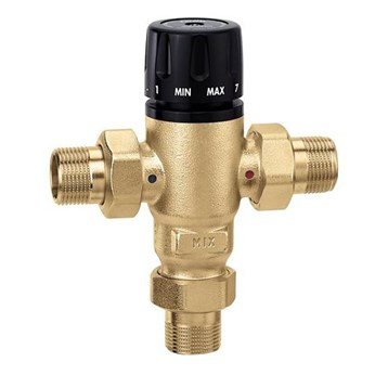
The design of the mixing valve is simple: there are three holes in the body of the device, two inlets and one outlet. Isolating devices have one input and two outputs.
The main control device of this element is a thermal head, inside which there is a reservoir with a liquid (bellows). When the remote sensor is heated, the liquid in it expands and enters the bellows. The volume of this reservoir expands and acts on the valve stem, which opens or closes the mixing or splitting ports. The separating types of this CO element use the same principle, but the stem does not open the passage for flows, but divides one flow into two.
The device can be controlled not only by the thermostatic head. Manual devices are quite popular. The depth of pushing the rod is determined by the rotation of the control handle. Today, on the market of climatic technology, these devices with electric and servo drives are widely represented.
Methods for adjusting the heating system
It often happens that mistakes made during the installation of the heating system can only be detected after the equipment is put into operation. Among the reasons for the occurrence of failures in the heat supply of the house is the incorrect determination of the required amount of coolant. When there is little liquid in the system, it will be cold in the room, and if there is a lot, the air overheats and does not pass into other rooms.
Adjustment of the heating structure is required to adjust the operation. If it is not produced, then the service life of the equipment will be significantly reduced.
The heating system is regulated by one of two methods:
- in a qualitative way - by changing the temperature of the coolant;
- quantitatively - with it, the volume of the liquid is changed.
Qualitative regulation is carried out at the heat source, and quantitative regulation is carried out directly on the heating structure. Before proceeding with its implementation, determine the volume of the consumed liquid and the temperature of the coolant, using special devices for this - a water meter and a flow meter.
When there are no such devices, then the actual flow rates are compared with the calculated data. Most often, two-pipe heating systems are installed that can provide warmth and comfort in the house. You will also need shut-off and control valves for heating.
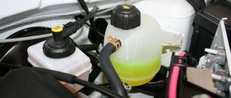
Automatic make-up device
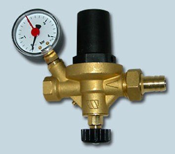
Due to various circumstances (natural evaporation, operation of the safety element, etc.), the volume of the coolant in CO may decrease. The less coolant, the more air in the system, which inevitably disrupts the circulation of water in CO and overheating of boiler equipment. To prevent air from entering the system, it is necessary to replenish the amount of coolant in time. You can do this manually, or you can install heating system make-up valve, thereby to organize automatic replenishment of CO with a coolant.
The design of this kind of fittings practically does not differ from safety fittings, but the principle of operation is exactly the opposite: as long as there is the necessary pressure in the CO, which supports the diaphragm against the seat, the spring is in a compressed state. When the pressure drops below the minimum, the spring straightens and moves the membrane away from the seat, allowing water from the supply tank or water supply network to enter the CO. In fig. The construction of this device is shown below.
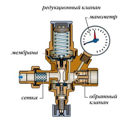
As CO is filled, the pressure in it increases, the spring is compressed, and the membrane sits in the seat on the body, shutting off the make-up.
Important! Valve selection is a complex and important process that is best left to professionals.